 Scott Swaaley
I thought it would be interesting to show the evolution of our schematics over time, focusing on our primary power center - our 5kW DC Braking power supply - the switching of power sources - and control. We detailed the unusual specs for our power supply in a previous project log and describe the overall function of our device in the project details but figured we'd show the quick evolution here. You'll probably notice that there are no microcontrollers in these - that's because an adviser told me that getting firmware NRTL Listed in a safety product was a huge pain in the butt and best avoided for a first product. Also, keep in mind that the goal here was to make a plug-and-play device that works irrespective of what is happening downstream. Lastly, this is all single-phase because our switch to poly-phase is a recent change.
 |
The beginning. It didn't take long for me to start looking at thyristors for rectification so here is one of the first schematics with only relay logic and simple R/C/D thyristor control. What we learned: - MOVs do not effectively reduce arcing. This causes severe arcing when the DC relay opens. - Half-wave rectified DC does not brake the motor. |
 | Key Control. Multiple people were asking about the ability to restrict access to equipment so we started experimenting with simple ways to integrate a key switch into the device. What we learned: - Electrically, this is easy. - It's really hard to find a key switch that can switch even a small AC coil without getting fried from arcing. |
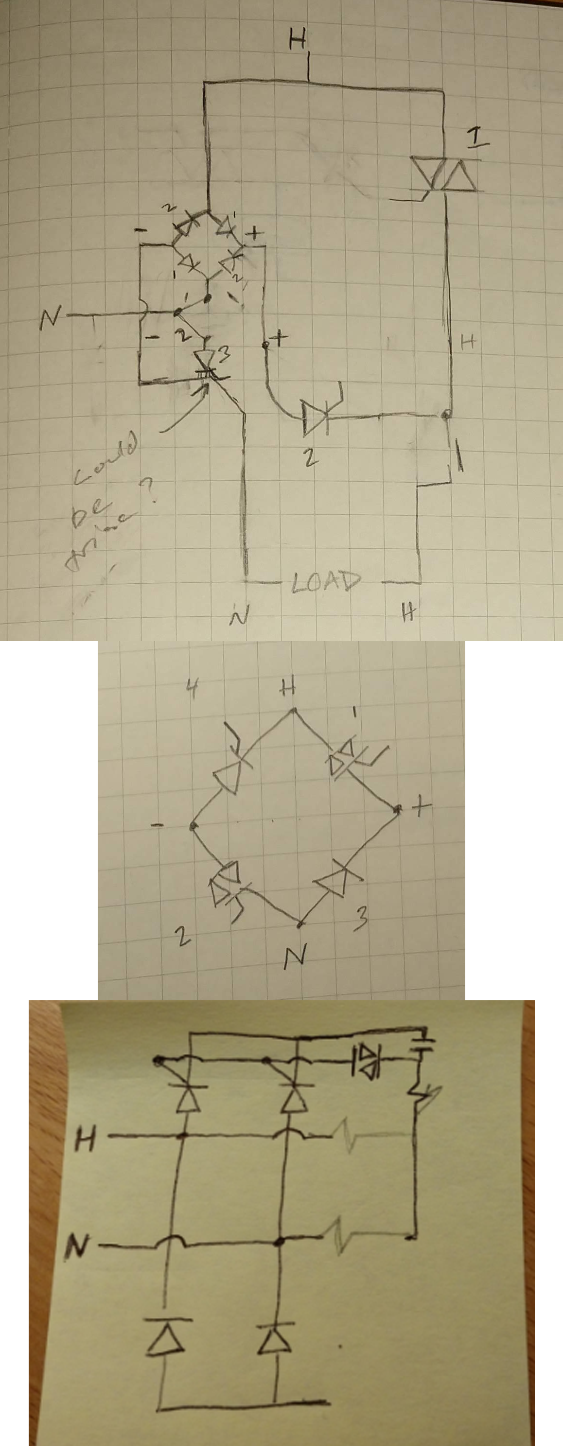 | Full Wave. It was now obvious that we needed full wave rectification but with relays as the most expensive element by far, we were trying to do it all while minimizing the contacts required. We experimented with full-wave-rectifiers in front of and behind an SCR, full converters, and semi-converter rectification topologies. What we learned: - Trying to control two thyristors with independent reference voltages is crazy complicated and would bump up control complexity significantly. - It's VERY easy when designing these topologies and switching between AC run mode and DC braking to create an accidental short across mains through one of the diodes or thyristors in the rectifier. - The reality of relay make and break times can also create make-before-brake situations that also short mains. - Shorting mains makes big booms. - Isolation of the o-scope is critical. |
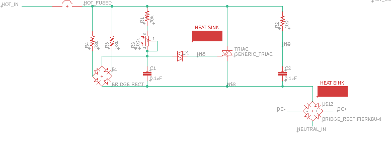 | Triac Turns out that the most cost efficient way for us to provide the switching and connectivity we wanted was with a triac before a standard full-wave rectifier and to control it with a simple R/C/Diac circuit. You can adjust the pot to adjust firing angle and thus output voltage. What we learned: - Output voltage control (via R/C/D pot) is really funky and has to be turned up before being reduced to the setting you want. Like an old lantern. A lucky find in an online forum pointed out an elegant solution to this (see FWR and resistors to left of power schematic). - Arcing can be slightly helped (but not totally eliminated) with an RC snubber. - RC snubbers create consistent leakage current and also inrush during switching, which can cause problems. |
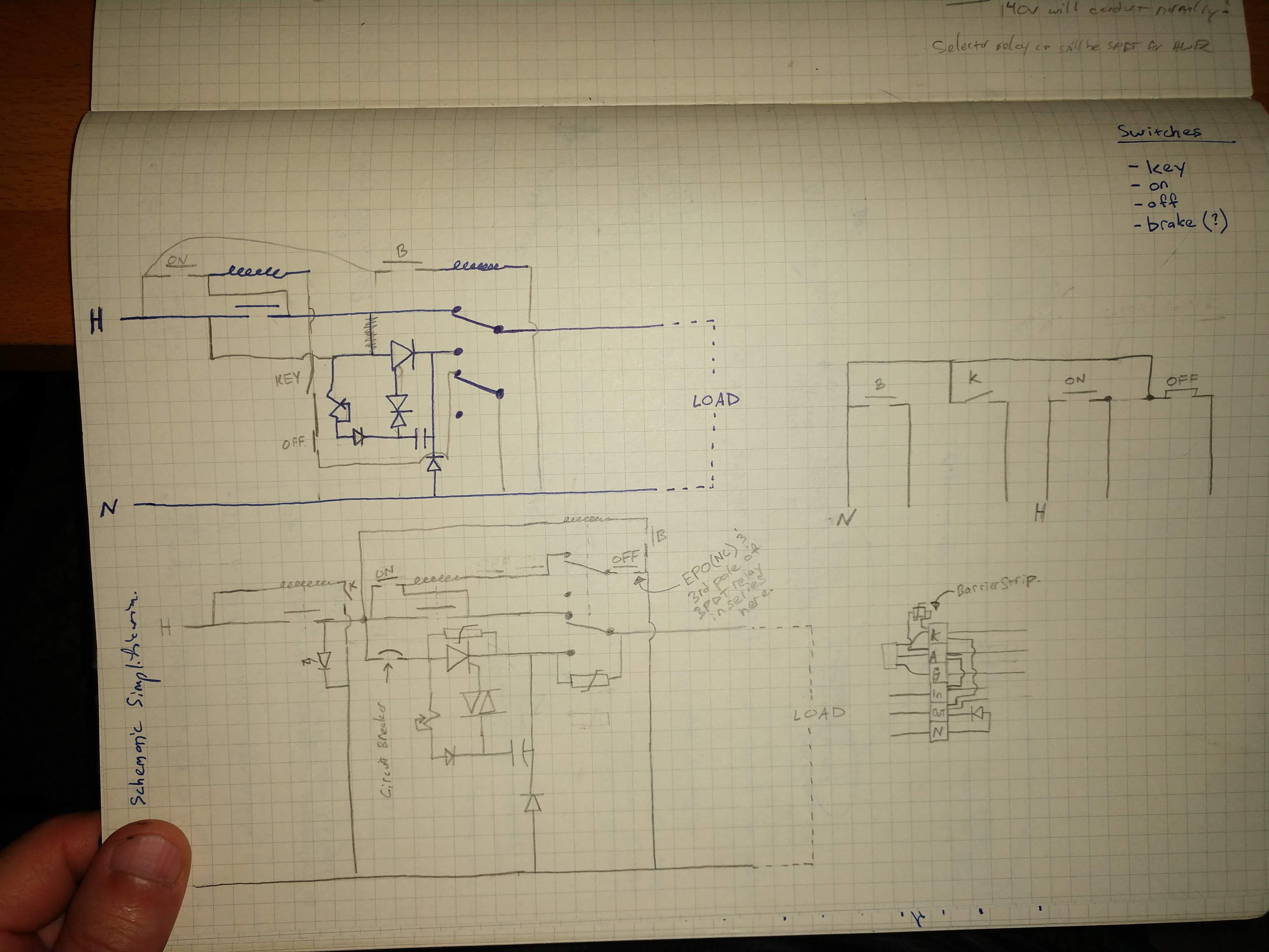
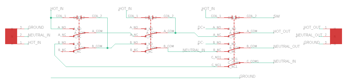 | Switching Detection and Control The circuit has to detect the status of the switch on the tool that's plugged in (the restart prevention and post-braking mode), switch between AC and DC modes when activated, and not short out or cause fires. After LOTS of relay puzzles, we arrived at this: What we learned: - We could feed a sensing current through the power tool (load) to sense the position of the tool switch. This worked with a broad range of motor impedances. - We could use spare contacts in relays (negligible cost adder) to get latching functionality. - This setup works! |
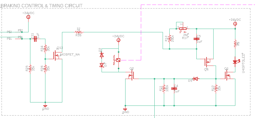  | Moving to Digital(ish) Control After showing this product off a bit to friends and a few potential clients, they didn't like needing to hold down the brake button and thought it would be too easy to do it wrong and still get hurt. So we made a BIG jump to digital control and timing. Here is the first attempt at a discrete implementation. What we learned: - Working with discrete parts, passives tolerances, and variant voltage thresholds SUCKS. Not practical or reliable at all. Lots of oops-BOOM moments. |
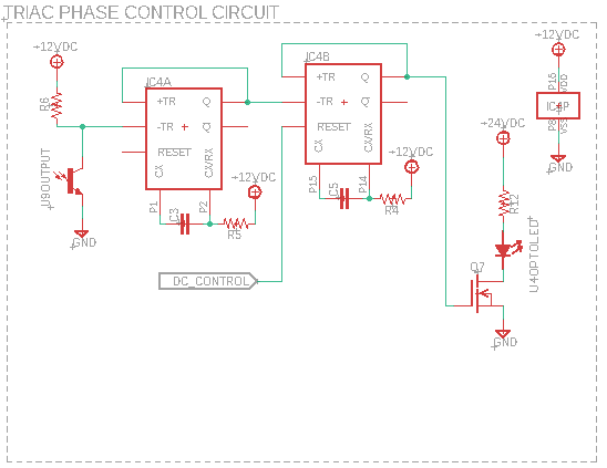 | A Bit More Digital Finally, we took the plunge and built a galvanically isolated control circuit for the triac firing (no more R/C/D madness) and process timing. Not elegant ... but getting closer. What we learned: - With multi-second timing, it's really hard to find low-tolerance SMD capacitors in the tens of uF. |
That's where we're at so far. Lots of progress and learning. Hope you enjoyed that little adventure.
License for schematics above: CC BY-NC-ND 4.0
Discussions
Become a Hackaday.io Member
Create an account to leave a comment. Already have an account? Log In.