0%
0%
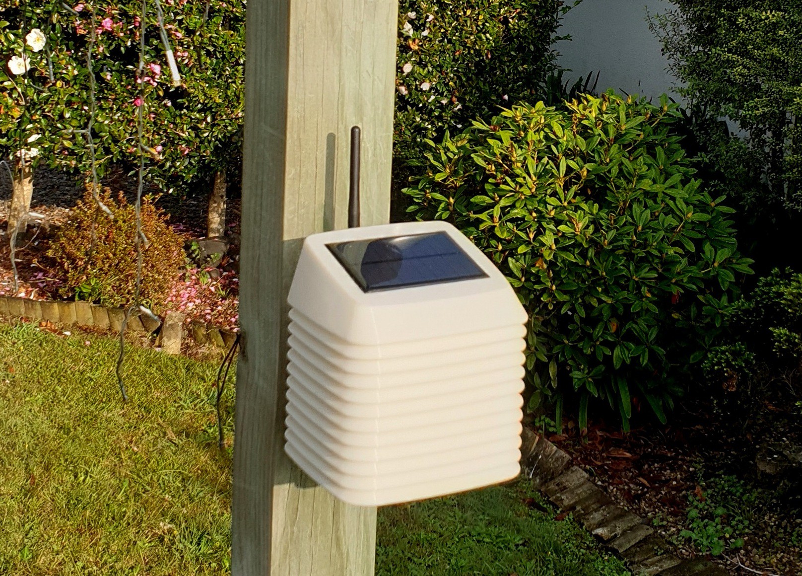
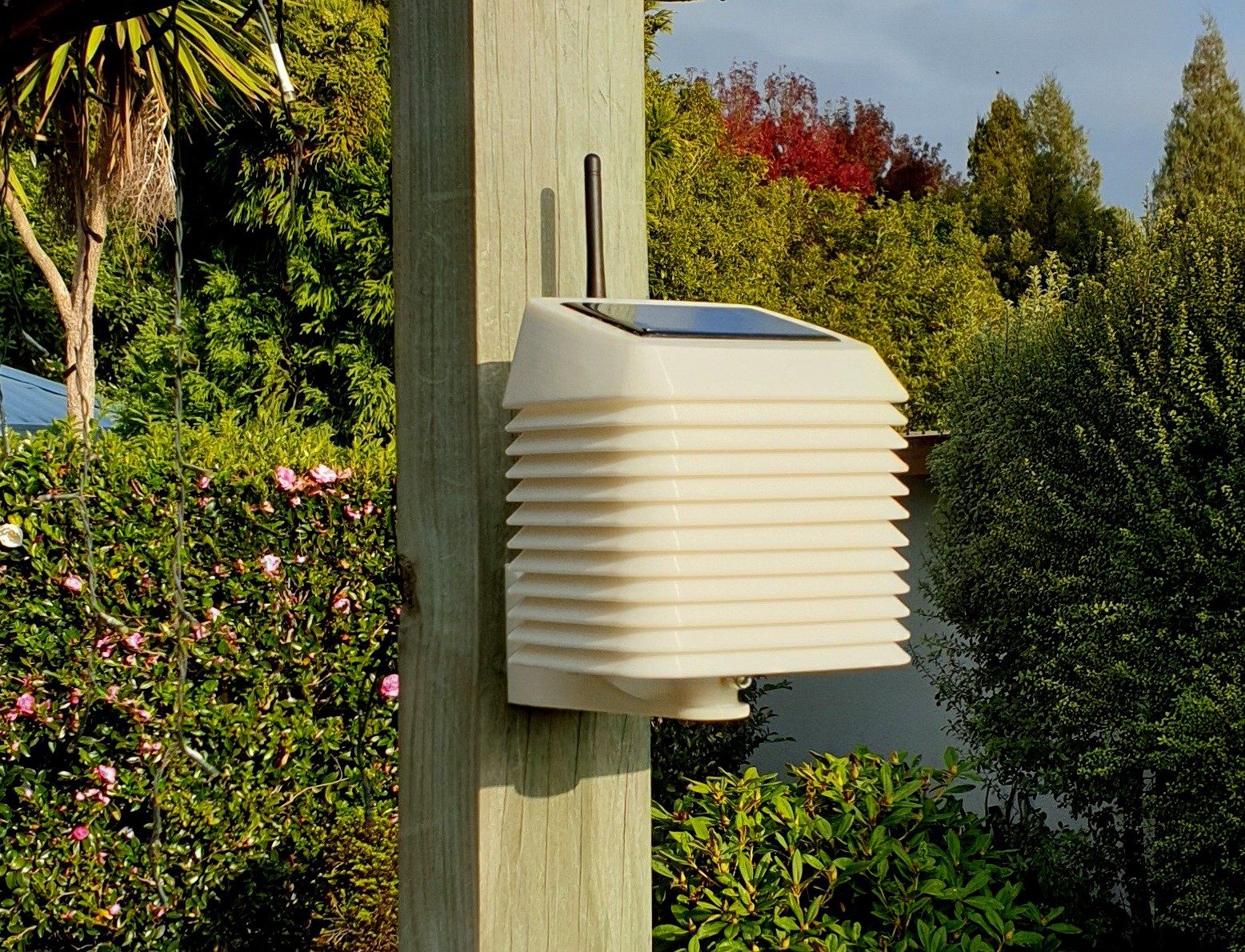
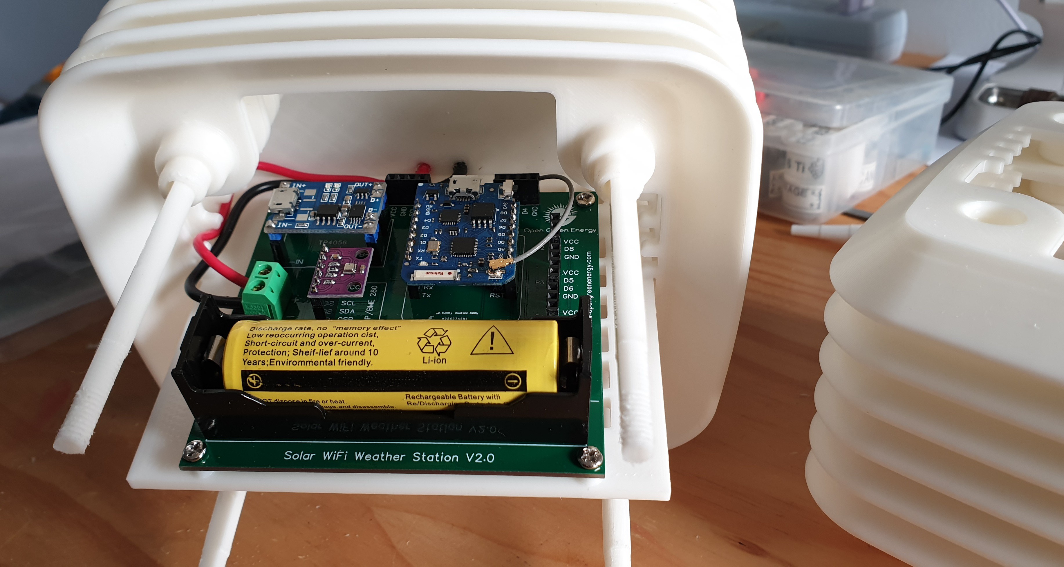
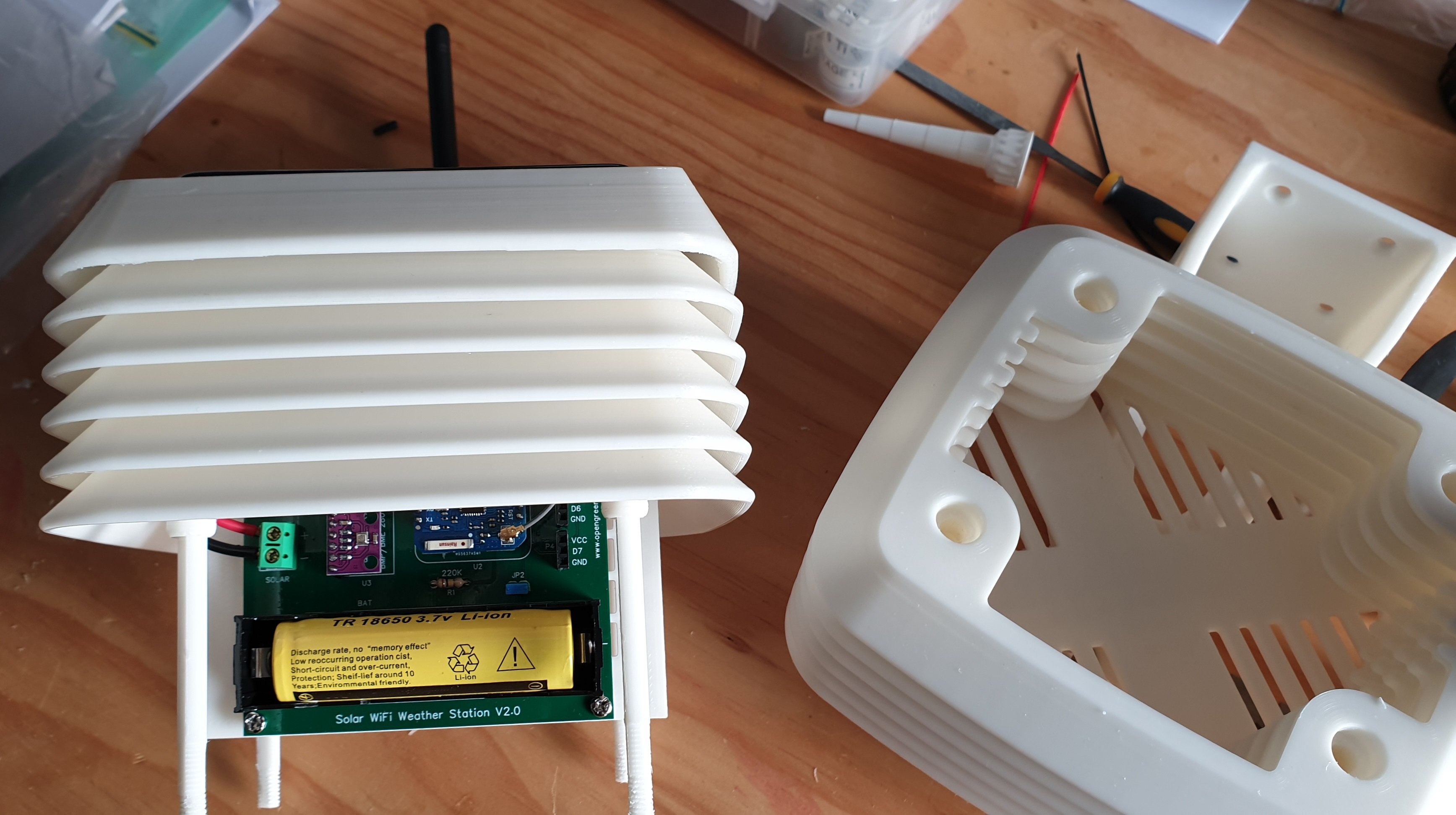
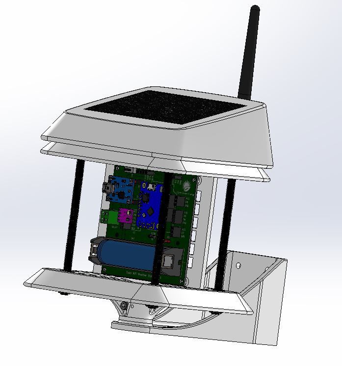
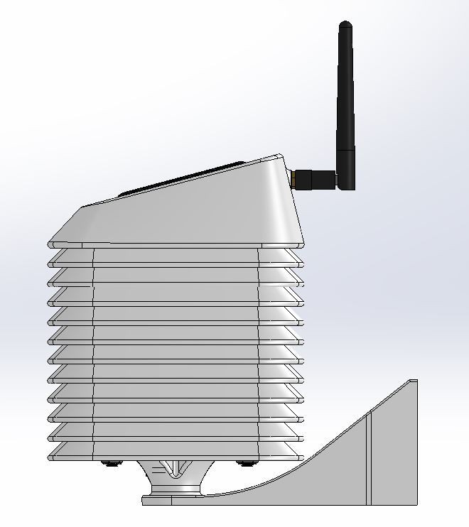
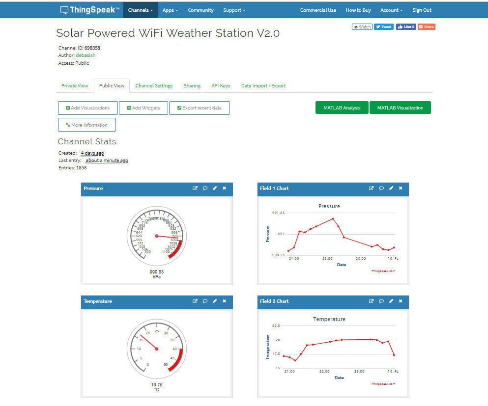
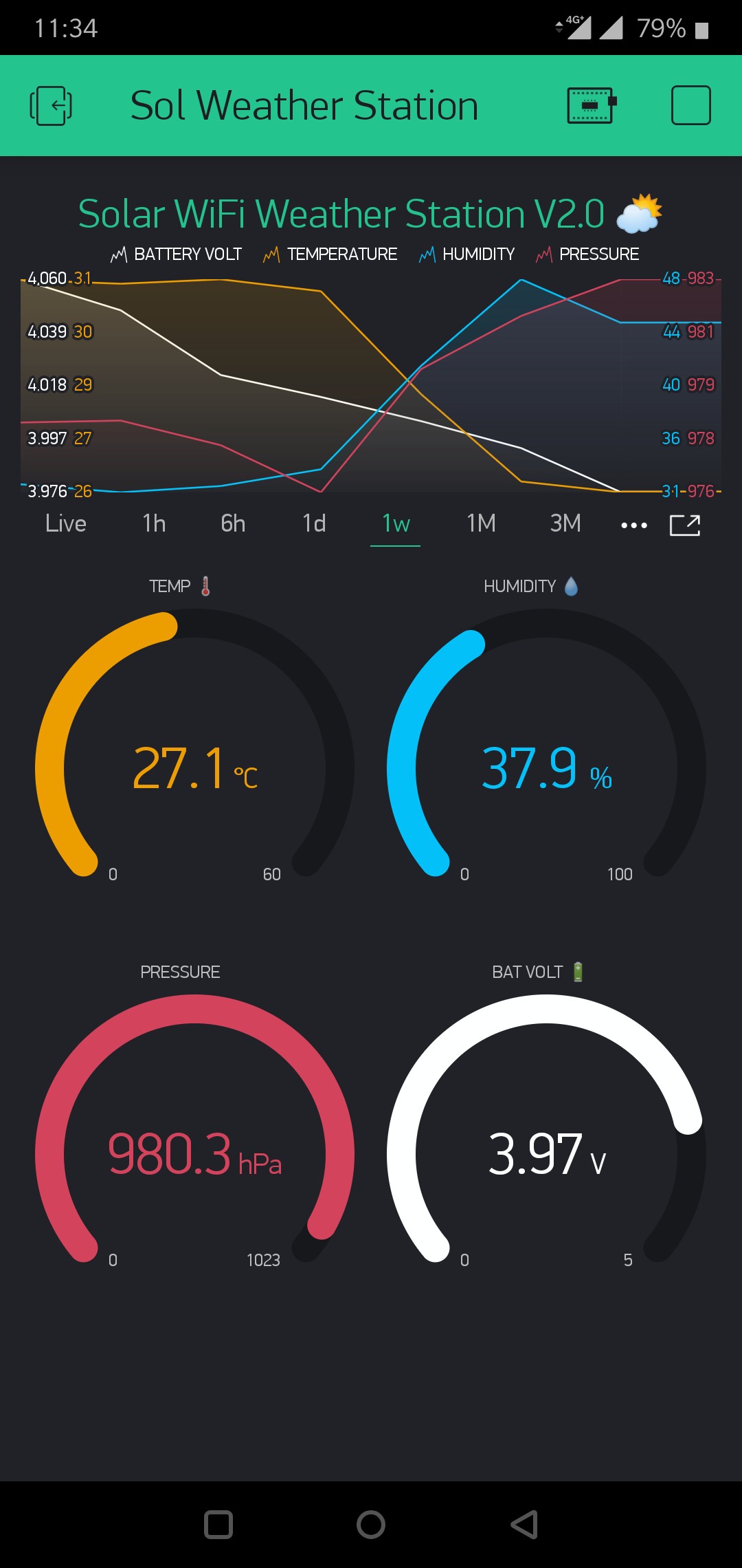
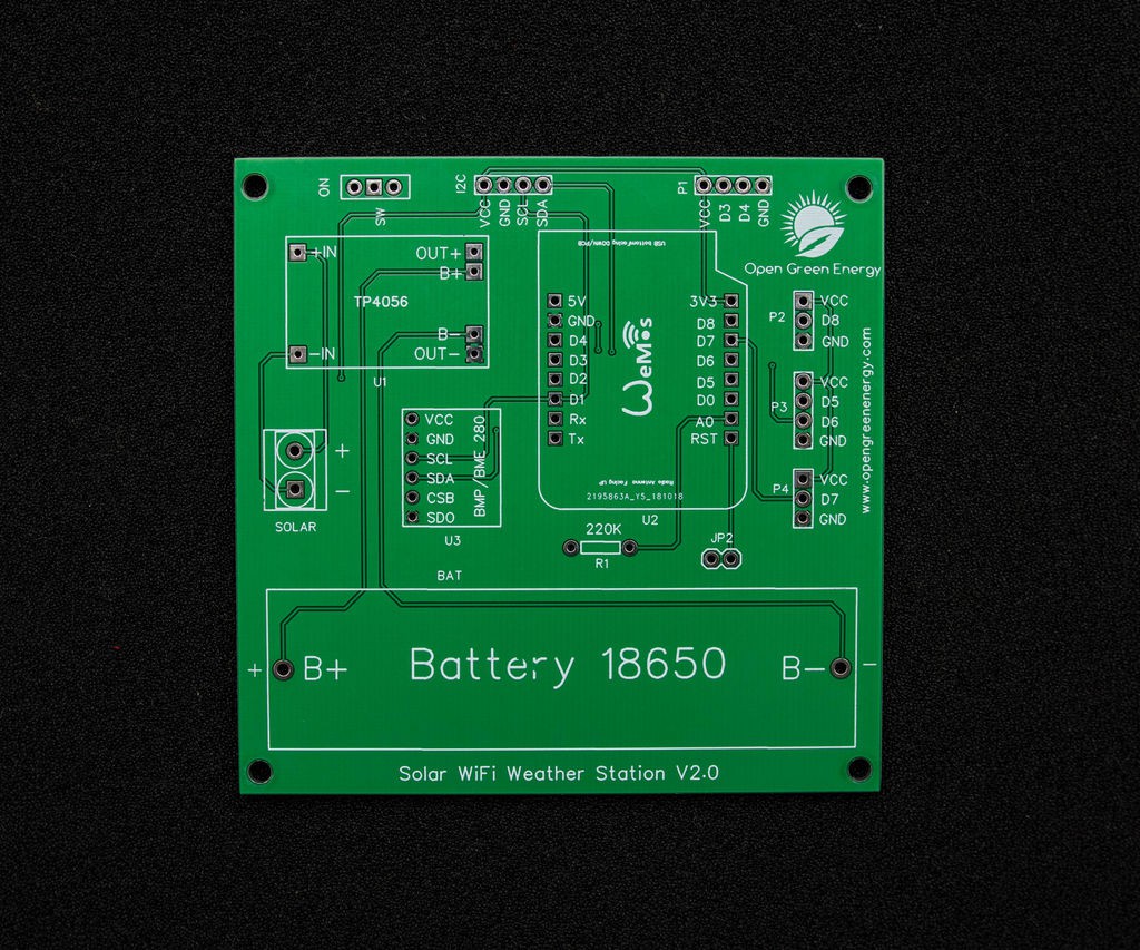
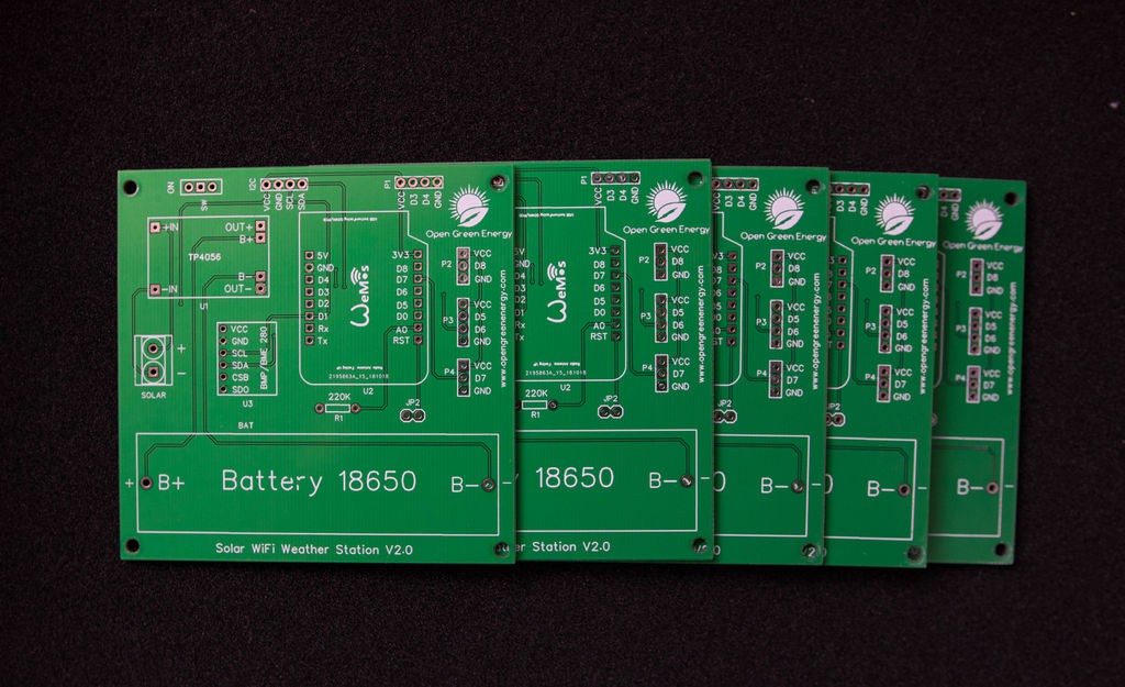
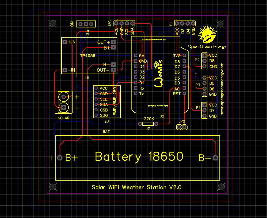
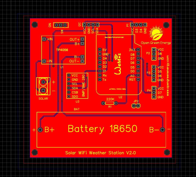
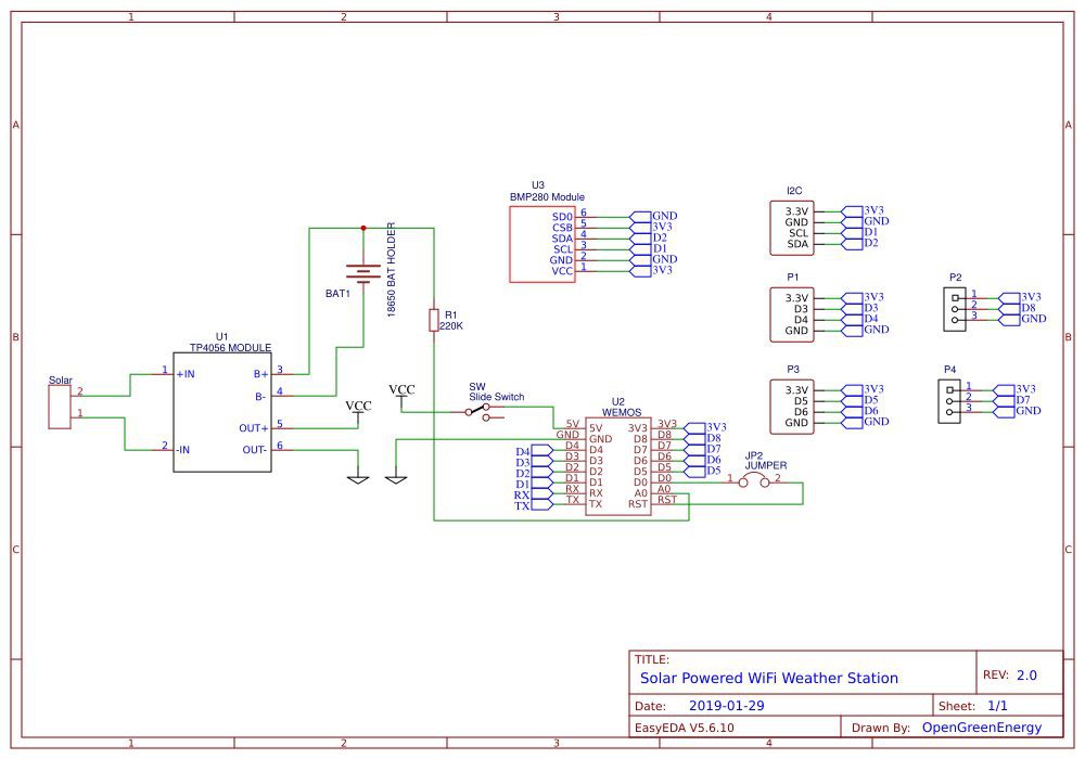
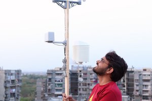
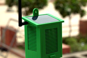
Solar Powered WiFi Weather Station V2.0
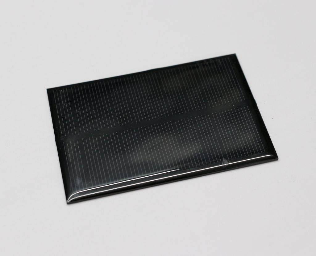
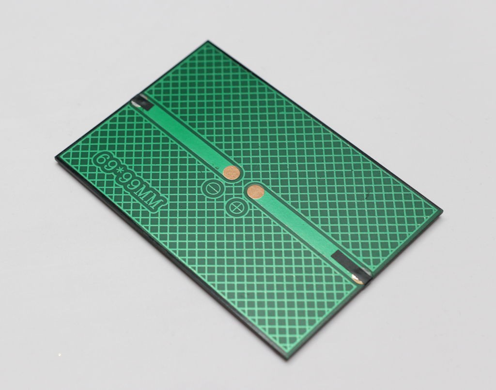
A solar-powered ESP8266 based Weather Station, which can run years without taking power from an external source
 Open Green Energy
Become a Hackaday.io member
Already have an account? Log in.
Just one more thing
To make the experience fit your profile, pick a username and tell us what interests you.
Pick an awesome username
hackaday.io/
Your profile's URL: hackaday.io/username. Max 25 alphanumeric characters.
Pick a few interests
Projects that share your interests
People that share your interests


 Jon
Jon
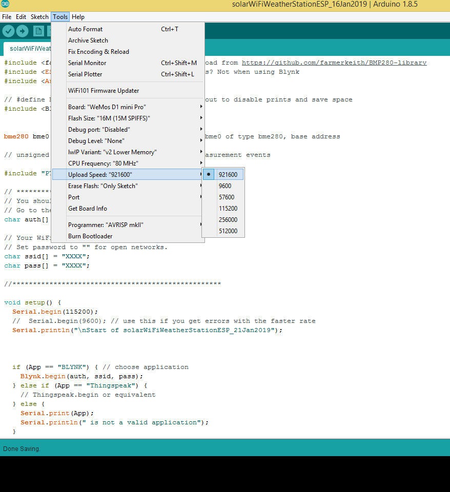
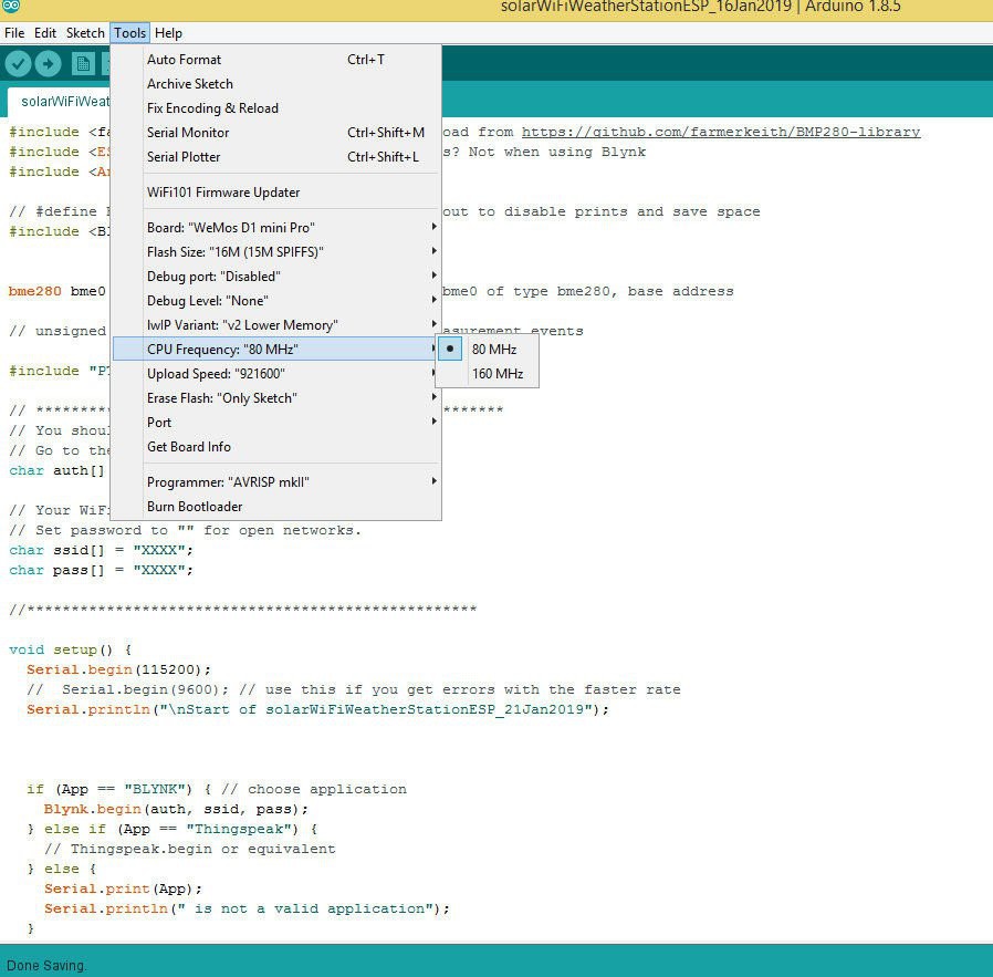
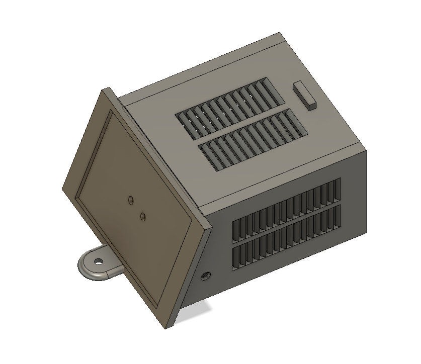
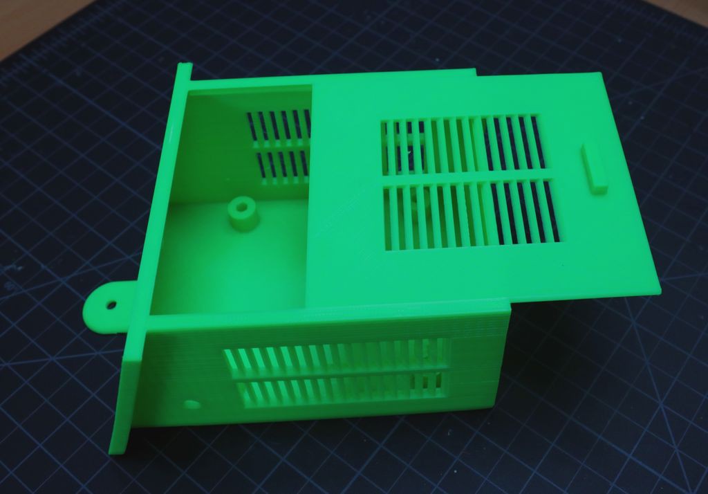
Good project and description, but seems the STL files are from the other one, not this v2?