 Jon
JonOverview
The Smart Plant was designed to be flashed with the ESPHome firmware, however it can be directly programmed through Arduino or ESP-IDF. And since the code is yours, so it's the data you gather, stream it to your Home Assistant server and automate your irrigation on the plant's demand!
Want to get one?

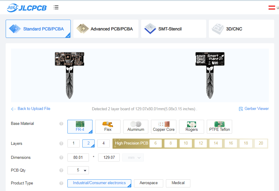
In any case, all the design files are available on my Github, and I have prepared an extended documentation page for any user willing to know more about the project
Specifications:
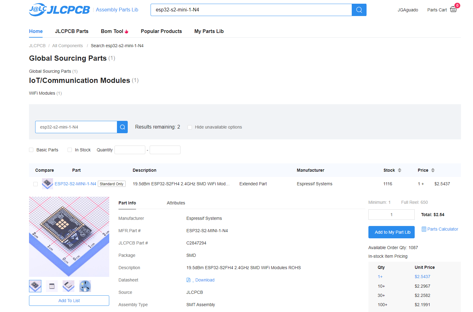
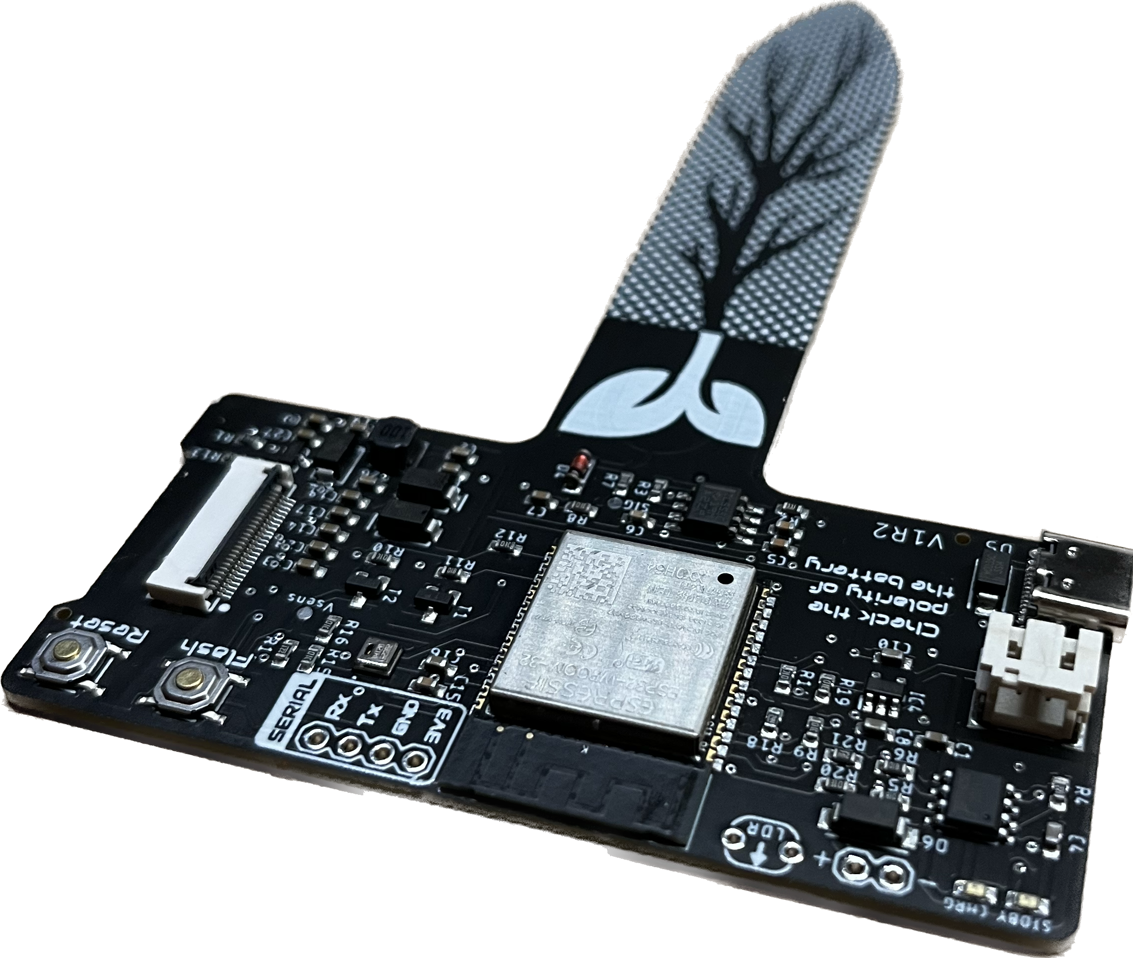
- Microcontroller: ESP32-S2-MINI-1-N4R2 with 4 MB in-package flash and 2MB PSRAM
- Firmware compatible:
- ESPHome, highly recommendable for its native integration into Home Assistant
- Arduino
- ESP-IDF
- Sensors:
- Soil moisture: Capacitive probe built-in
- Light: VEML7700-TR digital sensor
- Air Temperature & Humidity: AHT20 digital sensor
- Battery level: MAX17048 digital sensor
- Power:
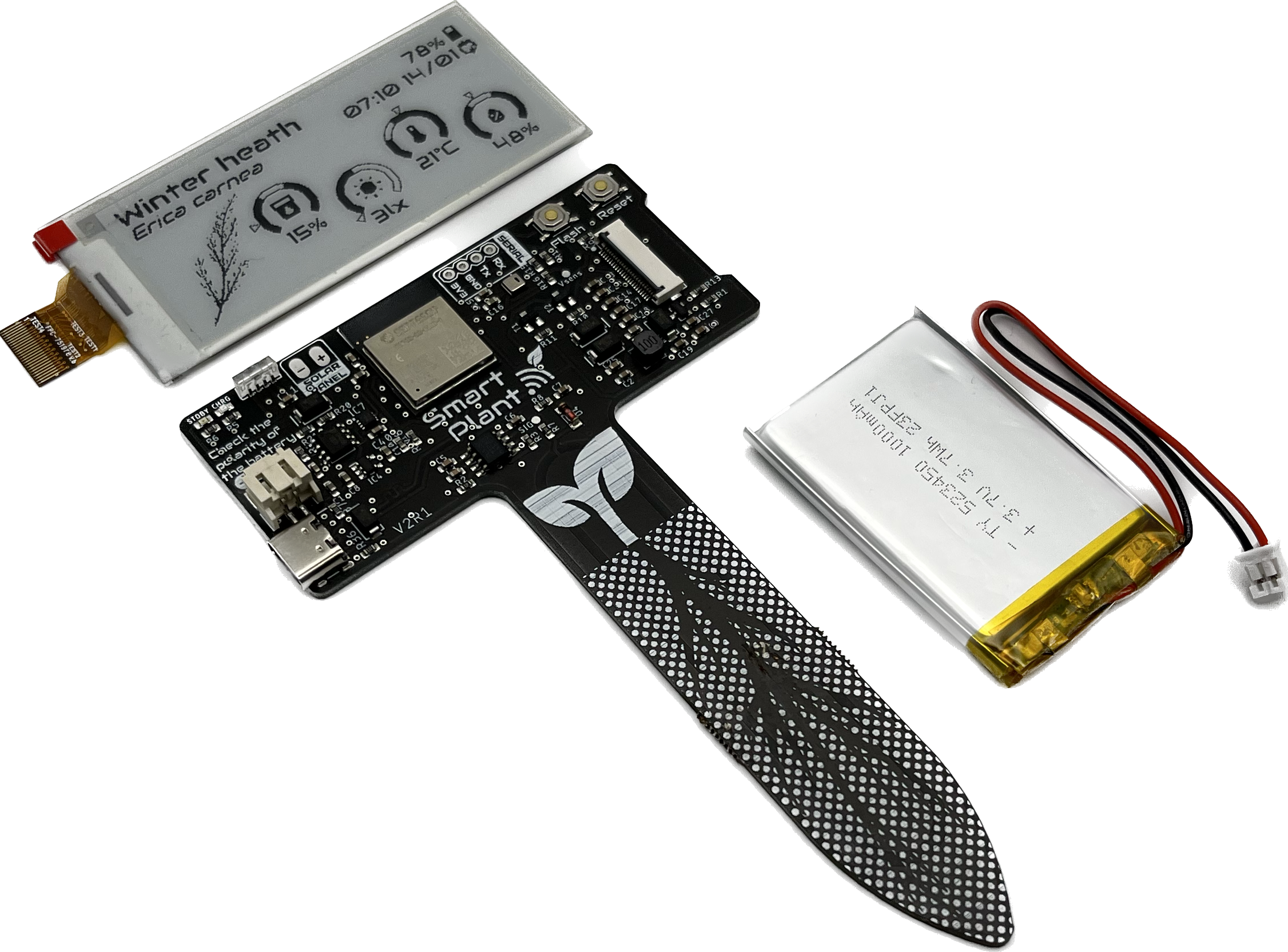
- 3.7V 1000mAh LiPo battery
- Charging through USB-C or solar panel (5V @500mA)
- Deep-sleep mode consumption: 450-500μA
- Standard mode consumption (10s awake, 1h deep-sleep): ~1mA
- Interface:
- USB-C for charging and programming
- UART port
- 2.4GHz Wifi
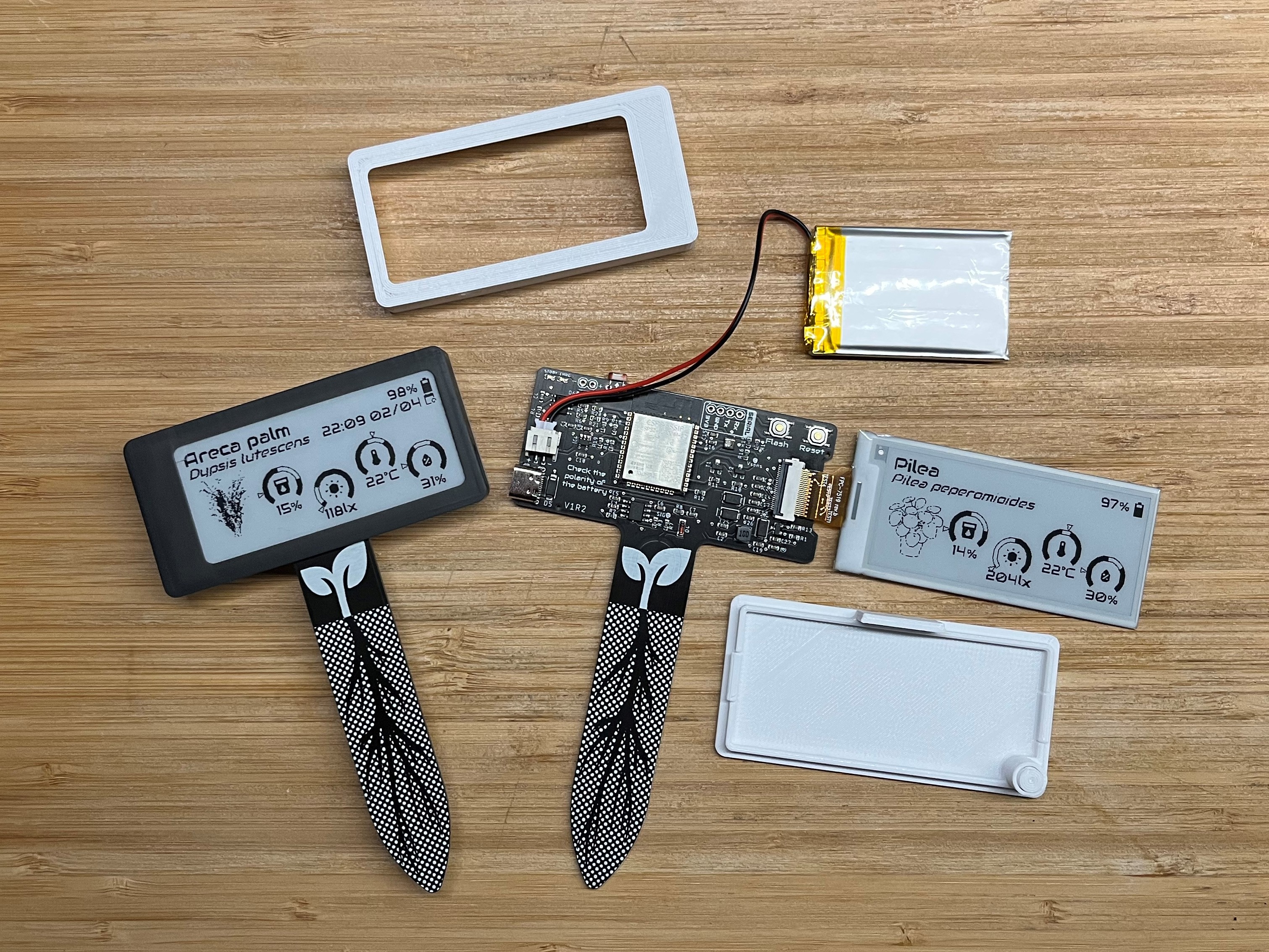
- Display: 2.9" black & white e-ink from Waveshare
Version log:
- Version 0: Very early prototypes to serve as proof of concept.
- V0R1: Protoboard with headers to be used as a shield for the TTGO T5 e-ink module
- V0R2: PCB designed to host the same module but with some additional THT components integrated
- Version 1: First designs on black PCBs with a more aesthetically oriented design.
- V1R1: Integrated the ESP32-S module and a photodiode as a light sensor
- V1R2: Corrected previous power module and replaced photodiode with LDR
- Version 2:
- V2R1: Replaced ESP32-S with ESP32-S2, added battery level sensor and digital light sensor.
The story behind
I started this project because I was missing some features on the popular Xiaomi Mi Flora. Those devices, despite being very useful, lack a key point: readability. Every time I wanted to check my plant's health I had to go to their app... With time I learned how to implement them into Home Assistant, receiving the data via Bluetooth on my RPi 4 and plotting the graphs I needed on my custom dashboards...
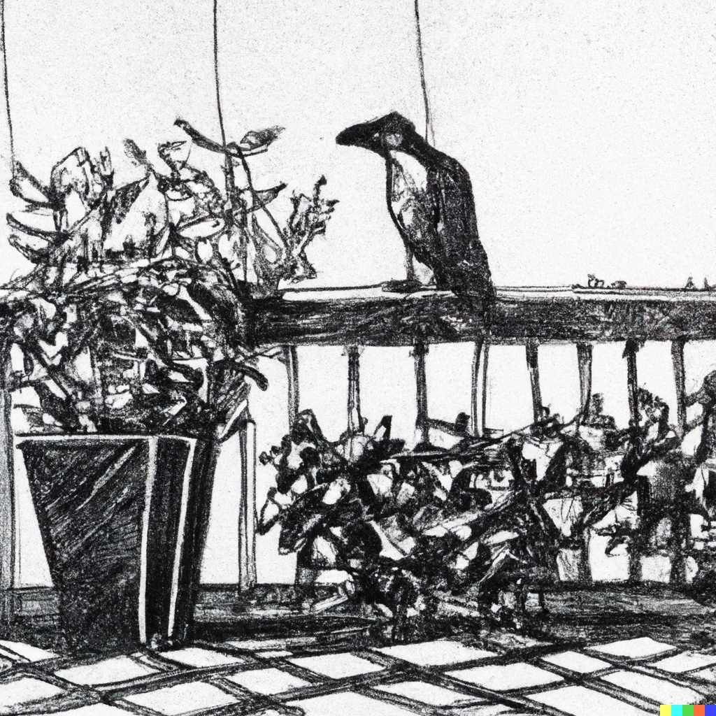
One day, I realized one of my Xiaomi's sensors was missing on the balcony pots. After an inquisitive search party, I found out that one of the black ravens from my neighborhood just decided to add this gadget to his collection of stolen items...
With a pot missing a key instrument for the plant's survival, I decided to come up with an alternative gadget that, not only would keep the features of streaming the data into my Home Assistant setup, but also provide more of a user-oriented readability features.
Daily usage: automations
I chose ESPHome as the main firmware for the Smart Plant, not only because of the direct support for the e-paper panel and the rest of the sensors on board but also because the integration into Home Assistant (HA) is immediate.
Through HA you can flash ESPHome directly on the Smart Plant and start logging the parameters from the first minute. Additionally, you can prepare beautiful dashboards to display the data and set some automations.
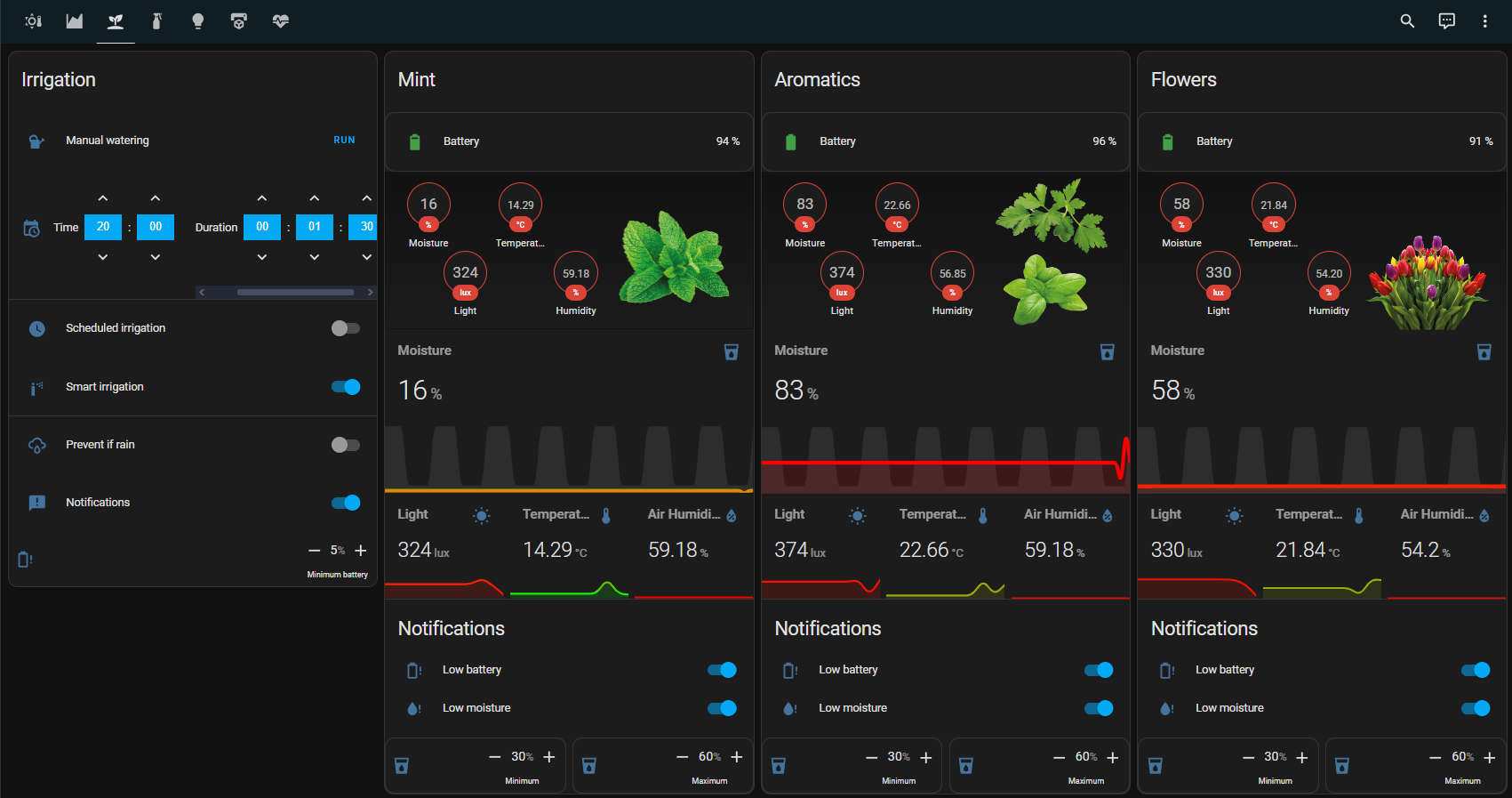
In summer, I have the Smart Plants on my balcony plants (4 different pots). Each of my pots have an individual irrigation pipeline that I control through my other project Smart Garden and the assistance of some automations programmed in HA. The automations do basically:
- At a certain time of the day (20:00), the system checks the moisture...


 Nathann
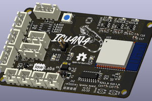
 iow Labs
 Open Green Energy
 Ulrich
I'm new with hackaday. Is there a way to order this device?
upd. Ach, found it, it was in the More → Tindle Marketplace menu: https://www.tindie.com/products/jgaguado/smart-plant/
Is the new batch expected?