 Andy
AndyQuick Links
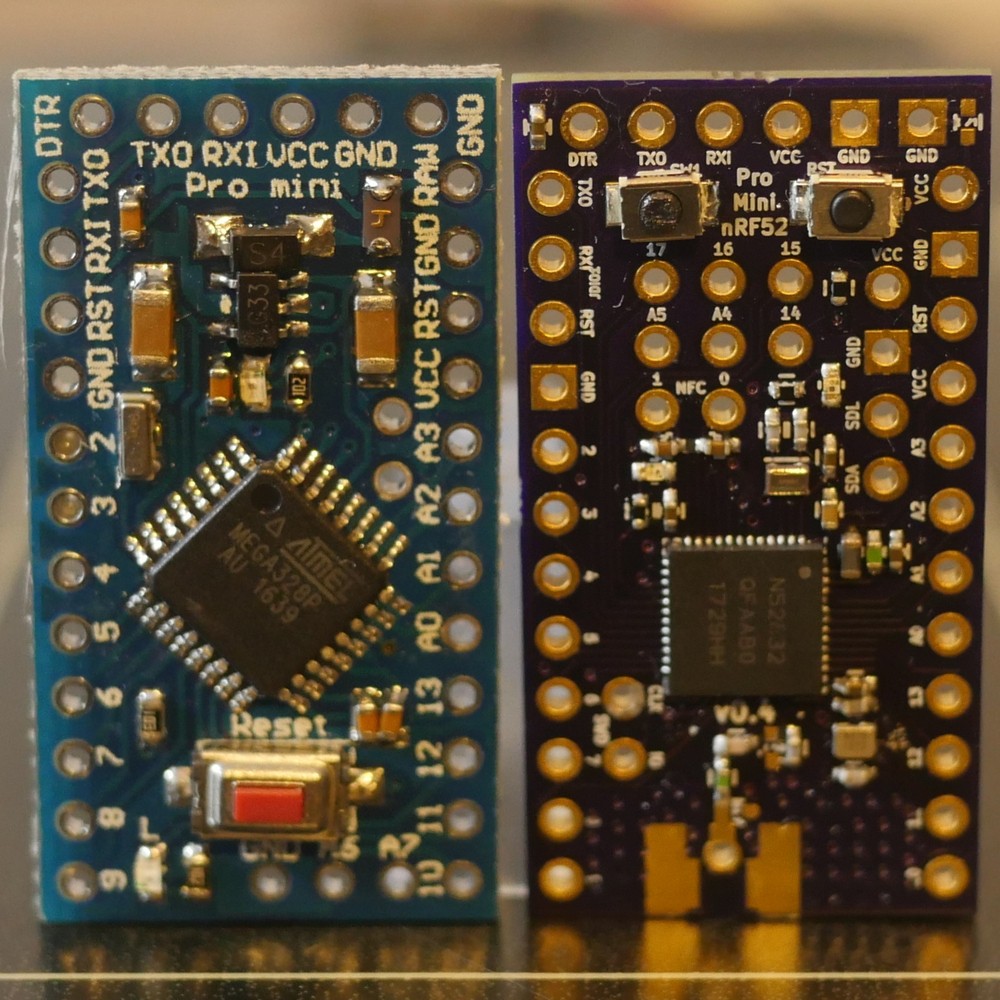
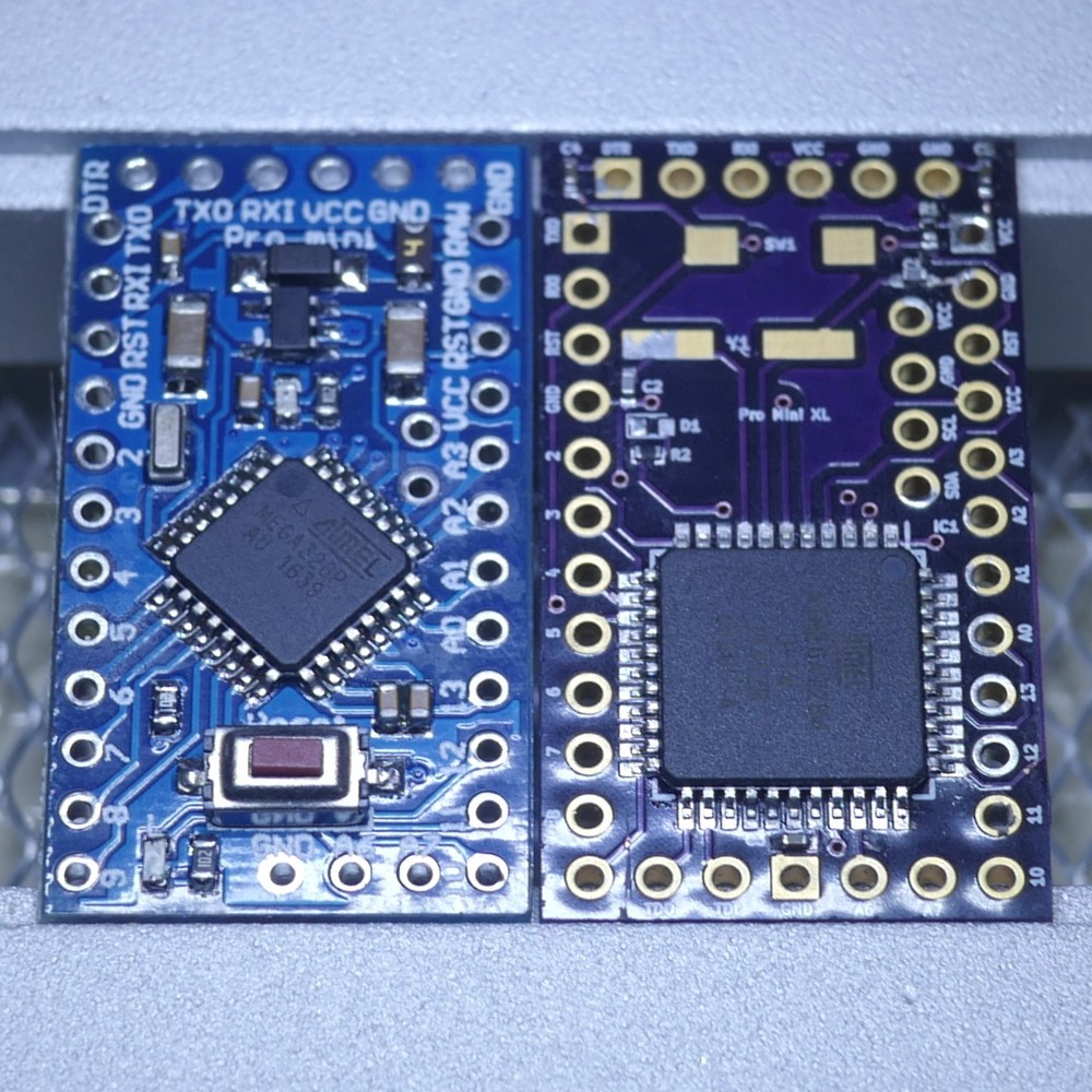
- Benefits or Limitations: The ATmega 328p Pro Mini
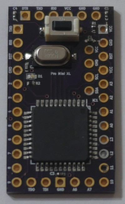
- 8-Bit Bigger Brother: The ATmega 1284p Pro Mini XL
- 32-Bit & Wireless: The Pro Mini nRF52
I’ve written some preliminary project logs and provided quick links to them above.
If there is enough interest in what I’m doing here, I plan to update the list as I post more.
This should help you navigate around the project.
Future Project Logs?
If there’s not sufficient interest, I’ll have to redirect my labors elsewhere.
So with that in mind, I thought I would ask you first what you wanted to hear more about.
Some suggestions to get you started:
- Using the Pro Mini XL & nRF52 with MySensors for Home Automation
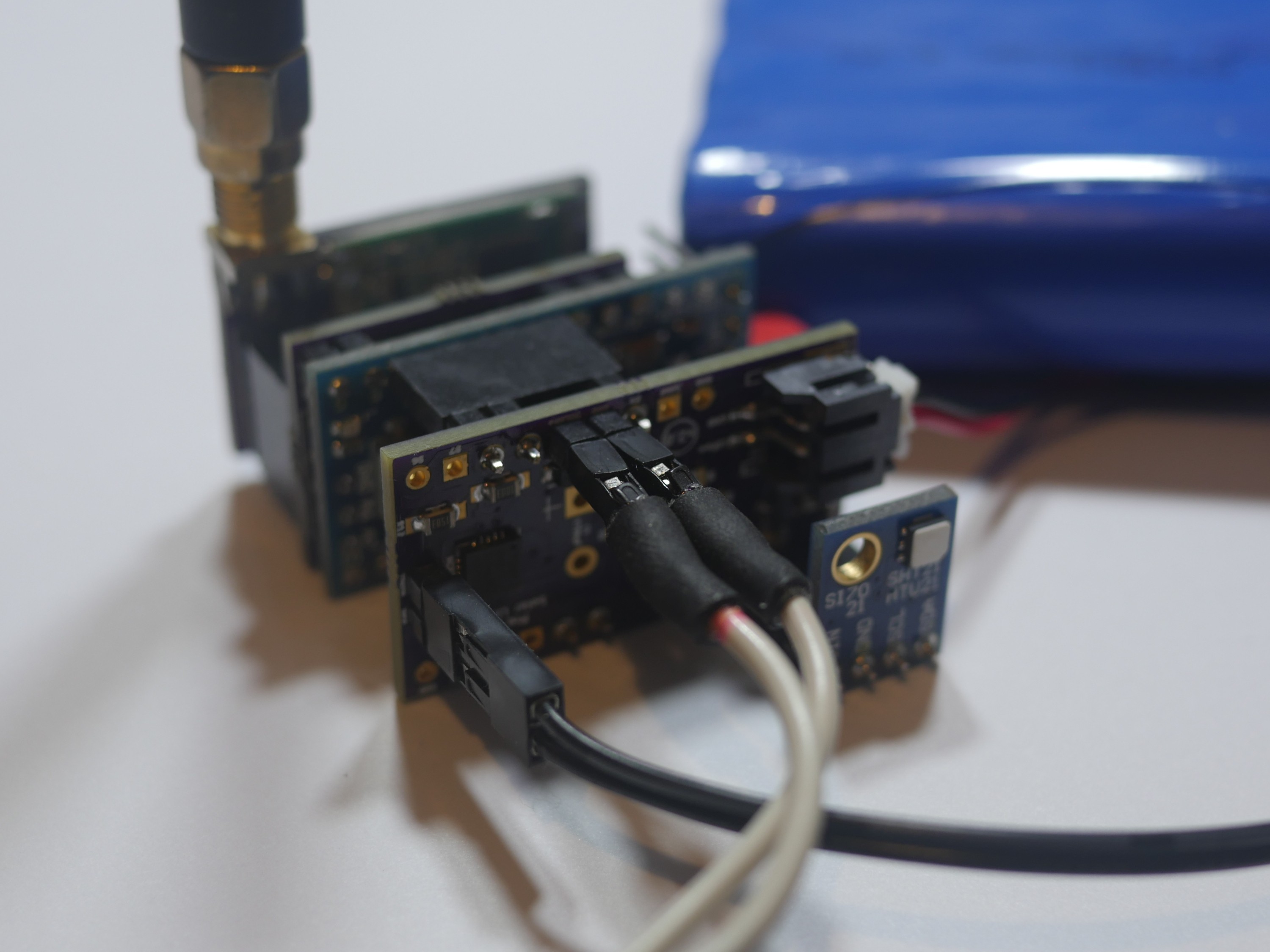
- Pro Mini nRF52 + e-Paper + SI7021 = Low Power Wireless Environment Monitor with Display
- Building an Endurance Quadcopter with the Pro Mini nRF52
- Board Stacking the Pro Mini XL with SPI Flash, ATSHA & RFM69HW
- Unlocking, Debugging & Developing with the nRF52832 using a Blue Pill BMP
- A Pro Mini STM32?
- A Pro Mini SAM?
- Something else?
Rather than (potentially) balloon the comments section of this initial page, please head-on over to this Google Form and let me know what you want to hear more about there.
Where Can I Buy...?
I’ve had a few eager people buy some of these boards from me - even though they’re still in development.
If you’d like to join them, please let me know and surrender an email address here. No spam. Promise!


 Savo
Savo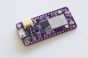
 Jared
Jared
 Patrick Van Oosterwijck
 alnwlsn
Hello Andy. Good work here!
I am (slowly) working on some HA things as well and went through some similar decisions and options as you did, so maybe it helps: http://www.electrobob.com/1000-1000-hardware/
My experience is that best way is to have a sub GHz radio and a micro with sufficient memory so you can include a lot of things, even OTA bootloader. I set on the SAMD21 and RFM69 and is is working a lot better than the low power 2.4GHz radios. And quite few always on powered things I run on ESP8266/32.
Considering the NRF52 i found this project interesting https://www.instructables.com/id/LoRa-Tooth-Small-Wireless-Sensors/