 Matej Nogić
Difference between other POV devices on market
One of the most important characteristics is that the displayed graphics doesn’t depend on rotation velocity thanks to its innovative solution for keeping the track of rotation angle. Meaning that the displayed graphic is perceived the same at both, higher and lower rotational speeds (for instance, when the fidget spinner is slowing down when held in the hand).
This is also one of the main difference between various POV device on the market (POV clocks, etc.) which must have a constant rotational speed in order for the image to be displayed correctly.
It is also worth noting that all the components are selected to have the lowest possible energy use in an effort to prolong the battery life


Technical Description

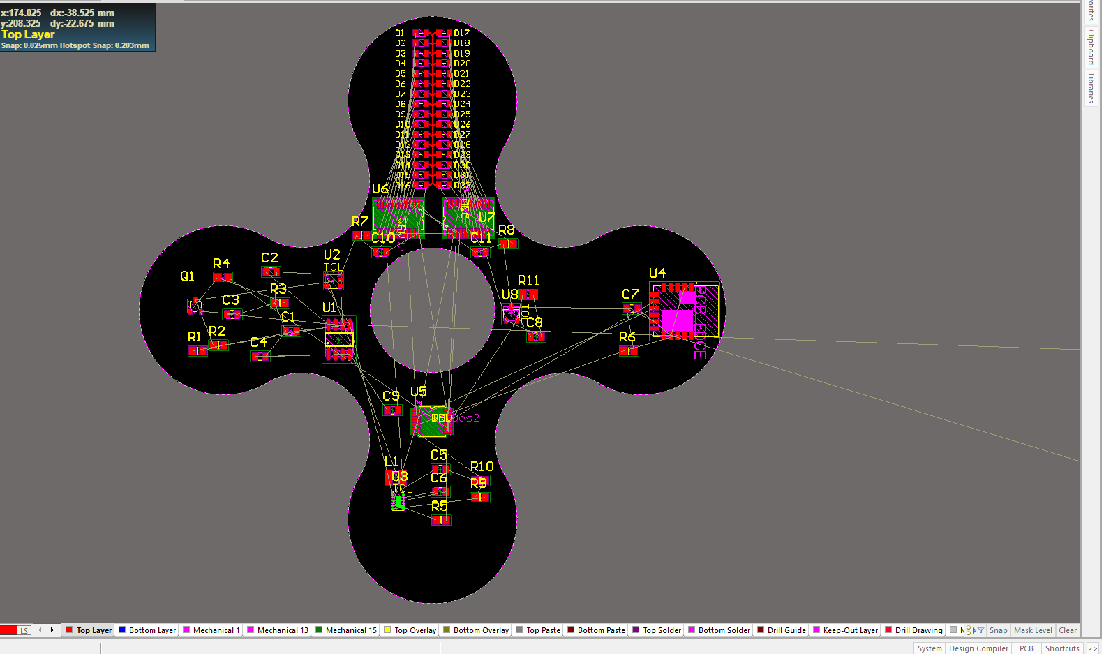
It uses enhanced Microchip PIC 16F1619 microcontroller as its core. The MCU has built-in Angular Timer peripheral which uses omnipolar Hall sensor DRV5033 and one magnet to keep the track of current rotational angle.
The graphics is displayed using a total of 32 LEDs, 16 green and 16 red light emitting diodes (nominal current 2mA). The diodes are driven by two 16 channel constant current shift register drivers TLC59282 connected in daisy chain.
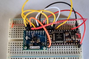
In order to have a remote access to the device, there is a Bluetooth Low Energy module RN4871 which communicates to the microcontroller via UART interface. The device can be accessed from either a personal computer or a smartphone.
The device is turned on by using a capacitive touch button which is embedded under the solder mask on the printed circuit board. The output from the capacitive IC PCF8883 is fed to the OR logic gate BU4S71G2. The other input to the OR gates is a signal from the MCU. The output from OR gates is connected to the Enable pin of a step-down converter TPS62745. By using this setup I am able to power on/off the device by using only one touch button.
Capacitive button can also be used to change between different modes of operation or for instance to turn on the bluetooth radio only when needed in order to save energy.

Step down converter TPS62745 converts 6V nominal from the batteries to a stable 3.3V. I have choose this converter because it has high efficiency with light loads, low quiescent current, operates with a tiny 4.7uH coil, it has integrated input voltage switch which I use to measure battery's capacity with minimal current consumption and the output voltage is user-selectable by four inputs rather than feedback resistors (reduces BOM). The device goes to sleep automatically after 5min of inactivity. The current consumption in sleep is less than 7uA.

The batteries are located on the back:

Keeping the track of rotational angle
The rotational angle is tracked "by hardware“ rather by software meaning that the CPU has a lot more time at its disposal to do other tasks. For that I have used Angular Timer peripheral which is built into the used microcontroller PIC 16F1619.

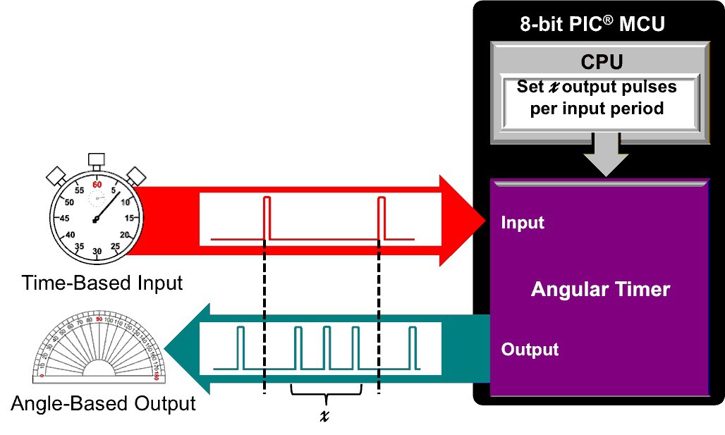
Input to the Angular Timer is a signal from Hall sensor DRV5033. The Hall sensor will generate a pulse every time a magnet passes by it. The Hall sensor is located at the spinning part of the device while the magnet is located on a static part for which the user holds the device. Since I used only one magnet that means that the Hall sensor will produce a...
Read more »


 brian bloom
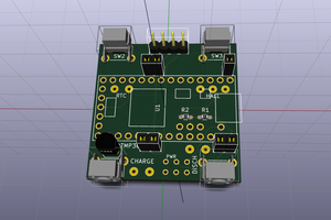
 Matias N.
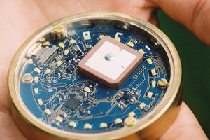
 Antoine Pintout
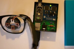
 Malte
Malte
Would you be willing to include the complete BOM?