In this simple circuit we are building 555 Timer IC based Code Lock. In this Lock, there will be 8 buttons and one needs to press specific four buttons simultaneously to unlock the Lock. The 555 IC is configured as a Monostable Vibrator here. Basically in this circuit we will have an LED at the output pin 3 which turns ON when trigger is applied by pressing those specific four buttons. LED remains On for some time and then turns Off automatically. The On time can be calculated with this 555 monostable calculator. LED represents the Electric Lock here which remains locked when there is no current and gets unlock when current passes through it. The combination of specific four buttons is the “Code”, which needs to open the Lock.
This project is sponsored by LCSC. I have been using electronic components from LCSC.com. LCSC has a strong commitment to offering a wide selection of genuine, high quality electronic components at best price. Sign up today and get $8 off on your first order.
Circuit Explained!
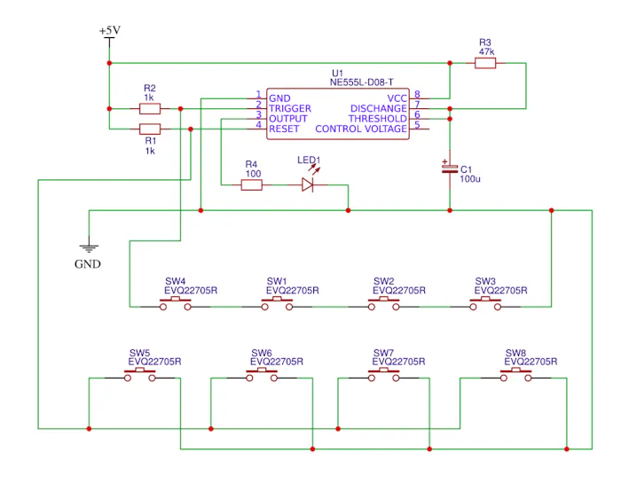
As shown in the circuit we have a capacitor between PIN6 and GROUND this capacitor value determines the turn on time of LED once a trigger is passed. This capacitor can be replaced with higher value for more Turn On time duration for a single trigger. With decreasing the capacitance we can decrease the Turn On time after a trigger. The supply voltage applied in the circuit can be any voltage from +3V to +12V and it must not exceed 12V doing so will result in chip damage. Rest of the connections are shown in the Circuit Diagram.
How it works?
As mentioned earlier, here 555 IC is configured in Monostable Multivibratior mode. So once the trigger is given by pressing the Push Button, LED will turn ON and output will stay HIGH until capacitor connected at PIN6 charges to the peak value. The time for which the OUTPUT will be high can be calculated by the below formula.
T = 1.1*R*C where, R = 47k ohms and C = 100 uF
So according to values in our circuit,
T = 1.1*47000*0.0001 = 5.17 seconds.
So the LED will be ON for 5 seconds.
We can Increase or Decrease this time by changing the capacitor value. Now why this time is important? This time duration is the time for which the Lock will remain open after entering the correct code or pressing the correct keys. So we need to provide sufficient time for user to get enter through the door after pressing correct keys.
Now, we know that In 555 timer IC, no matter what the TRIGGER is, if the RESET pin is pulled down the output will be LOW. So here we will use the Trigger and Reset pins to build our Code Lock.
As shown in circuit, we have used Push Buttons in the jumbled way to confuse the unauthorised access. As in circuit, the TOP layer buttons are “Linkers”, they all need to be pressed together for the TRIGGER to be applied. The BOTTOM layer buttons are all RESET or “Mines”; if you press even one of them the OUTPUT will be LOW even if LINKERS are pressed simultaneously.
Note here that Pin 4 is the Reset Pin and Pin 2 is the trigger Pin in 555 timer IC. Grounding Pin 4 will reset the 555 IC and grounding Pin 2 will trigger the output to be high. So to get the Output or to open the Code Lock, one must press all the buttons in the TOP layer (linkers) simultaneously without pressing any button in Bottom layer (Mines). With 8 buttons we will have 40K combinations and unless the correct LINKERS are known, it will take forever to get the correct combination to open the Lock.
Now, lets discuss the internal working of the circuit. Let’s assume that the circuit is connected on the bread board as per the circuit diagram and given power. Now the LED will be OFF as the TRIGGER is not given. The TRIGGER PIN in the timer chip is very sensitive and it determines the output of 555. A low logic on TRIGGER pin 2...
Read more »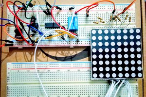
 Hulk
Hulk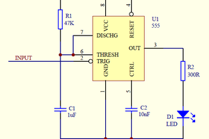
 Klaus Dormann