jed
jed-
9 July - Add the circuit to the robot
07/10/2019 at 04:28 • 0 commentsI need to go back and describe the circuit tailored to ride on the line-following robot. After I proved the concept and selected the alkaline cells to power it, I needed something that could ride on the robot. It needed to connect to the IC socket for its power and to control the motors, and it had to be able to hold the display. I decided to use a strip board and to stack the OLED on top of the NodeMCU. The strip board would plug into the IC socket and the other parts would plug into it. The wiring is pretty simple, so I planned it on in a notebook then wired it all up. Note the OLEDs in my stash sometimes swap the positions of the V+ and Gnd connections. Watch for that.
![]() I used stripboard with male header pins to extend into the IC socket and five wires. Two red are V+, two black for Gnd and a green for a signal wire. The stripboard helped make the connections and saved me a few horizontal wires that are on the drawing. Note the socket on the left, for the OLED, has a second socket plugged into the first. This stacks the OLED above the NoteMCU.
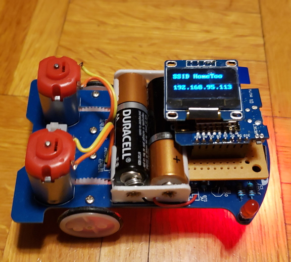
I used stripboard with male header pins to extend into the IC socket and five wires. Two red are V+, two black for Gnd and a green for a signal wire. The stripboard helped make the connections and saved me a few horizontal wires that are on the drawing. Note the socket on the left, for the OLED, has a second socket plugged into the first. This stacks the OLED above the NoteMCU.![]() Once I had it properly installed into the robot's single IC socket, we have this familiar picture:
Once I had it properly installed into the robot's single IC socket, we have this familiar picture:![]()
-
5 July - Adapting to UDP Joystick's format
07/05/2019 at 20:53 • 0 commentsSo I found an Android app that will send UDP to my address based on the position of an on-screen joystick. That is GREAT! See previous (4 July) entry for details.
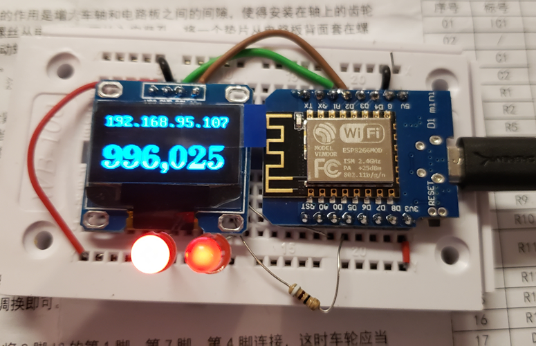
The problem with the app is that it sends its own range of numbers with no tailoring except direction and centering. That means that the program that runs in the ESP8266 NodeMCU needs to change. The "complete" ESPLineMouse.ino turns into ESPLineMApp.ino. The process of turning the joystick position numbers into PWM duty cycle numbers for the motors also needs to move there. The monitoring code left in the application means that I can test at my desk without the robot. I go back to this configuration:
![]()
This gives me everything I need to develop and test. The brightness of the LEDs shows the duty cycle that the motors would see, so I can even test that!
A bit of work and ESPLineMApp.ino is performing well. I'm posting it now.
Now that I've changed the protocol that the target NodeMCU expects to match what the Android UDP Joystick app sends, I also need to change my test shell script AND my web page's backing CGI script. To make this easier, I find CGI.pl and add it to my Pi's library. It just takes "apt-get install cgi.pm" and apt-get figures it all out.While I'm at it, I enhance the CGI to retrieve the target IP from a table based upon the IP of the requestor. I also add a simple page to set that target and another to list all the table entries. Old fashioned Perl CGI.pl makes it easy, for an old fashioned programmer.
The original sendudp.sh becomes sendudp2.sh below#!/bin/bash -x IP=192.168.95.111 # test sending UDP packet (only in bash) in UDP Joystick format # halfway up right side echo -n "1996162515001500" >/dev/udp/$IP/4949 sleep 3 # top near center echo -n "1596195515001500" >/dev/udp/$IP/4949 sleep 3 # joystick neutral position echo -n "1500150015001500" >/dev/udp/$IP/4949 #Mouse.html only changes the name of the cgi it calls to set the IP address of the target. This is now filled in with something real - ipinput.html. Once an IP is input, ipinput.html uses setip.cgi to add it to a table and return a screen. After setting, you have a chance to list the whole table using ipdump.cgi. To get all this to work, I added a directory for the datafiles called /var/www/cgi-bin/datafiles and changed its ownership with chown www-data.www-data datafiles. That permits the CGI scripts to write there.
Now to post the new and changed files.
-
4 July - I found an app!
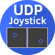
07/04/2019 at 15:35 • 0 commentsAs I mentioned before, I'd like to find an app for android already available that I could use to control these robot cars. I think I've found one! When I searched the Play Store for UDP joystick, I found several possible solutions. I installed a couple, then this one:
![]()
Since my current mouse program still has all the debug console print statements in it, I plugged it into the Arduino IDE and, under tools, started the serial monitor. When I reset the NodeMCU it showed:
Connecting to HomeToo
.
WiFi connected
IP address: 192.168.95.111
UDP connected
Then I installed this app on a tablet and set the Destination IP to 192.168.95.111, the port to 4949, the Send Delay [ms] to 200, and turned the OFF button to ON. I started to receive packets like these:
Received packet of size 16
1500150015001500

Received packet of size 16
1500150015001500

Received packet of size 16
1500150015001500

Received packet of size 16
1500150015001500
I can deal with these! I turned the app back off.
The app has more options. Under Settings, I checked all the boxes for "Center On Release". Next, I turned the app on and pressed the JOYSTICK button. It showed me the screen with two simple joysticks. The values they were sending were displayed at the top. As I moved the joysticks around, those values changed and I could see in my serial monitor that the NodeMCU was seeing those same values:
Received packet of size 16
1500150015001500

Received packet of size 16
1511148115001500

Received packet of size 16
1510138915001500

Received packet of size 16
1510132015001500

Received packet of size 16
1493122915001500

Received packet of size 16
1503117315001500
The center position sends 15001500 for each joystick. The values vary from 1000 to 2000 in each direction. There are buttons under settings to change directions. I'll make the maximum 2000 and the minimum 1000 in both directions. The top will be 2000, as will the left. That should be easiest to keep straight in my head.
Now all I need do is change ESPLineMouse.ino into ESPLineMApp.ino and process and display these packets. I'm freed of the need to write my own app!
Independence Day! -
July 2 - First phase of project mostly complete
07/03/2019 at 05:54 • 0 commentsToday I've posted the code that runs the line-following robot, called ESPLineMouse.ino. I've also updated sendudp.cgi to make sharper turns. Now I can drive my mouse quite well on a bare floor using only a web browser.
That makes this phase of the project a success! I still need to enable multiple concurrent cars to be driven by allowing some way to specify the IP address of the target car. At boot, the cars DO display their IP address (THE major reason each needs a display), but as of yet there is no way to USE that IP except to edit the cgi script on the server.
I can think of two ways to fix this - my original plan was to store the IP in a hidden field of the web page and send it with the touch coordinates each time. It looks like that won't work - I don't see how to process both the coordinates AND read the IP. A second way is to have the cgi routine use the IP address of the requestor to look up the address of the target. The requestor would set that address and the cgi routine would remember it. That seems pretty easy, now that other things are working.
Now for the problem - once our week together is done, my grandchildren will go to home. That's bad enough, but they won't have a web server to run the cgi and let them drive their cars. THAT is unacceptable! Six of them live over 500 miles away, too. I need a way for them to drive the cars at home. This is the problem that I alluded to earlier and still needs to be solved.
It looks like I need a hand-held UDP source. I again have two solutions in mind. 1) an app, either one I can find (better) or one I write (not my favorite). 2) another piece of simple hardware, perhaps a joystick attached to another NodeMCU. It would need a power source and a display and everybody would need one. Approximate cost: NodeMCU $5, display $3, case, battery and holder, joystick $2 = about $15 each. I'd rather not spend the money.
IP control for inexpensive line following robots
A project for my grandchildren to first build line-following robots then convert them to being controlled by their phones and tablets.
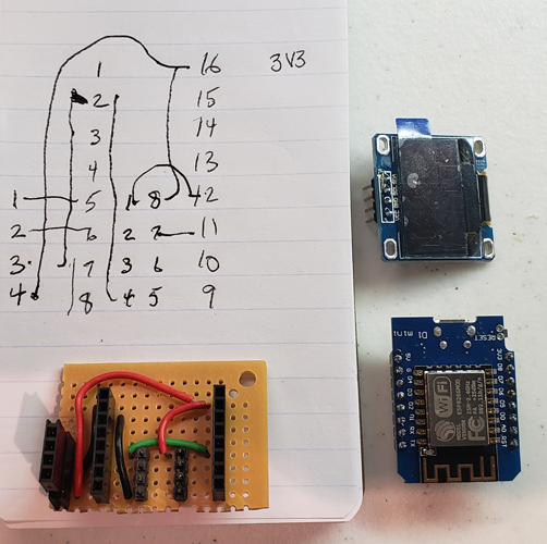 I used stripboard with male header pins to extend into the IC socket and five wires. Two red are V+, two black for Gnd and a green for a signal wire. The stripboard helped make the connections and saved me a few horizontal wires that are on the drawing. Note the socket on the left, for the OLED, has a second socket plugged into the first. This stacks the OLED above the NoteMCU.
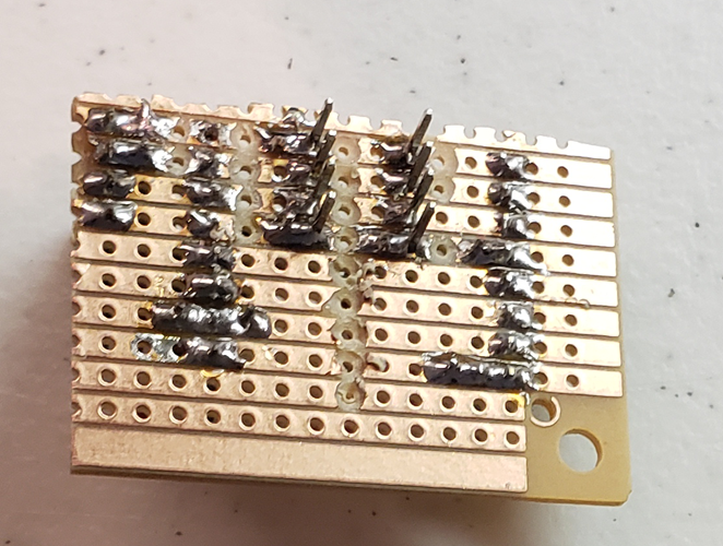 Once I had it properly installed into the robot's single IC socket, we have this familiar picture: