Close
0%
0%

IP control for inexpensive line following robots

A project for my grandchildren to first build line-following robots then convert them to being controlled by their phones and tablets.

jedjed
Similar projects worth following
I have nine grandchildren, ranging in ages from 5 to 17 and ranging in hacking ability from none to taking First Place in the STATE Science Olympiad.

I wanted a project that could be interesting to ALL of them. I wanted it to be short enough to complete for even the no-attention spans of our most connected youth.

I'm hoping this is it.

Project Goals:

. Interesting for at least most of the grandchildren
. Quick enough to be completed during our summer week together
. Not too expensive, since 9 * (expensive) = prohibitive and I need one for myself, too
. Simultaneous control to allow racing - necessary to get the interest of some

Simply building a line-following robot would probably interest between three and five of the nine grandchildren. Adding the ability to control them with a phone or tablet and then to RACE them against each other will probably get the rest involved.

So, what sort of control from the tablets and phones? First I considered Bluetooth, but I fear that the multiple robots being controlled by multiple phones over Bluetooth would interfere with each other. Since simultaneous control is a MAJOR goal, that is OUT.

I settled on trying short UDP datagrams that set the state of the robot, with the processor on the robot taking it from there. Any WiFi network could support more robots than could fit into a room, so this seemed a good target.


Digression: UDP - User Datagram Protocol is the text message of the TCP/IP world. No "phone call" , no connection, just squirt out a limited size transport-layer datagram with no promise of delivery. The minimal requirements and overhead are just right for this application.

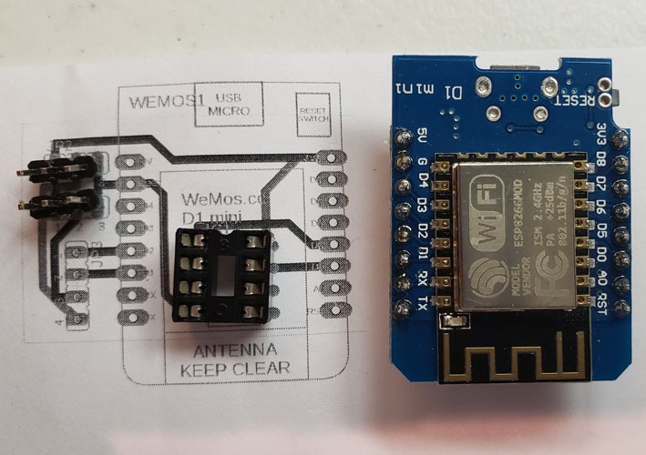
Next I needed to decide on the hardware to be carried on the robot. To me the choice was obvious - some version of the ESP8266. It has all the capability I need in an inexpensive package. I can't use the smallest versions but some ESP8266 Mini NodeMCU version has all the power plus easy implementation that I could ask. I found a three-pack at Amazon for $13 with amazing one day shipping and I found many on eBay for less with not so amazing one month shipping.

Link to single example on Amazon

I purchased samples and started developing.

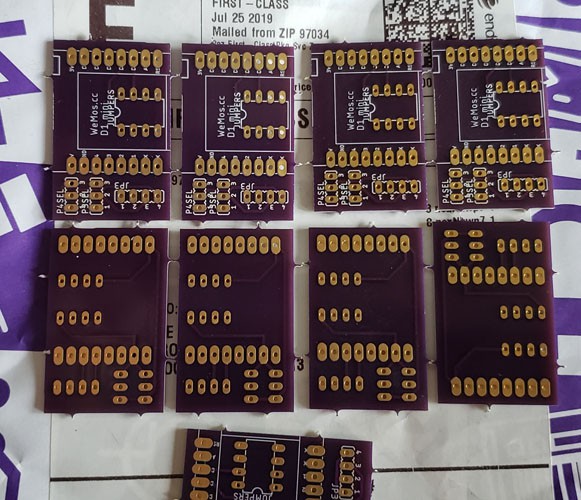
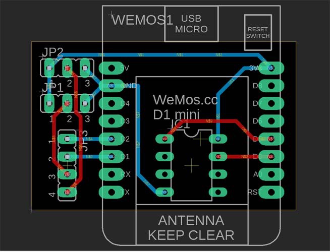
There are various versions of the mini NodeMCU but they all share an onboard 3.3 volt regulator, a USB<->serial conversion circuit, and the various other support circuitry so that they work right out of the box. The ESP8266-12 that they have onboard needs some pins tied high and others tied low before it will load software. It also needs a special "program" lead held high while reset is toggled. The NodeMCU package takes care of all of this for you. The version I use here is best documented at Wemos Electronics.

I use the Arduino IDE for ESP8266 development, so I just started my version 1.8.7 and selected the NodeMCU 1.0 as my target board. That let me look at the Examples and I found (under File>Examples>ESP8266WiFi) a "sketch" called Udp. I nabbed a little code from there and went into "software blacksmithing" mode. I heated it up and pounded on it a bit to beat it into my first test application.

All that application needed to do was:
1) connect to the WiFi network
2) get an IP address
3) display the IP address on the debug terminal
4) loop while
   5) listening for UDP packets and displaying them
   6) interpreting properly formatted packets and displaying the result

The result of this is called ESPlineUDP.ino and is the first program. Since this was only testing communication with the NodeMCU, I needed only to connect one to a USB port on my PC and proceed.

To send test UDP packets, I used a Linux system and the script sendudp.sh. That script is also in the program section, but is so short that it follows here:

cat bin/sendudp.sh  <-- Linux command to display the script

#!/bin/bash -x
IP=192.168.95.107
# test sending UDP packet (only in bash)
echo -n "996,025" >/dev/udp/$IP/4949
sleep 3
echo -n "096,955" >/dev/udp/$IP/4949
sleep 3
echo -n "000,000"...
Read more »

IP-Robot.zip

Eagle schematic and printed circuit board, updated for added jumper 16 Nov 2016

x-zip-compressed - 9.81 kB - 11/16/2019 at 16:04

Download

ESPLMouseAP.ino

Program for ESP8266 running line-following robot. This program watches for 16 byte UDP packets and sets the PWM duty cycle for the two wheels. Latest Final working version, acts as access point independent of other access points.

- 4.54 kB - 11/16/2019 at 16:01

Download

sendudp2.sh

Send test UDP packets to IP address hard-coded in script. These are larger packets than sendudp.sh and match the newer format defined by the UDP Joystack app and used in ESPPackU8X8.

Bourne Shell Script - 336.00 bytes - 09/02/2019 at 21:16

Download

ESPPackU8X8.ino

Program for ESP8266 running line-following robot. This program watches for 16 byte UDP packets and sets the PWM duty cycle for the two wheels. Replaced by ESPLMouseAP.

ino - 6.47 kB - 09/02/2019 at 21:12

Download

count_datagrams.p

Count UDP datagrams and display every second. Written in Perl and tested under Linux Ubuntu and Raspbian.

Pascal Source File - 1.04 kB - 08/29/2019 at 03:54

Download

View all 17 files

  • 1 × Mini NodeMCU Lua hardware, for example WeMos D1 Mini Mini NodeMCU 4M Bytes WLAN WiFi Internet Development Board Base on ESP8266 ESP-12F. To match my pinout, the WeMos D1 Mini is required. Other like boards will have different pinout, so a different carrier would be needed.
  • 1 × 0.96'' OLED Display 0.96'' I2C IIC 128X64 Pixel OLED Display
  • 1 × Line following robot kit Smart Car Intelligent Robot Tracking Car D2-5 Soldering DIY Kit
  • 2 × LEDs with 3V3 current limiting resistor Any LEDs you have on hand with the correct resistors. If you have red LEDs, 150 ohm resistors will be fine.
  • 1 × USB Micro B cable USB 2.0 A-Male to Micro B Cable to attach NoteMCU to computer for programming

View all 8 components

  • 16 Nov - A tiny improvement and replaced program

    jed11/17/2019 at 16:52 0 comments

    Yesterday I said:
    I'm still not quite happy with the display. It shows datagrams received when the change is great but gentle control doesn't show up. This keeps the display from interfering with the car control but doesn't make for good debugging feedback.

    Today I've replaced the program ESPLMouseAP with an improved version. Instead of updating the display when there is a big change between datagrams, it now updates the display when the display itself is much different from the last datagram. This way, gradual changes ARE displayed eventually.

    The display tracks input datagrams much better, without monopolizing the processor. A couple of lines of change and a better result.

    In my next design, I'll know that writing to an I2C display with an esp8266 is SLOW. Using an SPI display takes more pins but should be faster. Something to try.

  • 15 Nov - One improvement made - local WiFi independence

    jed11/16/2019 at 16:19 0 comments

    The last log had possible improvements. This is the first - the car becomes the Wireless Access Point (WAP) itself.

    In the previous designs, both car and controller used local infrastructure WiFi connections. That required the cars' code be compiled for the environment where it was to be used. That could be inconvenient, so now the car acts as an access point that the controller connects to.

    A new jumper can be added to the circuit board that controls the WiFi SSID. No jumper and the name is SSID00. If there IS a jumper, then the SSID becomes SSIDxx where xx varies randomly at each startup between 00 and 99. This allows multiple cars in the same location when required, but requires NO changes to the hardware for only one car and controller. The SSID selected and the car's IP are displayed at startup.

    I'm still not quite happy with the display. It shows datagrams received when the change is great but gentle control doesn't show up. This keeps the display from interfering with the car control but doesn't make for good debugging feedback.

    Still working on it, as time permits.


  • 15 Sept - What now? Two improvements to think about...

    jed09/15/2019 at 23:54 0 comments

    The project as originally conceived works great! Now, what was wrong with that design and how could it be improved?

    The web page was great before I had the app but I've not used it once since. That seems to have been a dead-end.

    Two other things come to mind...

    1) The current design requires both the car and the tablet or phone be connected to the local WiFi network. Adjusting the phone is easy and not a problem. Adjusting the car requires changing the program, then a recompile and reload. Not too convenient.

    2) The current design uses an app. How about hardware with a joystick, for instance, to control the car? That's another idea.

    Two improvements to consider and perhaps work on.

  • 2 Sept - Working code

    jed09/02/2019 at 21:10 0 comments

    I found that the I2C interface is very slow on the ESP8266 (but better on an ESP32). There is NO hardware support for I2C and the interface uses a technique called "bit banging". This is very wasteful of processor resources but needed if there is no hardware support.

    My response: minimize I2C usage. I changed the way the display is handled so that I only paint the part of the display that I'm updating. That is an option that can be selected by the constructor used with the U8g2 graphics library. My original usage was to fill a buffer with the display that I wanted next then transfer that entire buffer to the OLED. Now the program is only sending the parts of the screen that it needs to change.

    In addition, I only display the content of a command datagram when the content is much different than the previous datagram. The datagram display or datagram count (two program actions that can be selected at compile time) are only a debugging aid and not needed to drive the car around.

    One other small change - while the program is trying to acquire a WiFi connection and an IP address, the display is shows "connecting" and the blue LED on the ESP12 itself will flash as it tries to connect. This will show it is running and not powered off. A flaky power switch on my car made this useful.

    Another small change - I removed the car's R5 and R6 51 ohm resistors. These power the bottom LEDs that would light up the lines so we could follow them. Since we are controlling the car directly, this power can be saved. I put pins in the holes from the resistors so that I can plug resistors back on these pins to restore line-following function.

    When I use the UDP Joystick app with the correct IP address (as shown on the display at startup), with port set to 4949, and Send Delay set to 200ms, the car drives easily. I'm very pleased!

    Again, note that in the app configuration I selected "Center On Release" for all four directions and selected Reverse Value for the Left Vertical.

    Final name of this revised version ESPPackU8X8.ino.

  • 31 August - Found a few more datagrams

    jed08/31/2019 at 22:23 0 comments

    On 28 August I wrote that my simple count_datagrams.p found about 85 per second on two different Linux machines BUT the counting datagrams per second code running on my NodeMCU module counted only about 80. I didn't think that important enough to track down.

    Today I tried counting datagrams AND running the line-following robot car. It worked GREAT and I was able to drive it all over the kitchen, controlling it with the app on my phone. It seemed that the delay that I removed fixed everything.

    As a final cleanup, I made put both code sets together in one source module and allowed either function to be selected at compile time. I got clean compiles on both versions of the code then tested. The datagram counting version ran great but the datagram displaying version had the same problem as before - most datagrams were NOT getting through.

    The only addition was the display every packet code. It takes TIME to write to the display every time and that is too much time lost.

    I recompiled the NodeMCU code to again count packets but this time display a two second count instead of a one second count. With the UDP Joystick phone app set to send every 10 ms, the one second count was 80 or 81 but the two second count was about 170. Writing to the display is causing packets to be missed! That accounts for the difference between the Perl code and the NodeMCU code.

    The fix is to not write to the display too much. I should be able to handle that!

    Working version of the code to be uploaded soon.

  • 28 August - Found some missing datagrams

    jed08/29/2019 at 00:15 0 comments

    I changed the ESPLineMApp.ino to add a count of received datagrams. I display that on the OLED instead of the content of the last message. I changed the UDP Joystick app parameter to delay 10ms between packets. That should send about 100/sec but the NodeMCU was only receiving about 17/sec, even when not attached to the line following car. Something somewhere was wrong.

    But where - sender or receiver? One way to tell is with a different receiver. I wrote a simple Perl program to count received packets which I call count_datagrams.p, just to be obscure. I'll upload that soon.

    Interestingly, count_datagrams.p running on an AMD FX(tm)-6300 Six-Core Processor counts about 85 datagrams per second. It does about the same running on a Raspberry Pi 2 B. Clearly the 17/sec shows a problem and also the app isn't really sending 100. Upon examining my ESPLineMApp.ino code closely, I found the last statement in the main loop() is "delay(50)" and I have NO IDEA what I was thinking of when I included that. After I comment out that statement completely, allowing the loop to run at the full speed the processor can do, I find about 80 datagrams per second are being counted. I'm happy with that improvement even though it seems to still miss a few. That could also easily be a result of the overhead of my counting code.

  • 22 August - Failure upon Failure or Life in the Fast Lane

    jed08/22/2019 at 15:34 0 comments

    Yesterday's log entry reported that many (most?) UDP datagrams are not getting through to the car. I then guessed that since the display was closer on the PCB than on the stripboard prototype, it might be interfering with the WiFi signal.

    I tested that theory last night. First I put another socket plugged into the first to increase the distance between the WiFi antenna and the display. NO effect was noted.

    Next I had a great idea - after the display showed the current IP address, I removed it completely and depended on the actions of the car to show me when datagrams were being received. NO effect was noted.

    I'm quite sure that an unattached display is not effecting reception. Therefore I deduced that it must be something else.

    My next candidate is electrical noise from the DC motors. After all, I've taken NO precautions above those built into the NodeMCU module.

    So why did the problems wait until now to surface? That might be the well known real estate answer - location, location, location. My "workshop" is in the basement and just a few feet from the Wireless Access Point (WAP). My tests yesterday were upstairs and much farther away from the WAP. That's one more theory to test and evaluate.

  • 21 August - PCBs arrived, some failures to report

    jed08/21/2019 at 20:54 0 comments

    The PCB boards from OSH Park arrived promptly, but I was out of town. I ordered 16 July and they arrived about 27 July, using only the free shipping option. I assembled one and everything went smoothly UNTIL I tried to use it. The components all fit properly and soldered easily. The boards were exactly as I tried to design them and a delight. A few dollars and a few days let me avoid the all the troubles of etching my own. Again showing that just because you CAN do it yourself does NOT mean that you SHOULD. The knowledge to do it also gives you the knowledge to understand when you shouldn't.


    One change between the stripboard prototype and the PCB, that I mentioned in passing but didn't really explain, was the added jumpers. This picture shows the problem - different suppliers of the OLED displays have VCC and GND pins switched. The jumpers allow me to select which display I'll use this time.


    My first problem with the PCB was that the display was flaky. That turned out that the components on the back of the display were touching the ESP8266 case beneath it. A strip of electrical tape quickly cured that.

    The second problem is more difficult. Most UDP messages are NOT getting through. My first guess is that the display is now closer than in the stripboard prototype. The shorts requiring electrical tape showed that. Perhaps it is interfering with the WiFi reception by being so close. To test that, I need to mount the display higher with longer jumpers. I'll do that next and report here.

    Another failure was in planning the assembly of the "tracking cars". I've found it takes about two hours of concentration for any of the inexperienced grandchildren to assemble a car and that's TOO LONG for some. It took even longer for the first ones, but I have a better procedure now. Also, I should have brought a VOM along to diagnose problems. One car had a joint so overheated that the traces around one lead broke on BOTH sides. I couldn't identify the problem without tools. That was poor planning.

     A positive thing was the weather. Our week together had perfect weather for being outside and ZERO days to be inside. That meant this inside project wasn't needed to fill a rainy day. Since it was NEVER a priority project for our week, that isn't much of a disapointment.

    We ended our week together with three assembled cars, of which two worked correctly. They were assembled in the evenings by those most interested. The third car was fixed with a jumper wire across the two broken traces as soon as we got home.

    We have postponed any races until our next get-together.

    It's been very busy around here, so I'm behind on things - including updating this project. I'm trying to catch up.

  • 16 July - OSHPark order

    jed07/17/2019 at 14:46 0 comments

    One great thing about OSH Park Here is that they take Eagle PCB files directly. There is no need to generate the Gerber files most others require.

    I've uploaded my board and generated an order. My order of 9 copies of my PCB costs $21.15.

    I'm now going to upload the Eagle files here, too.

  • 15 July - Take prototype to PCB with Eagle

    jed07/15/2019 at 21:40 0 comments

    My favorite PCB creation tool for hobbyists is Eagle, now from Autodesk.

    Eagle Overview

    Imagine my surprise when the Eagle I have installed, 5.11.0, has been superseded by 9.4.2. My how versions fly! I downloaded and installed the new version and started to get used to the new interface. Then I took my notebook page (as shown in the last log) and drew the schematic in Eagle. The only hitch was the NodeMCU pinout.

    Fortunately, some kind soul has thought of other Eagle users and published a library containing various ESP8266 layouts. The last update is even the one I want. The commit log says "esp8266modules.lbr    Added WeMos D1 mini module - 3 years ago" and that is EXACTLY what I want.

    ESP8266 Eagle Library download

    I've downloaded that library and used Eagle's library manager to "use" it. Then I finished drawing the schematic to match my notebook and used that schematic to construct a board layout.

    The board matches my stripboard prototype with the addition of two jumpers that allow use of OLED modules that switch their V+ and Gnd leads.

    Once the PCB looks done, I print it actual size and try the parts on it. This lets me check some obvious things like clearances and some less obvious like part mistakes.


    The IC socket is a stand-in but tests fit. I'm happy with it.

View all 14 project logs

Enjoy this project?

Share

Discussions

Similar Projects

Does this project spark your interest?

Become a member to follow this project and never miss any updates