The prototype uses Eurocard sized stripboard for the backplane and 85mm wide stripboard for the daughter boards which can be of any length. Currently the daughterboards are just carriers for prebuilt modules such as the Arduino Mini Pro, the Blue Pill and the RPi etc. It also uses prebuilt modules for the power supplies and voltage level conversion and other functions. The backplane can be cut between any 2 daughterboard locations to provide a smaller backplane. The logic traces can also be cut to provide sub-systems but then board placement becomes fixed.
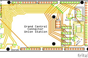
The first image is of a partially constructed unpopulated backplane, the second shows four daughter boards. Clockwise from the top left they are: An Arduino Mini Pro carrier board, A dual 5v/3.3v power supply + bidirectional logic level converter + termination/pullup board, A (now defunct) Intel Edison board with its own logic level converters and a populated Raspberry Pi model B carrier board. The third image shows how the daughter boards fit onto the backplane.
The bus uses 30 pins of single strip 0.1 inch pin spacing connector strip. The electrical bus is a 15 pin bus per voltage level, so the 30 pins have 15 pins for 5v and 15 pins for 3.3v. Future versions will support 2x30 pins and 2x15 pins so that more voltage levels can be supported or a narrower backplane can be used.
The bus is a serial bus that primarily communicates via I2C and SPI. Most other GPIO communication uses separate board to board or board to external device connections.
The pins are as follows, with the first 15 being for 5v and the second 15 for 3.3v:
1) Raw power - specified as 12 to 24 volts DC - input to PSU modules etc.
2) Vcc - 5 volts
3) RS485 serial - originally logic level serial but that wouldn't be shareable
4) I2C - SCL - 5v
5) I2C - SDA - 5v
6) SPI - MOSI - 5v
7) SPI - MISO - 5v
8) SPI - SCLK - 5v
9) SPI - SS1 - 5v - active low
10) SPI - SS2 - 5v - active low
11) GPIO - active low - primary function is SPI SS3
12) GPIO - active low - can be a second interrupt or a 4th SPI SS line
13) Interrupt - active low - hardware interrupt 1 - usually on transition high to low
14) reset - pulled low to reset
15) GND
Pins 16 through 30 are a mirror image of pins 1 through 15 but for 3.3 volt levels. The ground pins (15,16) are common and are digital ground only. Analog signals do not use the backplane. The RS485 pins are logic level independent. The raw power pins can be supplied by the same source or can be separate (e.g. for power supply redundancy). All logic pins are active low unless otherwise stated. Where possible, pullups are provided on an interface board so that the other boards do not need to supply pullups. It is recommended that the SPI SS lines are multiplexed but it is not required.
 bobgreenwade
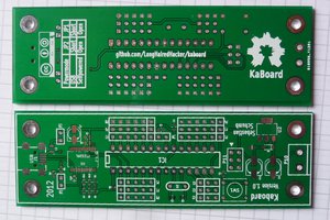
 ar3itrary
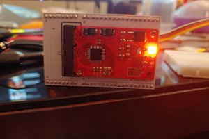
 FloppidyDingo
 Craig Hissett