 Ben Brooks
-
1WARNING!
The first thing you need to know is this is dangerous; proceed at your own risk. The fan is directly wired to 120V and you will be working with this, so be careful and flip the breaker that it is on while you work. If you aren’t comfortable or qualified to work on line voltage, don’t.
-
2Identify your setup
With that out of the way, proceed with identifying how your fan is controlled using a multi-meter. In my case, power is ran through the switches and toggling them simply completes various circuits (the circuits ultimately being the various windings in the motor allowing it to be multi-speed). The actual wires were connected to the switch terminals with spade connectors, so it was quite easy to unplug them (remembering which wires go where). Ultimately, I bought similar connectors (though not quite the same size) at a local hardware store and crimped these to a piece of copper wire for connection to the relays (taking care to use heat shrink tubing to ensure nothing jostles loose). I then connected another set of wires to the buttons using the bought connectors as well. Additionally, I had to splice off the common wire so that each relay could be connected to it (as evidence by the red twist-on wire connector).
-
3Make the board
Beyond printing the components, the only other time-consuming part is soldering up the board. My skills are less-than-great and I didn’t run into any issues. While not the prettiest thing I’ve made, just follow the wiring diagram I made below.
-
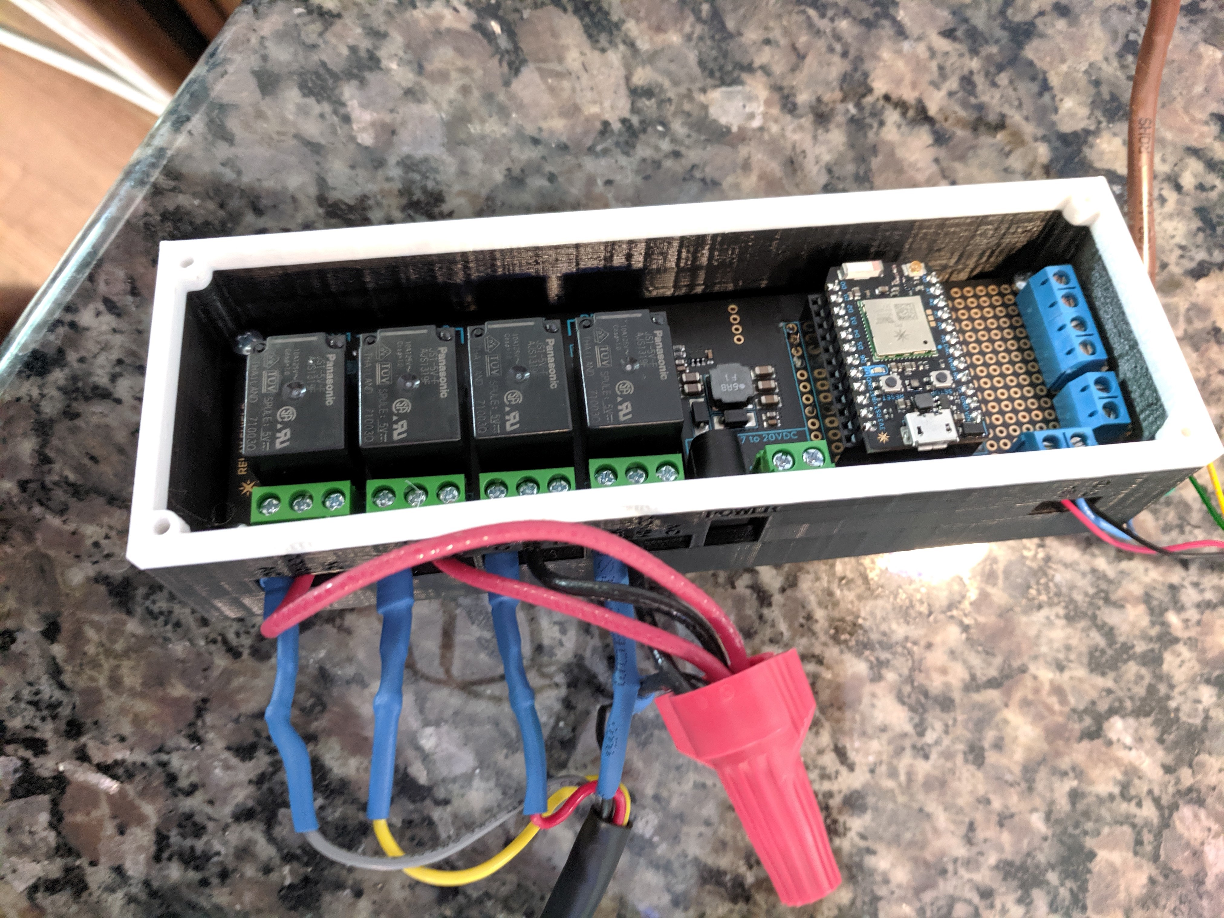
4Assembly
Solder the sensors to a foot or 2 of wire and run them through the wiring hole in the sensor enclosure. After you’ve mounted the relay shield into the enclosure, connect everything up to the screw terminals as-labeled. It should look something like this now:
![]()
-
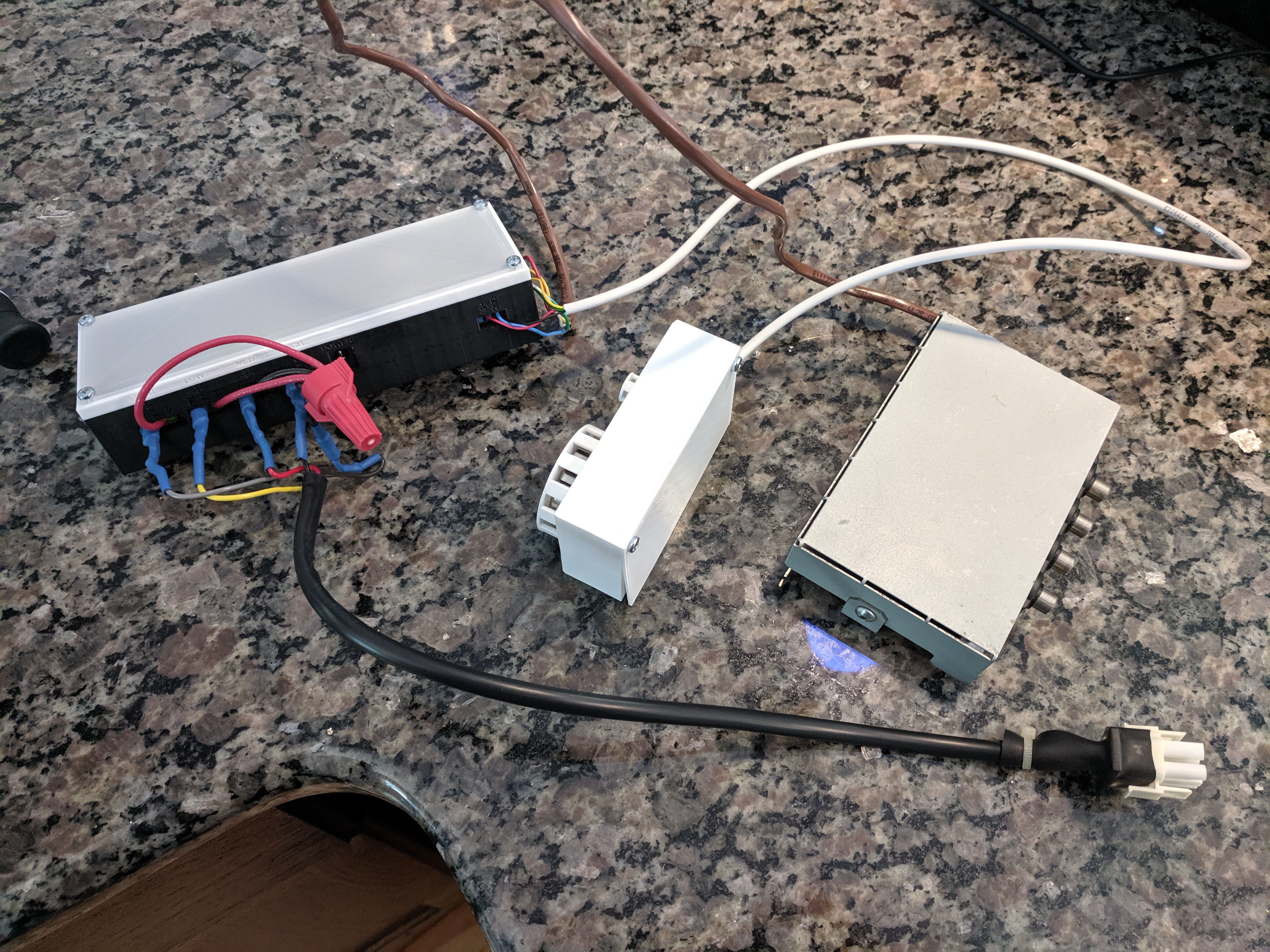
5Wrap-up
Now all that’s left is to put on the covers, connect the various pieces that were removed, put it in the hood area and connect power. I should mention here that I ultimately wired up an electrical plug within my exhaust fan allowing me to connect a transformer to power the relay shield. I specifically did this project in such a way so that if we ever sell the house, it will be fairly easy to remove everything I installed and return the exhaust fan back to its original state.
![]()
-
6Code
The code I wrote is rather simple, and could probably be cleaned up by someone more skilled than myself. It's located on GitHub here. However, it works like a charm for me and I’ve been very happy with the results thus far. I created Particle Variables that you can call to check the current status of the fan as well as the readings of the sensors. In all reality, there’s no reason it needs to be an internet-connected board. However, for the price of the Photon I feel it’s worth it to make troubleshooting/calibrating easier (since no wires are required) and if I ever want to add functionality that would require internet access, it’s right there. For instance, I have internet-connected smoke alarms in my house and I’ve contemplated adding a sequence to switch the exhaust fan to high if the nearest one detects smoke.
Exhaust Fan Controller for Range Hood
Automate your existing range hood exhaust fan, ramping the fan up as-needed based on both temperature above the range and smoke levels.
Discussions
Become a Hackaday.io Member
Create an account to leave a comment. Already have an account? Log In.