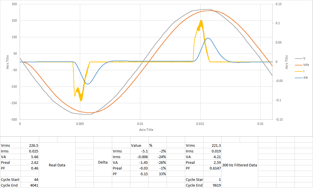
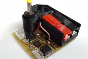
This started with my desire to modify my Kill-A-Watt meter to report power to Thingspeak. Got it mostly working, but still had some offset/inaccuracy issues due to sampling rate (and discovered it was off by a factor of 2 because the original X2 power supply capacitor failed on the Kill-A-Watt). Ended up magic-smoking it while I was programming it so I am now scrapping that to work on a new, from-scratch power meter/IoT switch. First picture in the gallery is the original Kill-A-Watt prototype, second is a vaporized power trace to the KaW op-amp, and third is a magic smoked ADC. Reverse engineered schematic of the Kill-A-Watt circuit can be found here: http://www.mikesmicromania.com/2013/03/kill-watt-circuit-analysis.html
This will have a couple versions:
1. Basic power meter only, records V/I/PF and reports to Thingspeak or similar
2. #1 plus 16A relay for on/off load control
3. #1 plus 10A triac for dimmer control of lamp or motor speed control
4. #2 or 3 with OLED display added for real time view of power usage, kWH or voltage/current waveforms
Instead of being a "brick" that plugs into an outlet, I will be designing this as more of a short extension cord. Doubles as an outlet saver for power bricks that take up lots of space :)
Basic specs:
Voltage: 85-250VAC
Current: 0-16A (relay version), 0-10A (dimmer version)
Power Factor: 0-1
Resolution: 0.2V, 0.01A (high range, 1.6-16A), 0.001A (low range, 0-1.6A)
 mosaicmerc
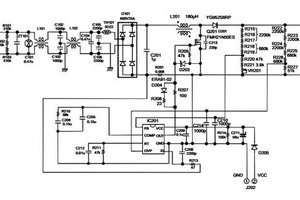
 engineerkid1
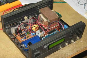
 Hasan Murod
 Electroniclovers123