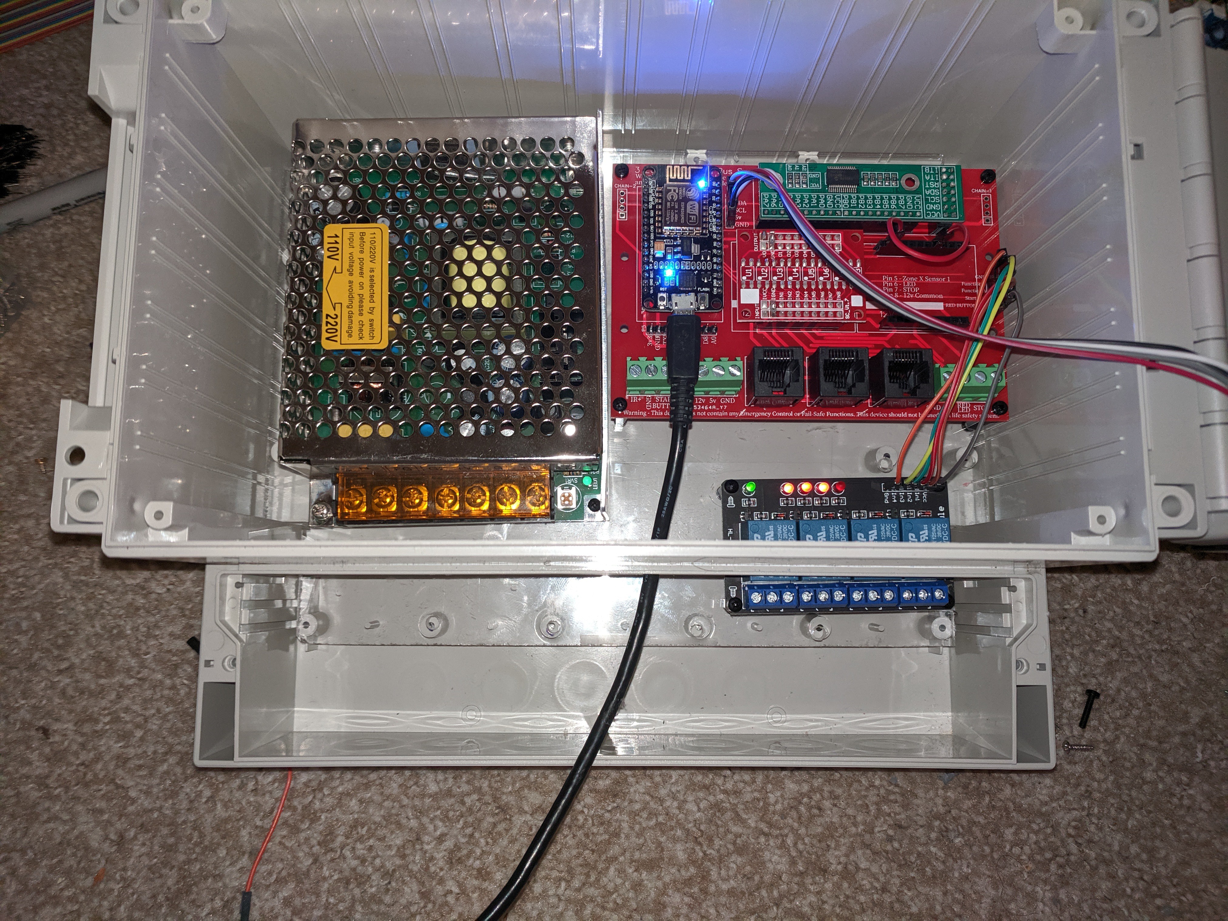
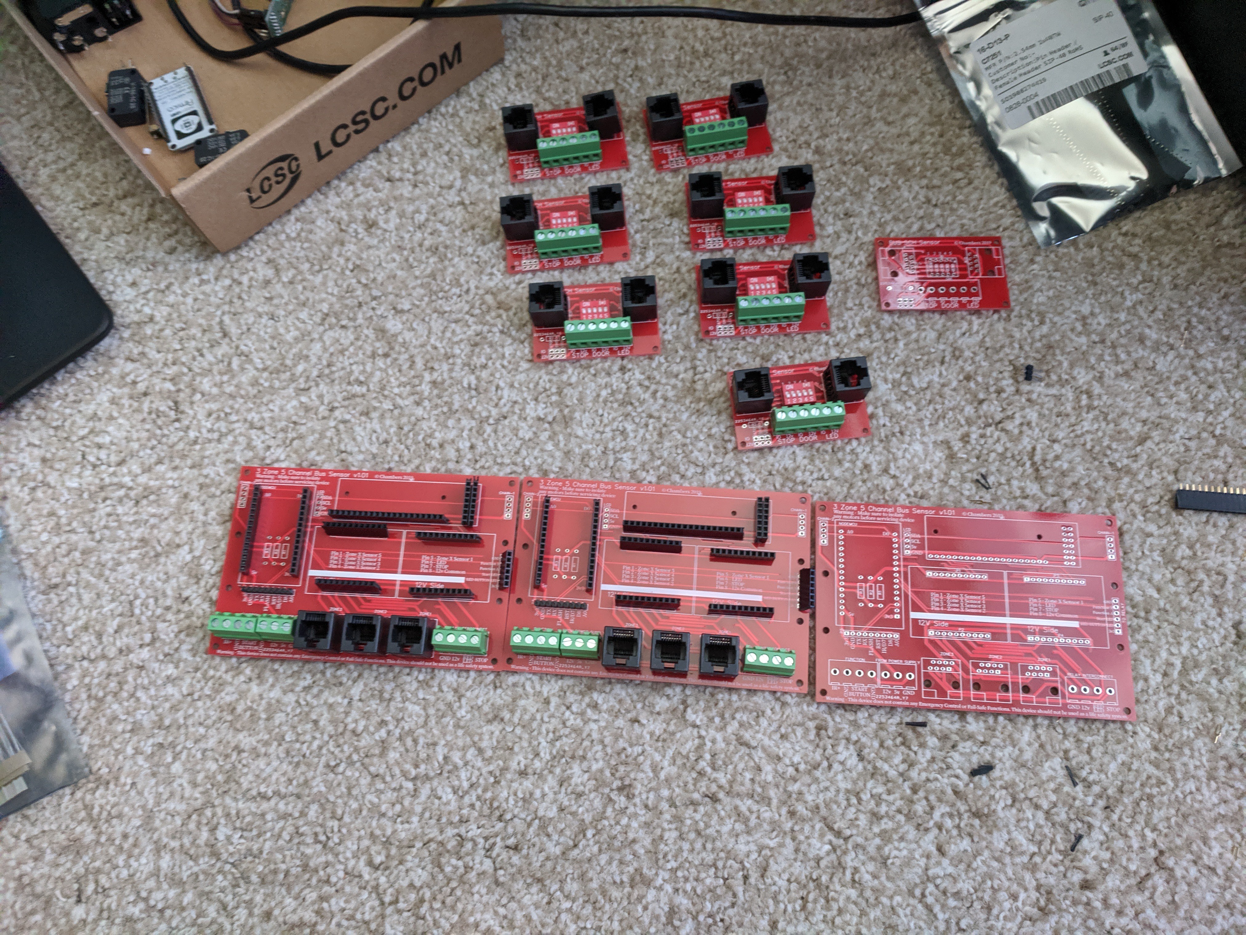
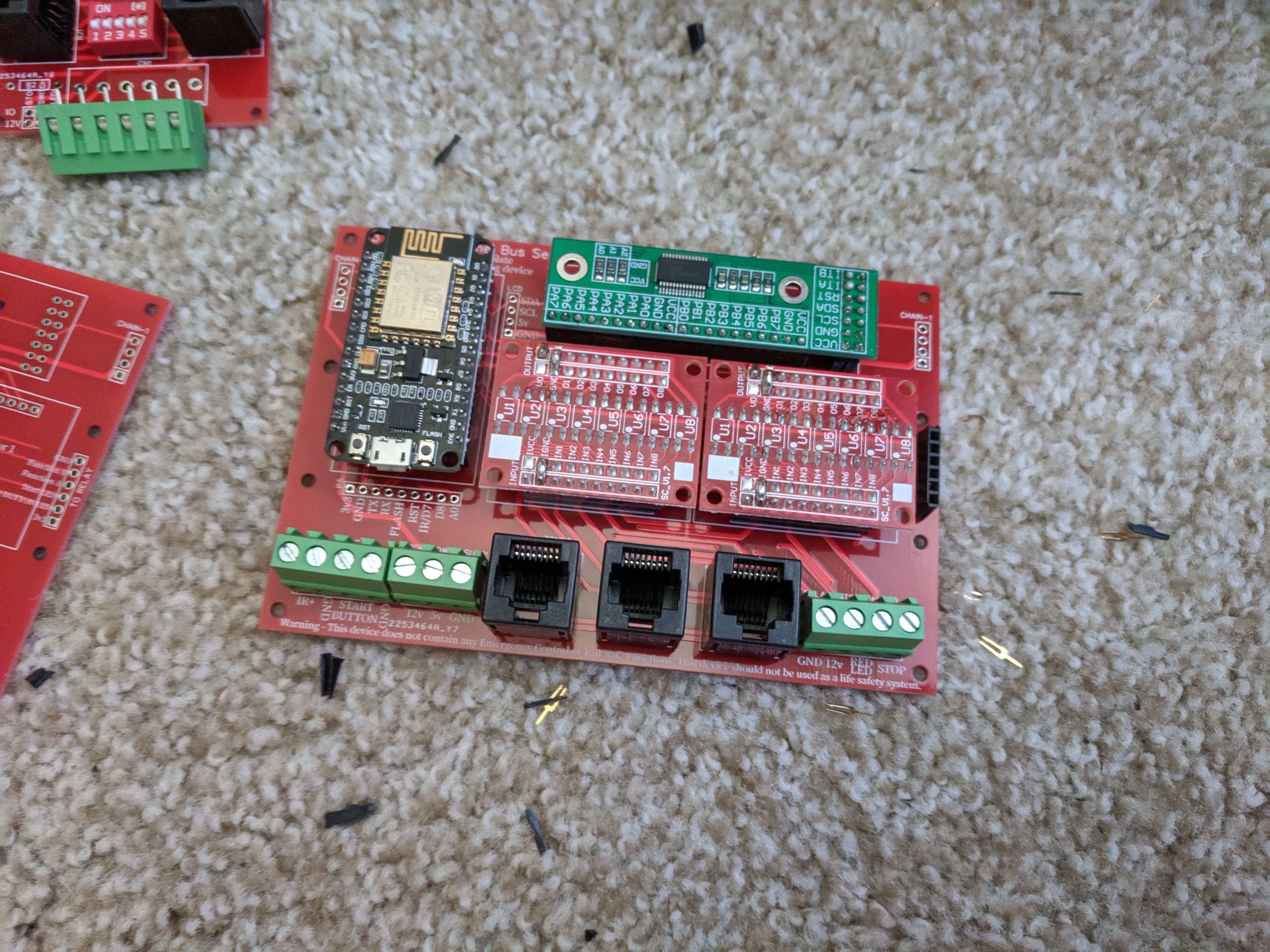
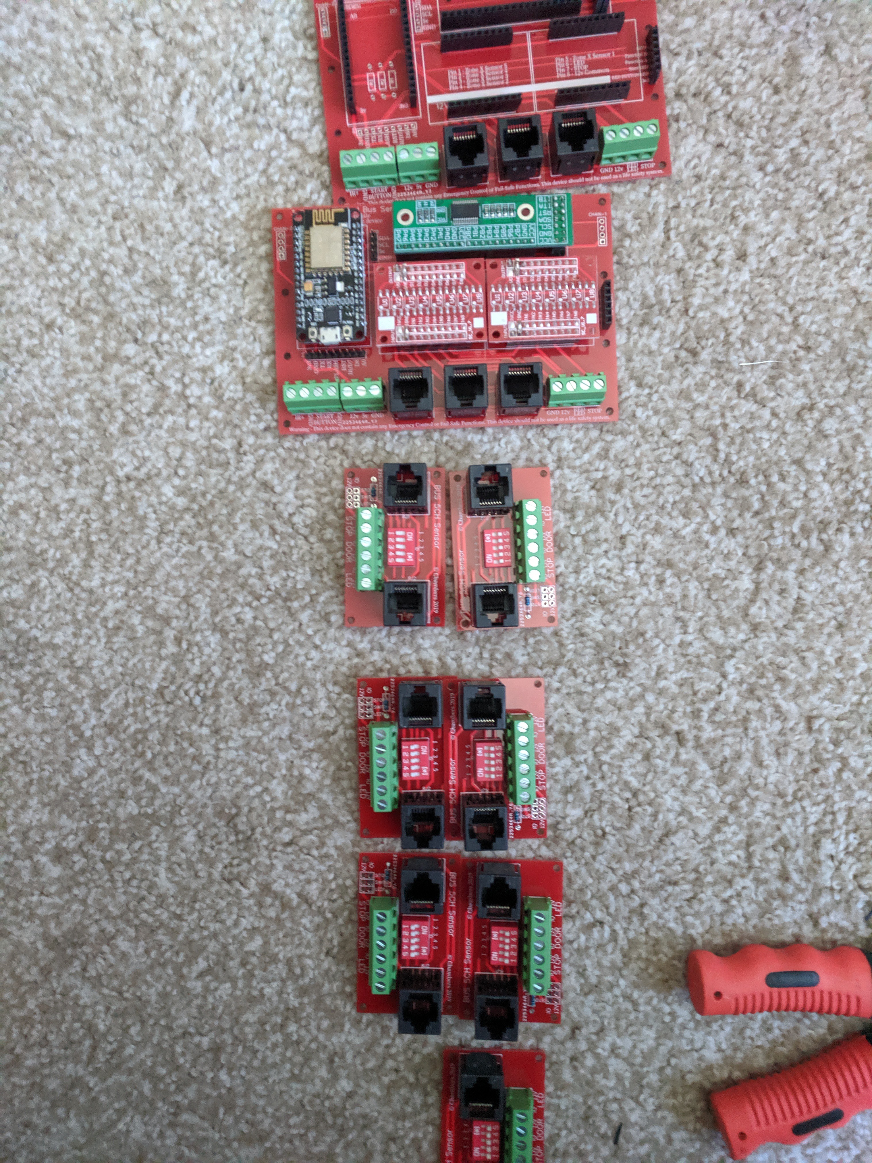
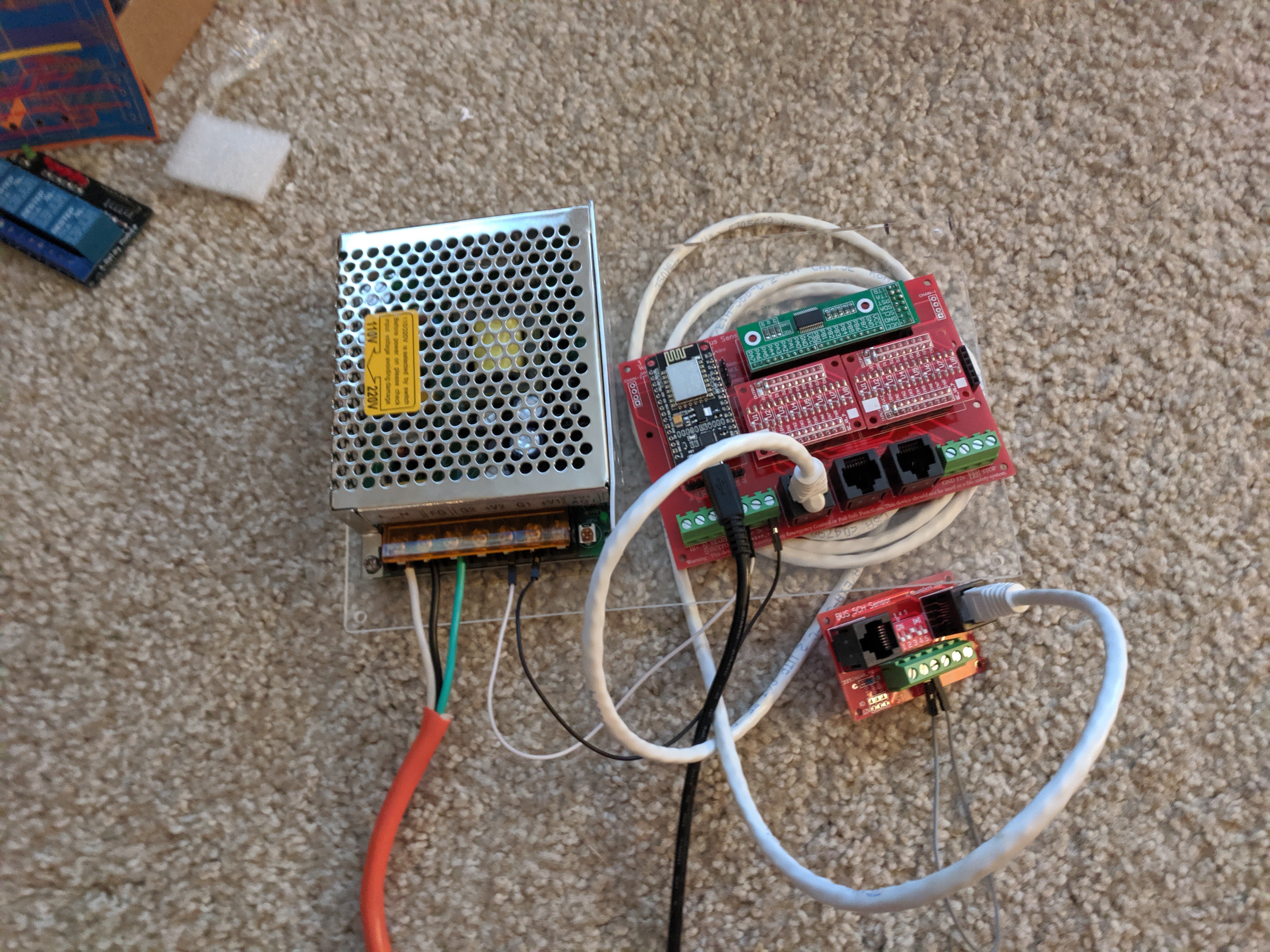
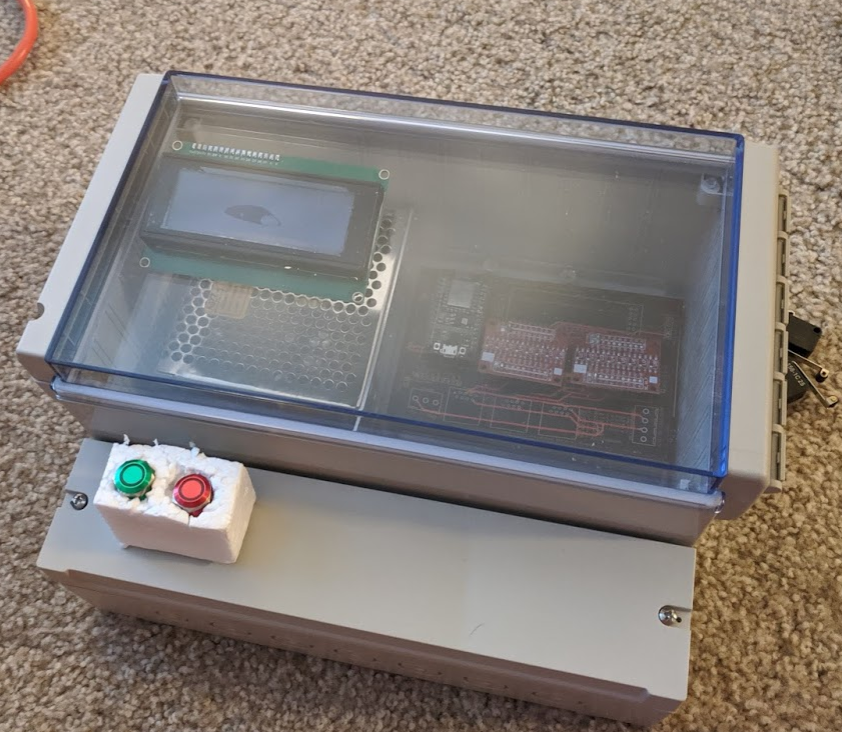
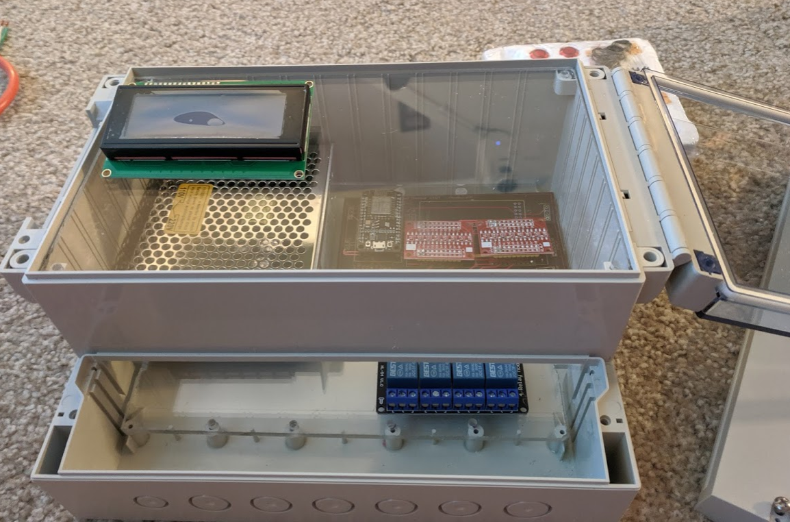
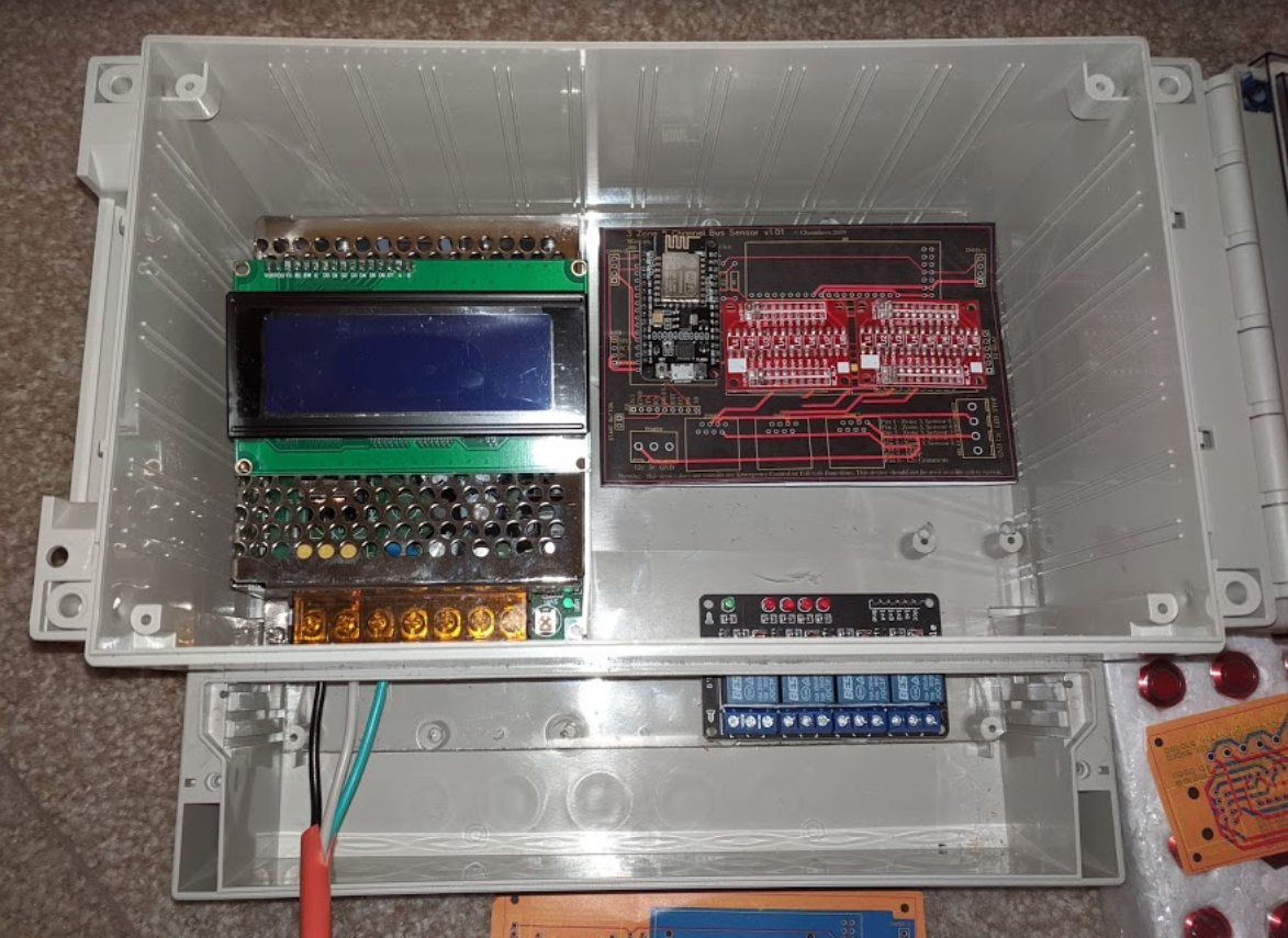
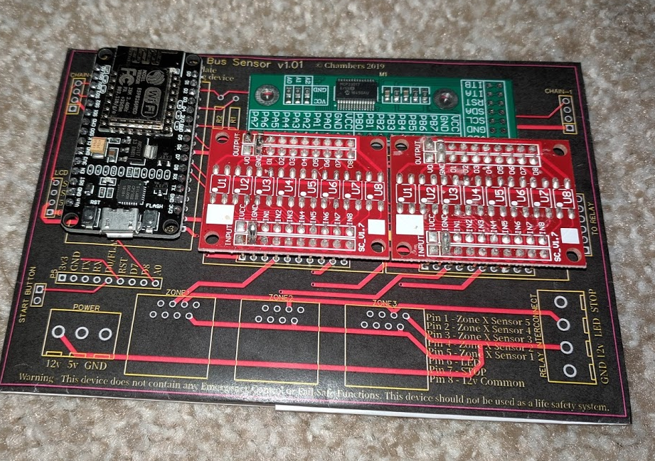
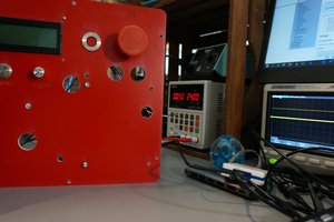
• Coding, Coding and Mounting

    Jason09/19/2019 at 14:47 0 comments

    I took the controller with me on a business trip and spend the night getting the basic code framework out.  It is going to run on top of Arkhipenko’s TaskScheduler. (https://github.com/arkhipenko/TaskScheduler)  This should help me isolate any issues between the different control systems while managing the different task’s timing requirements.  The code will be divided up into 5 major systems with the major systems having some subsystems

    • GPI control/logic – will monitor the inputs and sent internal flags based on their states
      • Sub System – MCP monitor – will check to make sure the MCP23017 chip(s) is responding to command correctly, if not put the system into a failed state.
    • Motor control/logic – will monitor the internal flags and set the relay or IR pules that will control the motor
    • LCD control – will decide what should be display
      • Sub System – LED Display – will perform the LCD updates based on the internal flags of LCD control.  It is in its own task because the LCD is I2C and want it to have the lowest priority and could be missed a few loops if more import task needs to run.
    • Serial Debug – TBD – will be used to debug the system
    • WiFi Web Server - TBD – To control internal settings

    With the logic tested as much as I can in simulation.  When I got home I mounted the PCB, power supply, LCD and relay module to the polycarbonate sheet.  With the devices inside the enclosure, it is starting to look good.  Hopefully tomorrow or the day after I can get the C14 Power plug, Start (Green) button, Stop (Red) button, Config (Blue) button, and USB extender mounted and wired up.

    Hotel room programming:

    Mounted:

  • The Beauty of Red

    Jason09/16/2019 at 00:57 0 comments

    The PCBs has arrived!  I spent an hour assuming 2 control boards and 7 remote sensors.  I needed 2 controller boards so at some point I can test chaining to increase the number of sensors from 3 zones-> 15 sensors to 6 zones 30 sensors.  I am happy to see that so for with some basic firmware, the ESP8266 and MCP can talk to each other and trigger the correct high/low response.  I have begun the process of programming the logic and advanced firmware that will be controlled by the end-user to control the dust collector!

    Staging the headers and and connectors:

    The controller fully populated:

    The first test of the controller:

    Test Zone 1, sensor 1, 4 and 5 (I kept flipping switches to verify it was working on all 5 sensors per zone).  While I forgot to take a screenshot of it working; I am happy it is working as designed

  • Non-Invasive Current Sensor and Servo Control Add-on

    Jason09/12/2019 at 18:08 0 comments

    As I wait for the PCB to arrive, I was thinking of ways to improve the system.  I saw a video of someone using servo and current sensors to automatically control the doors on the collection system.  So I start the process of designing a servo control board that will interface with the existing system. While the design is still only a few days old and untested; I figured it was far enough along to share. 

    Again, this board was designed with a non-electric/computer person in mind.  All the setting would be accessible from the PCB and did not require a PC to set up and managed.  The settings include a 3-way switch to force the gate open, closed or put the system in “Auto Mode”.  5 Pots control versus thresholds.

    • 2 controls the threshold for when the power level is high/low enough to trigger the “On” or “Off” state of the woodworking hardware
    • 2 controls the servo arm’s “High” and “Low” setting
    • 1 controls a delay-off to allow the system to delay the motor off time to allow for additional time to push dust into the collection tub

  • ​ Controller Enclosure

    Jason09/04/2019 at 23:42 0 comments

    With the Bud Industries DCH-11923 enclosure arriving; the first round of layout testing has begun.  Nothing will be set in stone until the PCB arrive so a proper fit can see seen.  But the mock-up seems to fit correctly! :D  System enable/disable (stop) may be mounted outside of the enclosure door but in a spot to not touch the high voltage wiring.

  • PCB Design and mock-up

    Jason09/04/2019 at 20:56 0 comments

    After the parts started to arrive from China, the layout slightly changed.  Somewhere in the process of making sure stuff fit; Zone 1 and 3 ports got swapped (showed correctly in this photo)...   PCB have been ordered before the zone swap was spotted. The v1.01 boards should arrive in the next few weeks then the real fun should start; the programming!