Here's some screenshots of some of the CAD I've been working on over the past month or two, while stuck inside because global viral pandemic.
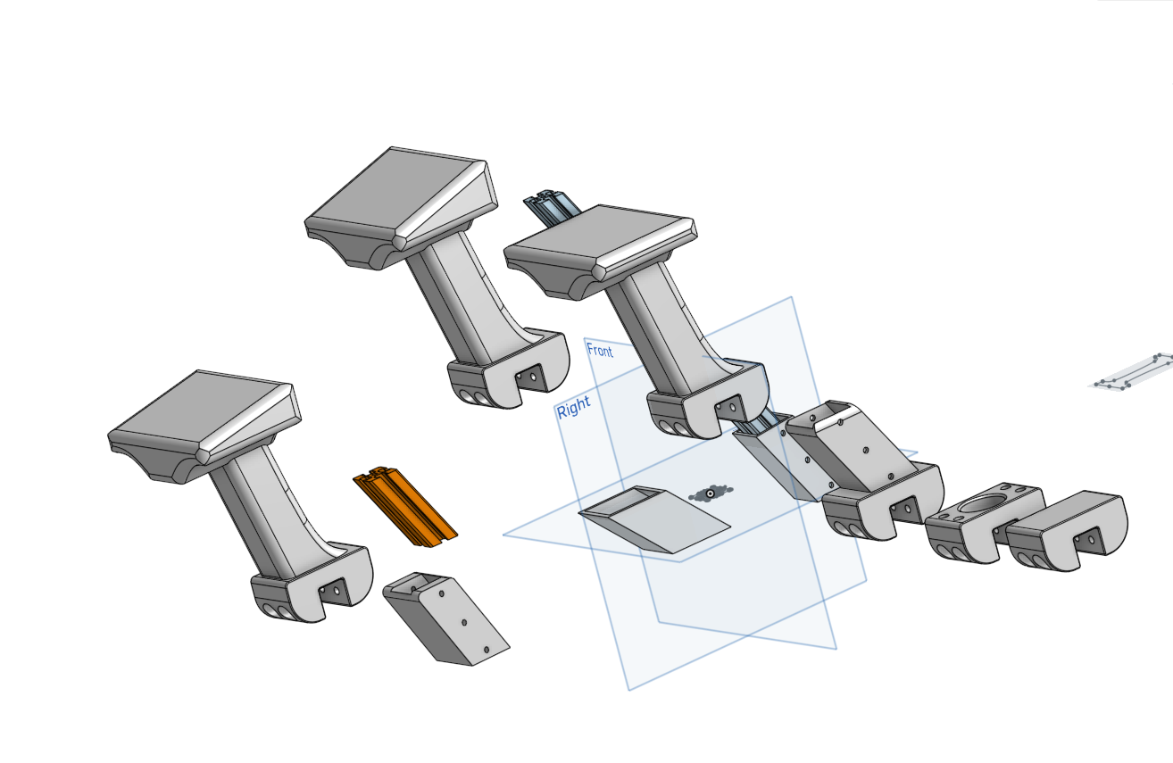
Let's walk through a couple things in this image so you can get an idea of some of my plots and plans for when I can get back to working on Tenacity.
First we have these "sensor stalks". The one with the flat top is what's currently mounted on the rover. I'm playing with different angles on the top to incline a camera or LIDAR and give it a better view of the obstacles in front of it vs. seeing things at knee height and missing things underfoot. The one off to the left in the back is inclined 15 degrees. The one in the front is tilted 10 degrees.

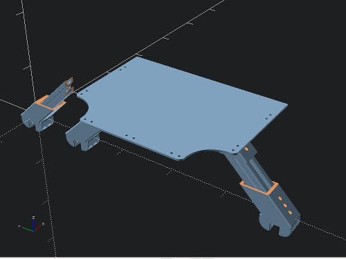
As much as I've tried to keep the cable plant under control with twisting and flex-wrapping the cable bundles, velcro-ing and routing them along the corners, it's becoming obvious that I'm going to need to add an additional "equipment deck" above the top of the body box. The original impetus behind this was to have a place to mount a Jetson TX1, but the more I worked out what the compute and vision-processing system would look like, the more I realized I just plain needed more space.
So here's a quick sketch of what that might look, modeled in a mix of OnShape and OpenSCAD.


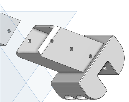
The bracket is slotted for a length of 1515 to be inserted to support the weight of the additional hardware mounted up top.
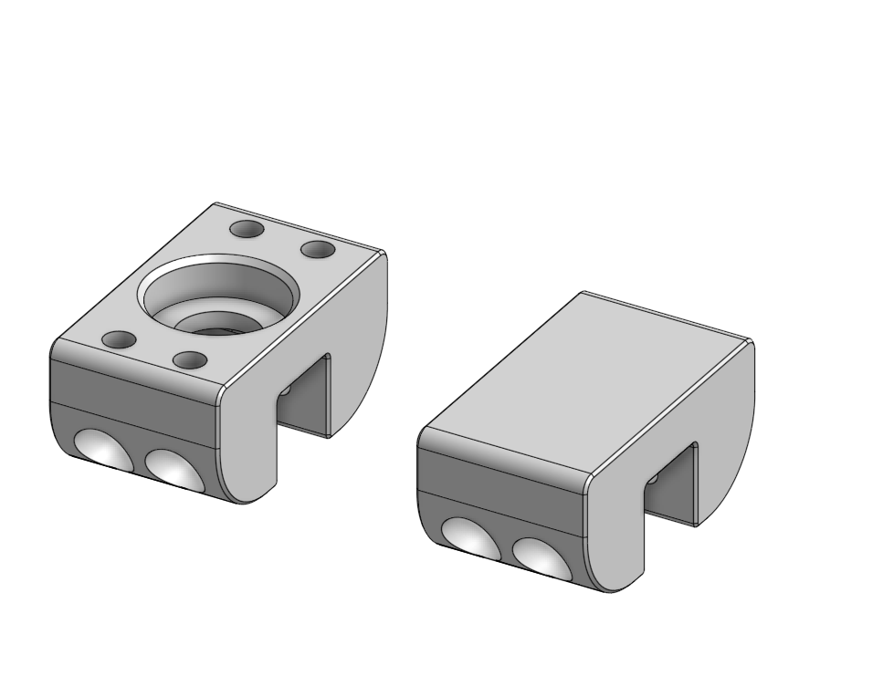
Finally, we come to this bracket here, which has been showing up in most of the images here and should be recognizable by most Sawppy Builders as the bottom part of the differential holder. When I was building my Sawppy last summer, I became rather captivated and inspired by this particular piece. I really liked how it fit into the upper part of the differential and how it clamped onto the crossbar. So I "repaired" the holes in Onshape to make it a universal mounting bracket.
I'll upload these to my GitHub fork of Roger's Sawppy repo in case anybody finds them useful.

 Steve
Steve
Discussions
Become a Hackaday.io Member
Create an account to leave a comment. Already have an account? Log In.
Hi - I wanted to ask you if you had gotten through the same thing I am noticing here on the original design, because I ended up designing my own brackets!
I was putting my rover together last week and when I got to putting this particular bracket onto the Diff bar I noticed that:
1. It is one of two parts that the barring fit in it loosely, why is the hole diameter 1.5 mm larger than that of the baring? And the piece that sits on top of it has the same problem!
2. The joint that sits inside both of them has two knobs that are smaller in diameter than the Inner Diameter of the two Barings!
With those 3 parts everything sits loosely inside one another. All else on the rover design so far is on point. How did you resolve this?
Are you sure? yes | no
Hi Ameer,
Thanks for stopping by to say hi!
I talked to Roger about this last year when I was first printing and assembling "Tenacity" and ran into similar problems.
He said that he dimensioned the holes for various parts to work with the tolerances on his 3D-printer, which could vary with the printers others use.
What I did was to "fill in" the holes on the parts I had problems with(The Diff Bar bearing parts, the steering knuckles, wheel and motor hubs, etc) in OnShape or OpenSCAD and then print those. I placed a cube or cylinder inside the problematic hole to fill it in, then used a Boolean difference() operation to cut new holes to size.
I really should go post those files to my Github so others can get at them. I can't remember if I did or not.
Hope that helps you!
Are you sure? yes | no
It's great to see the differential holder design adapted to other uses, especially those that share common need to have a strong and rigid connection to extrusion beams. Your camera and LIDAR platform fits that criteria well.
And just to add another tool to the toolbox: I've also designed a claw that clips on to 15mm extrusion beams. This concept is useful for places where rigidity is less of a concern and/or tool-free easy removal is useful, which was the case when mounting a wireless router to my Sawppy's rear beam.
https://newscrewdriver.com/2019/05/21/mounting-bracket-for-sawppy-wireless-router/ (The "rigid" in this post is relative, of course...)
https://cad.onshape.com/documents/43678ef564a43281c83e1aef/w/392bbf8745395bc24367a35c/e/f19959c4d5a4ae94b731f7d7
Are you sure? yes | no
Hey Roger,
Thanks for the link to the router part. I'm glad you liked the mods I've made to Sawppy so far.
I like the "claw" concept as the insert method is great for first assembling Sawppy, but for mods and enhancements, you pretty much have to take big parts of the frame apart to add more inserts.
I've also been looking at an "airless tire" mod for more outdoor use. I'll let you know how that goes.
Are you sure? yes | no