Supercell
-
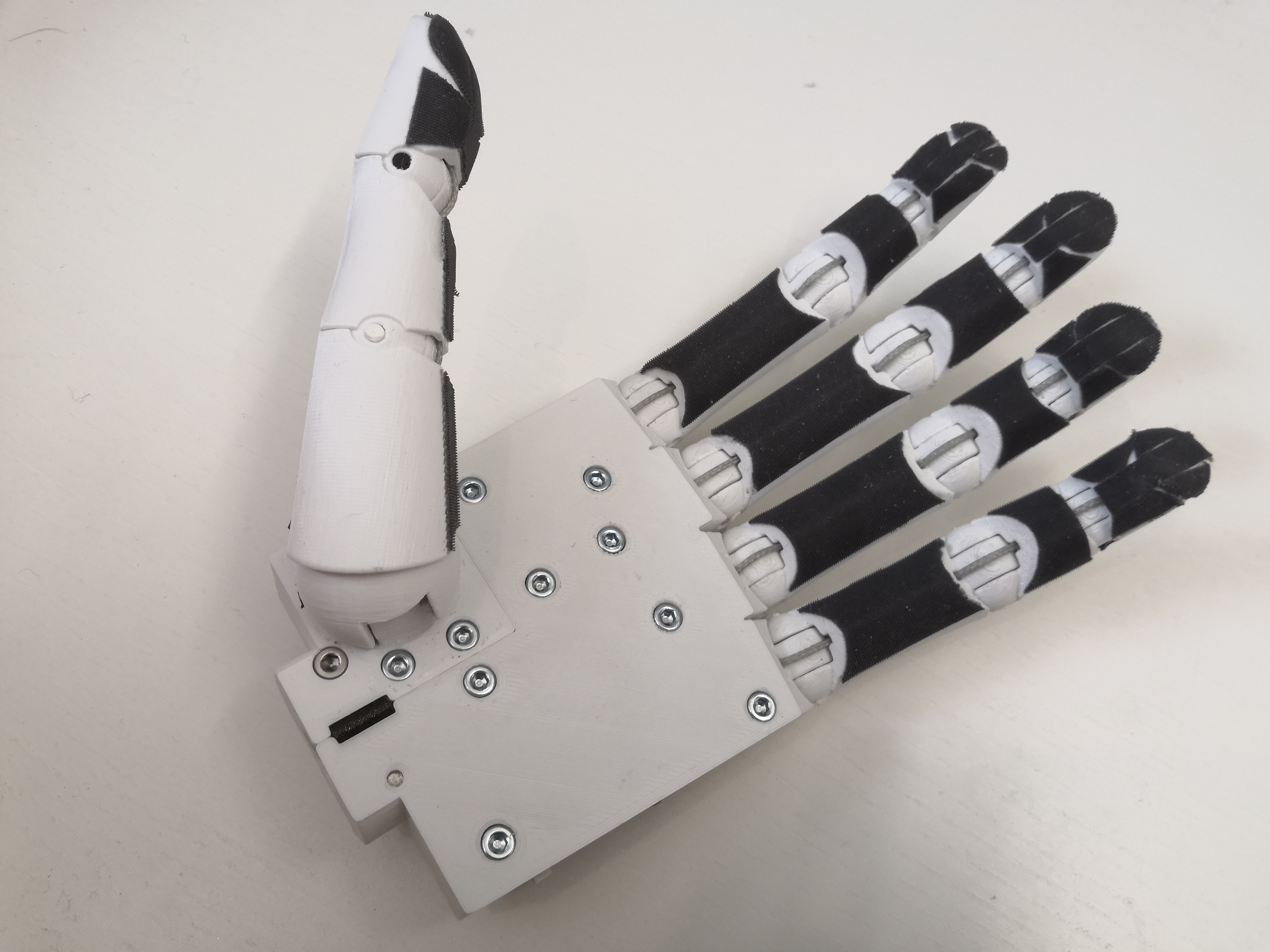
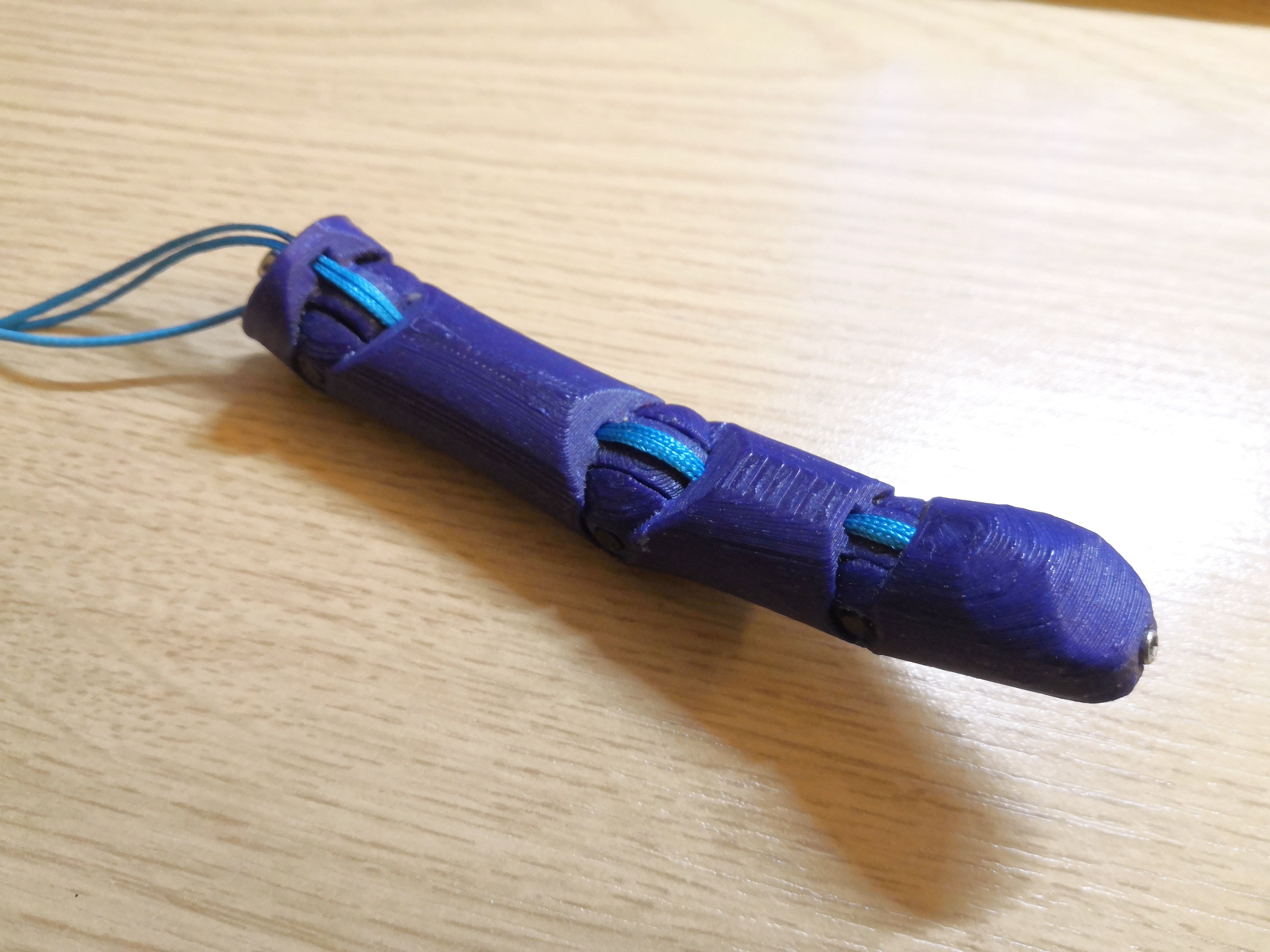
MK0 Hand Prototype
11/17/2019 at 14:36 • 0 comments4 Sept 2019
First design commitment based off of the 3 individual sub prototypes for each finger. The design brings together the each section into a single shell to make efficient use of space for an extremely compact design.
Reliability of the hand fares a lot better than the other hands that were designed quickly. Certain parts in this design are designed to be replaceable, such as some of the motor components and finger modules with detachable cords. The replaceable finger modules also allows for easy change of fingers to suit different requirements, such as when holding a pencil for long periods or for fix/sprung fingers for user preference/requirement.
The performance of the hand works fairly well with the motors used. The motors provide a good amount of torque, and is able hold onto items with a firm grip. The fingers do still require some form of gripping material so the smooth plastic fingers drastically reduces its capabilities in holding items.
The hand still maintains a fairly easy to print and assemble design whilst being low cost. The overall materials cost is around $40, which makes it fairly affordable for anyone to create, however, the most difficult part to source for this design is the main PCB which handles the motors. Whilst there are some cheap PCB fabrication services online, the main issue comes with the assembly of the PCB which really puts up the price if only doing a one off. It's not an issue for some who's experienced in soldering small ICs to assemble PCBs, but most won't be able to. For now, I would only recommend those who have experience in soldering to attempt the design if they're interested.
[Additional documentation to be added]
Features:
- Small size
- 4 motor design
- Reasonably good closing strength (firm grip when shaking hands)
- Replaceable/swap-able motor parts and finger modules
- Sprung tips
- Low cost at around $40 in materials (not including batteries)
- Light weight at less than 200g (not including batteries)Further work:
- Improve ease of assembly
- Add method of wrist attachment
- Additional finger modules
- General design improvements for hand -
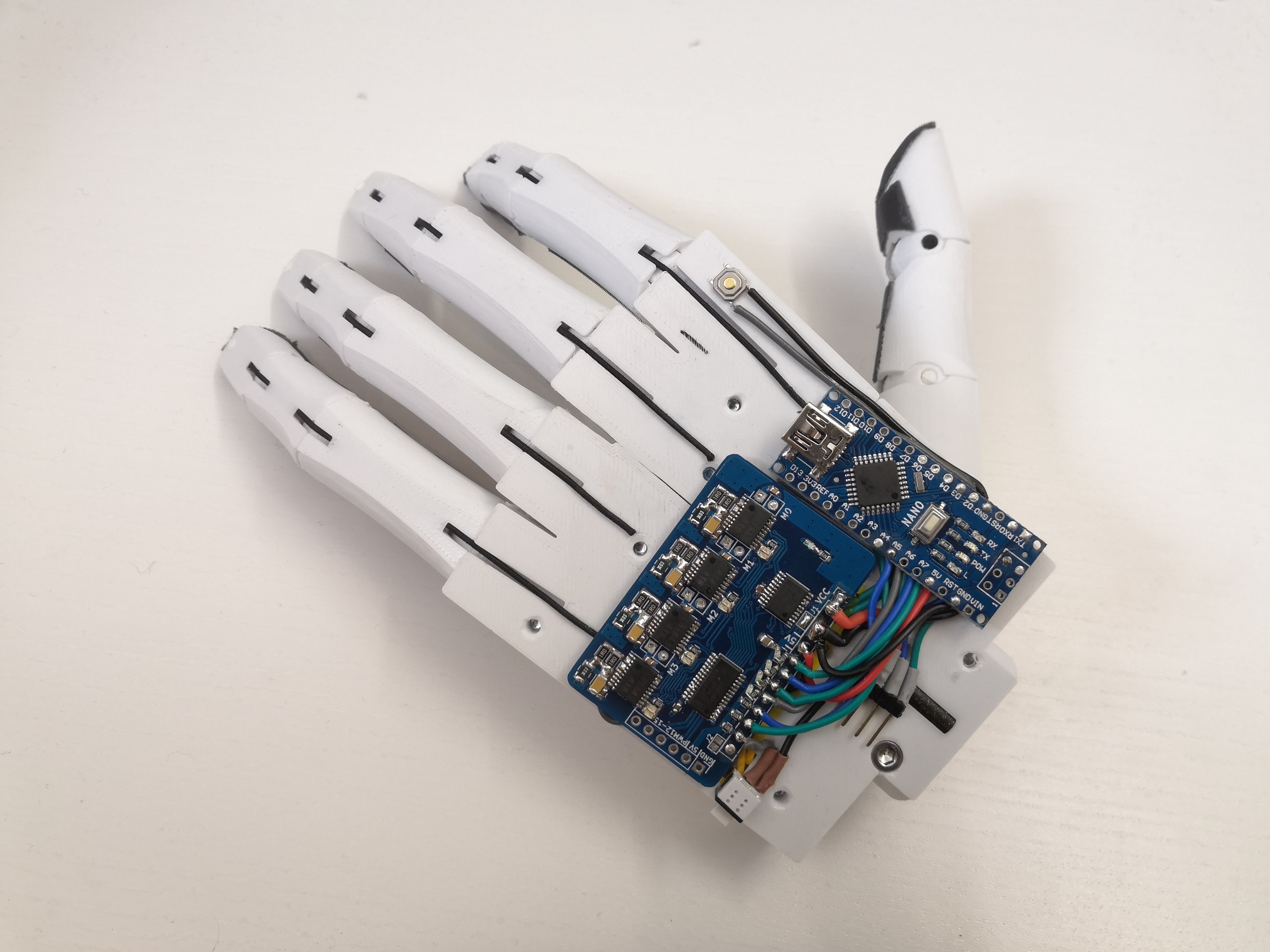
V1 hand prototype
11/17/2019 at 14:36 • 0 comments15 May 2019
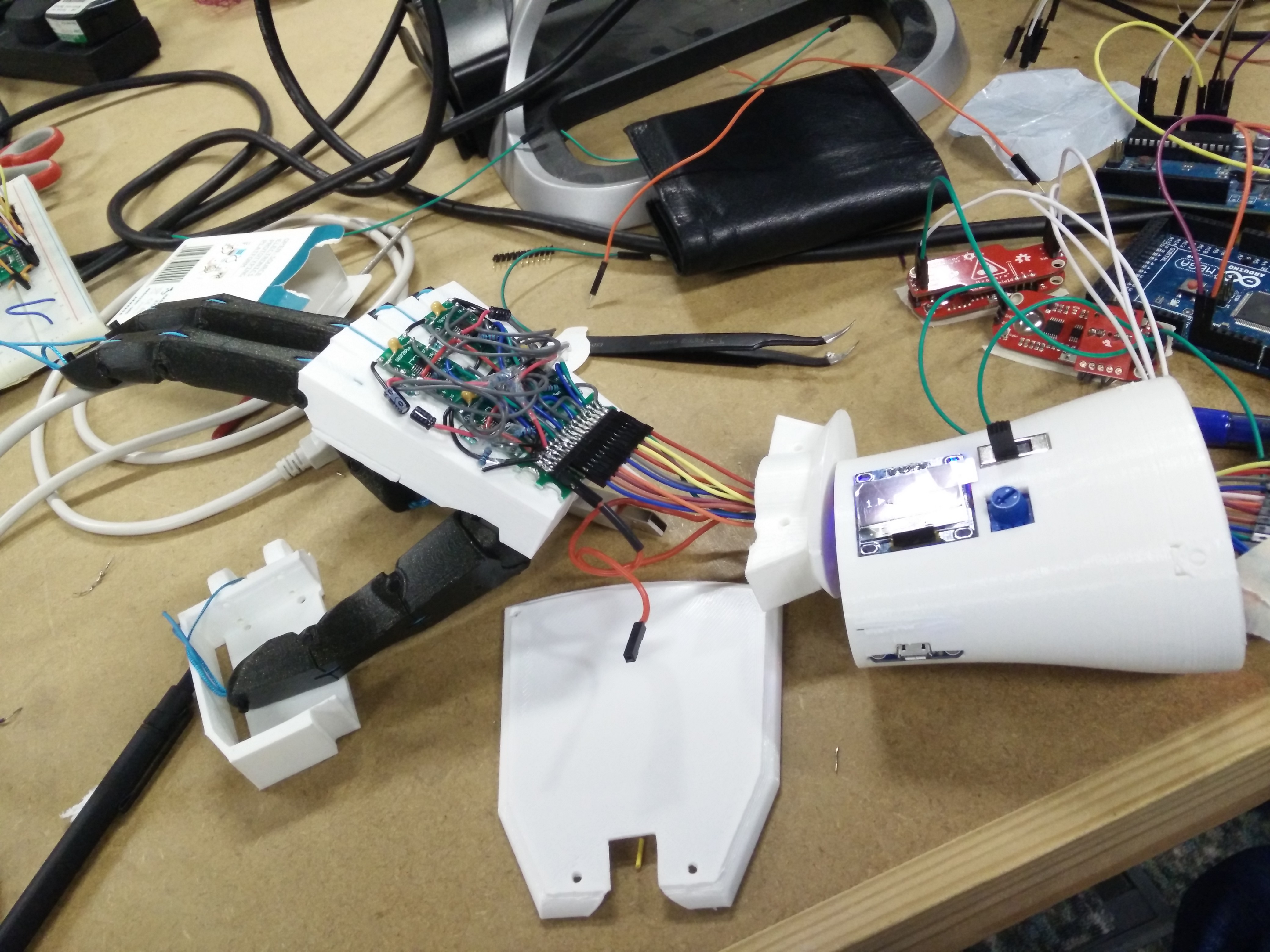
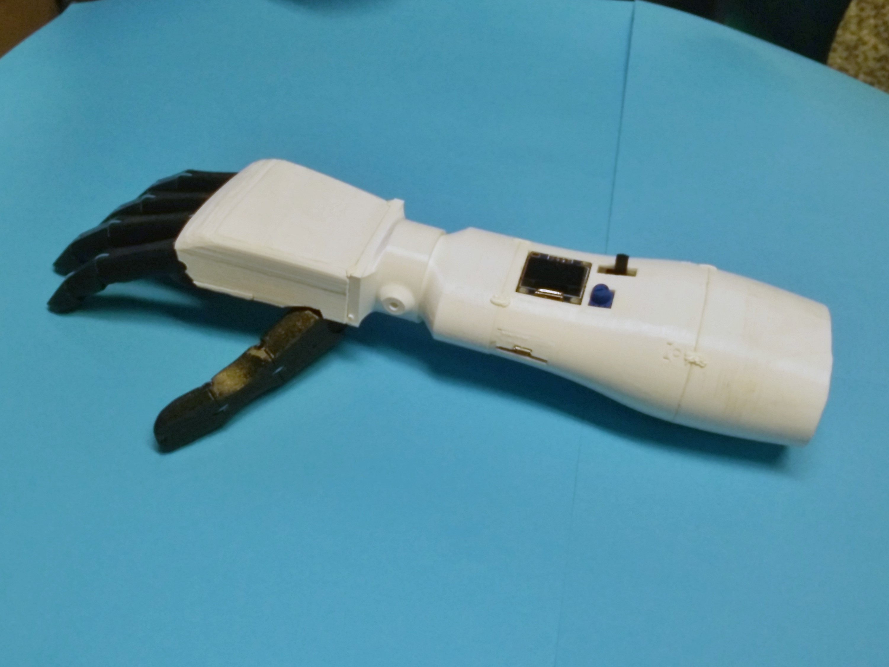
This prototype iteration uses slightly more expensive motors along with the I2C PCB, and was used by Augment Bionics. Concept of the design is still the same but with slight improvements in CAD design. The designing of the hand took me about a month and the final assembly of the entire hand, circuit and UI was made within a few days. V1 faired considerably better than V0, however, still required maintainace as parts would fail. This was due to some aspects of my design which I wanted to fix before making V1 but hadn't quite figured out a solution at the time.
[Additional documentation to be added]
Credits to:
George Dzavaryan
- Designing and printing the forearm socket and UI housing, and helping to print out the V1 hand.Alex Roy
- Creating the software for V1 that manages the separate Arduinos for the V1 hand, UI and MyoMoritz Müller
- The presentation of V1Augment Bionics Members
- Helping with some of the assembly and design of UI system and software for forearm socket.![]()
![]()
-
Trial test of a hand
11/17/2019 at 14:14 • 0 comments1 Apr 2019
This prototype hand mainly consists of individual component testing of different aspects of a hand. The sections are split into three unique models that differ in their roles.
- Green section
Focuses on the testing of having a single motor per finger for index and middle fingers. Motors have been re-orientated to reduce the form factor taken up from the previous two finger design. - Orange section
Focuses on distributing a single motor actuation across two finger for ring and pinky. This section is designed differently to have a slightly more closer design to a human hand with smaller ring and pinky fingers, along with a slight angle to the palm. Actuation system also tests a different pulley design to split load between ring and pinky for better conforming grip between fingers. - Blue section
Focuses on single motor actuation of the ratcheting thumb to check for issues in routing of the cord as well as positioning of the motor.
The three section have common design attributes with motor choice and operation. They all test a new rubber end stop design which hopefully reduces the sudden stop that result from the motor reaching the end of rotation.
[Additional info to be added]
- Green section
-
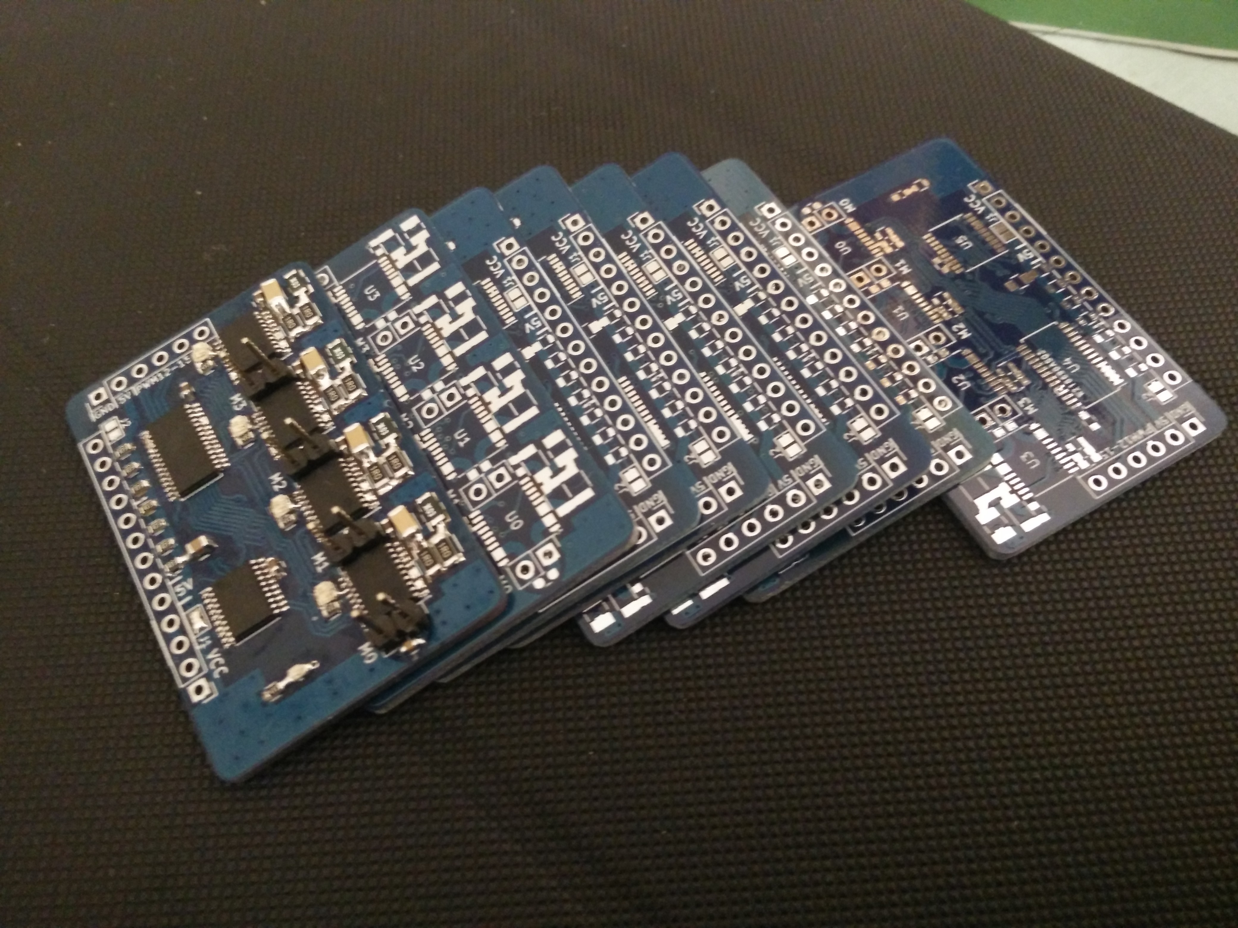
V2 PCB prototype
11/17/2019 at 14:00 • 0 comments07 Feb 2019
PCB design made using a different motor driver IC. The new IC used has a significantly smaller footprint along with lower overall PCB cost. Capabilities of the IC are similar to the old ICs but with less control features that are outweighed by the improvement of smaller footprint and lower cost.
Features:
- Smaller PCB
- Lower component cost
- ATmega328P microcontroller
- All microcontroller pins broken outSpecs:
- ATmega328P microcontroller
- 5V operating voltage for drivers and microcontroller
- I2C motor drivers
- D9, D8, D5 and D4 are used for the limit of M0 to M3 motor drivers
- D13 LEDFurther Work:
- General PCB design improvements for hand, e.g. better layout, more features, etc.
KiCAD: https://kicad-pcb.org/
-
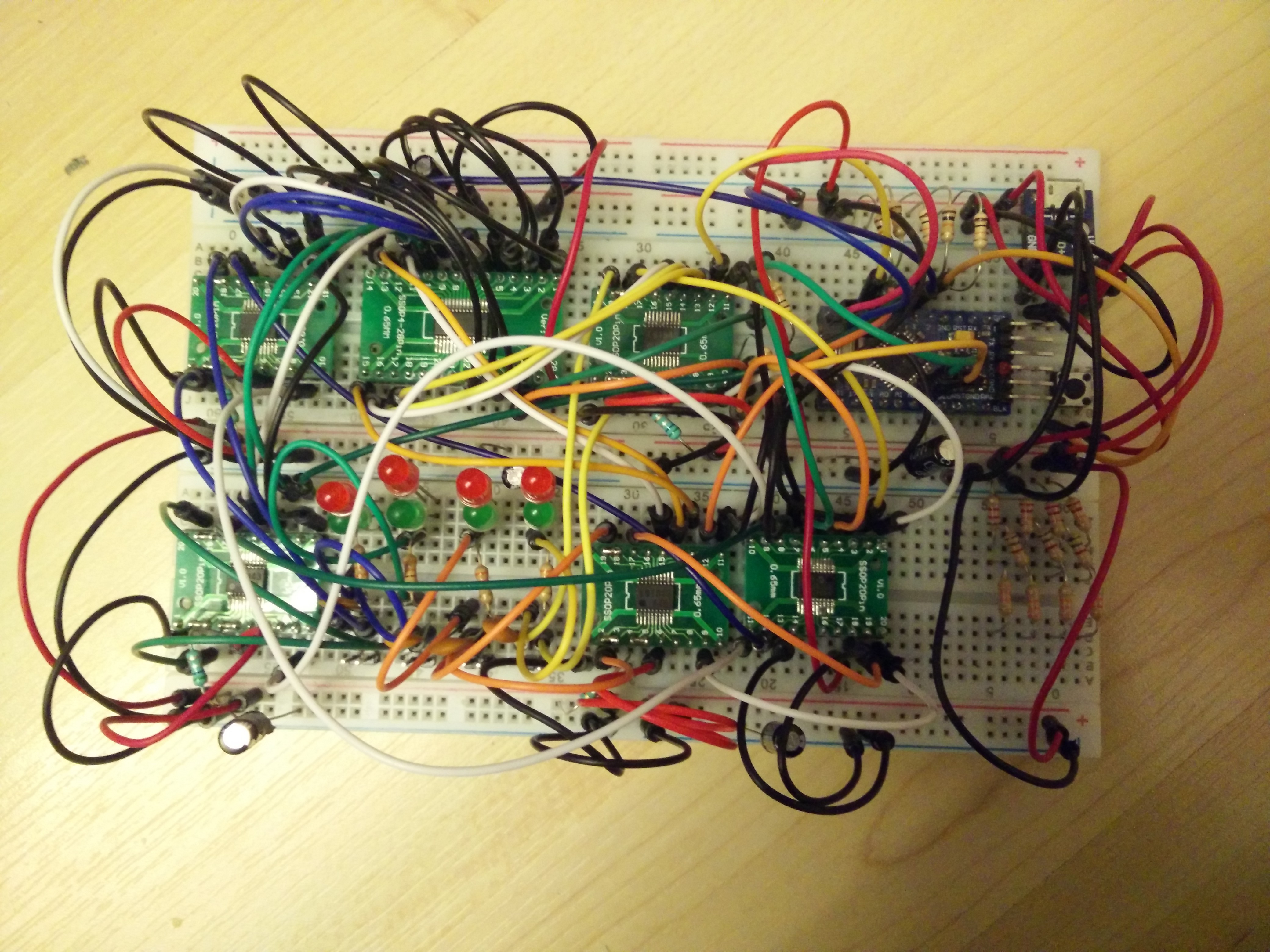
V1 PCB prototype
11/17/2019 at 13:49 • 0 comments11 Jan 2019
Two versions of the circuit were created and tested:
- Version 020 which used shift registers for controling the drivers along with a 4 bit R-2R DAC
- Version 010 which used the PCA9685 with a digital potentiometer to control the drivers
Both versions worked well with different benefits. First version was cheaper and the second offered more control via I2C for slight increase in cost.
Eventually, I had decided on using the I2C version for testing and development.
![]()


![]()
KiCAD: https://kicad-pcb.org/
-
V0 hand prototype
11/17/2019 at 13:46 • 0 comments05 Nov 2018
The V0 hand prototype was one of the first hand prototype that I had designed. The entire CAD design, printing and circuit wiring was done by myself over a few nights due to my reluctance of moving from a 2 finger prototype to a full hand prototype. Many elements of the design were not fully tested, and as a result, this prototype wasn't too successful in terms of a reliable and functioning hand. Parts of the hand failed easily, from the bird nest of wiring to the failure of parts in the hand. Overall, the prototype was successful enough to be presented, but didn't last very long afterwards.
Credits to:
George Dzavaryan
- Creating the CAD and parts for the forearm assembly with UI, and had helped try to make an attempt at a hand design to house the motorsAlex Roy
- Creating the software for V0Moritz Müller
- Helping with assembly, testing and demonstration of V0 with the forearm UI
- Making development log on V0 for Augment Bionics TeamAugment Bionics members
- Designing of the forearm UI![]()
![]()
-
MK0 Hand Prototype
11/17/2019 at 13:44 • 0 comments10 Sept 2018
Motorised dual finger prototype changes from a screw driven actuator to a winding actuator for experimentation. Design uses the same drivers and motor style from previous design but with different performance characteristics. Using a winding system, the fingers offers greater gripping and lifting strength, but at the cost of degraded holding strength. In different use case scenarios, greater gripping strength may be more beneficial in one case, and greater holding strength in another case. As performance requirements vary from different scenarios, it would be difficult to have an ideal solution. For the case of the style of motors used, an ideal solution would be to have a good balance between gripping and holding strength. Another factor to consider is the overall space the motors take up for a given performance. Using a screw system along with long actuation lengths results in a large motor form factor which greatly takes up the limited space in the hand. As such, a winding system would be beneficial in saving space. To create a balance between gripping and holding strength for a winding system, a worm based motor with according pitch could be used, however, there's lack of small sized worm motors available for a low cost.
Features
- Similar features to previous design
- High gripping strength
- Smaller form factorSpecs
- Winding based actuation
- Same motor driver designFurther Work
- Better end stop design
- General design improvements, e.g. better reliability, smaller size, etc. -
Motorised V3 Finger
11/17/2019 at 13:43 • 0 comments16 Mar 2018
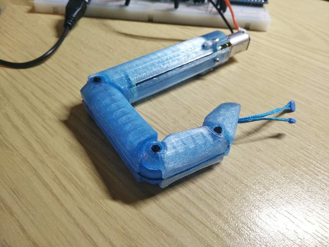
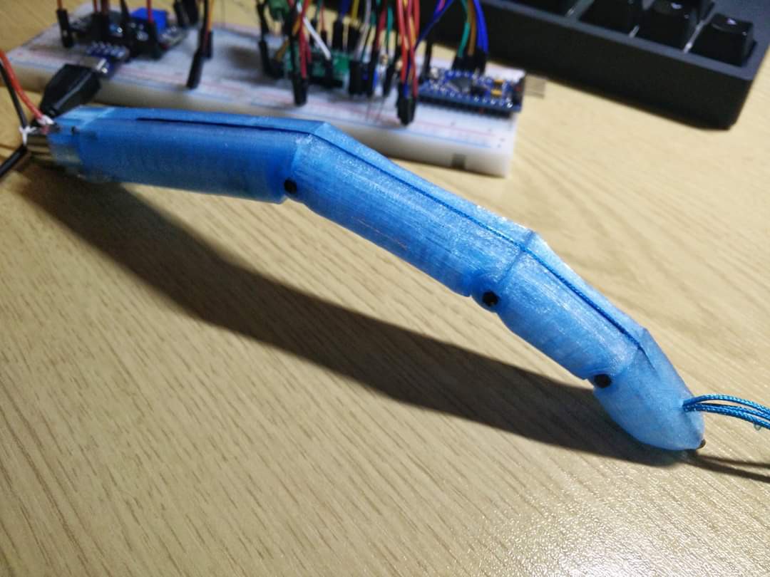
"New finger design~
This version uses a different pulley system compared to the previous that's more commonly used in other prosthetic hands. Changes have also been made to the choice of motor as well as the aesthetics of the finger.Improvements in design:
- Simplified assembly with the use of a single actuation cord.
- Increased load bearing capabilities. The finger should be able to hold more than 1kg with no power draw due to locking actuator.
- Reduced power consumption to less than 100mA at 5V during actuation (including boost converter running the motor at 7.2V.
- Increased actuation speed.
- Improved asthetics to match more closely to a human finger.
- The motor can be ran straight off of a 2 cell li-ion battery pack (7.2V - 8.4V) without the need of a high power converter circuit.
- The driver is now more compatible with the power requirements of the motor.
- Still has a non rigid finger when forced closed to prevent damage to the mechanism.
- The different pulley system allows for the finger to dynamically conform around any given object.
- Still low cost.
- Still 3D printed.Downsides of the design:
- The choice of motor stalls quite a lot easier than previous motor, so the gripping force is a bit weaker but still usable.
- The required actuation length has increased to 25mm which will limit how small the actuator can be.
- Has a lot of sliding friction so lubrication is a must.Changes to be made:
- Reduce actuator length
- Improve release mechanism for non rigid motion.
- Improve Arduino code.
- Make changes to design files for reliability and consistency when 3D printing.
- May make changes to mechanism to reduce actuation length.
- Ball bearings may be added to improve reliability.
- Figure out a way to add rubber grip.The design is still far from a perfect solution and isn't the best design, however, it certainly offers a low cost, low power and high load bearing prosthetic but with the downside of having a weak gripping force."
Jason Lee
![]()
![]()
-
V3 finger design
11/17/2019 at 13:37 • 0 comments4 Mar 2018
A third finger design iteration, made to look more aesthetically like a fictional humanoid finger. The design is based off of a ball jointed style of design for each joint, but using a hinged based system. Design has also been optimised for 3D printing, using the least amount of support possible whilst maintaining strength and aesthetic. The finger has similar benefits of previous designs but with the change of a single cord path to actuate the finger. The use of a single cord is fairly common within 3D printed prosthetic cord actuated designs, however, whilst it does allow for under actuation of each joint, it introduces uncertainty into the position and precision of the finger. In comparison to the previous V1 finger design, V1 cord path allows for predictable and fixed angles when actuation, but at the cost of difficult assembly and issues with increase cord segments and attachments.
Features:
- Improved aesthetics
- Maintained printability
- Low support requirements
- Extremely durable design with low wear and high load bearing joints
- Basic material requirements, nylon string, elastic cord and nylon filament
- Tested in PLA and ABSSpecs:
- 25mm cord actuation
- 3 joint finger
- Print supports required only on the underside of the hinges
- Nylon hingesFurther Work:
- Better cord attachment method
- Method of improving precision
- Reduce exposed cords to reduce wear from use
- Use of better elastic, spring or other methods for opening actuation
- Possible changes to joint quantity for adapting to different design requirements
- General finger design improvements, e.g. better printability, improved assembly, etc.![]()
-
First motorised finger
11/17/2019 at 13:27 • 0 comments14 Feb 2018
"Success!! Finally managed to get an electrical current based force detection using the cheapest of parts. Wasn't quite sure if it would work out together so didn't say anything about but it's now working pretty good. The design is only just a proof of concept and there are many things with the design that still need changing so it may not be the perfect solution to fit the task.
Pros of the design:
- Extremely cheap to produce with less than £8 worth of parts for the motor, driver and 3D printed parts.
- The finger moves freely when forced closed or has bumped into something to prevent damage to the mechanism.
- Current based feedback allows for the controller to calibrate the motor and to diagnose any issues the motor may have from long term use or damage.
- Grip strength can be fixed or adjust through the controller between a soft to a semi firm grip.
- Low cost for repair if the motor fails.
- Entirely 3D printed except for the screws, motor and strings.
- With a more intelligent current detection, the force sensing can be highly reliable.Cons of design:
- The motor is loud. Could be reduced with some rubber dampening.
- Actuation speed is a bit slow but the motor can be driven at a slightly higher voltage or a different motor could be sourced.
- Actuator length is a bit long but can be shortened by 3cm.
- Power draw from the motor during actuation is a bit high at around 0.1-0.2A at 5V mainly due to the motor having to work against the elastic cord. A few design changes to the mechanism could help to reduce it.
- The driver that is currently used barely fits the requirements of the motor and the application it is used. Another driver may be sourced or design changes to the mechanism and software could be done to work around it.
- No speed control at the moment but may be able to be implemented using the current limit of the driver."Jason Lee
ARX Hand Project X1
An advanced low cost 3D printable robotic hand for development in robotics, animatronics and prosthetics