0%
0%
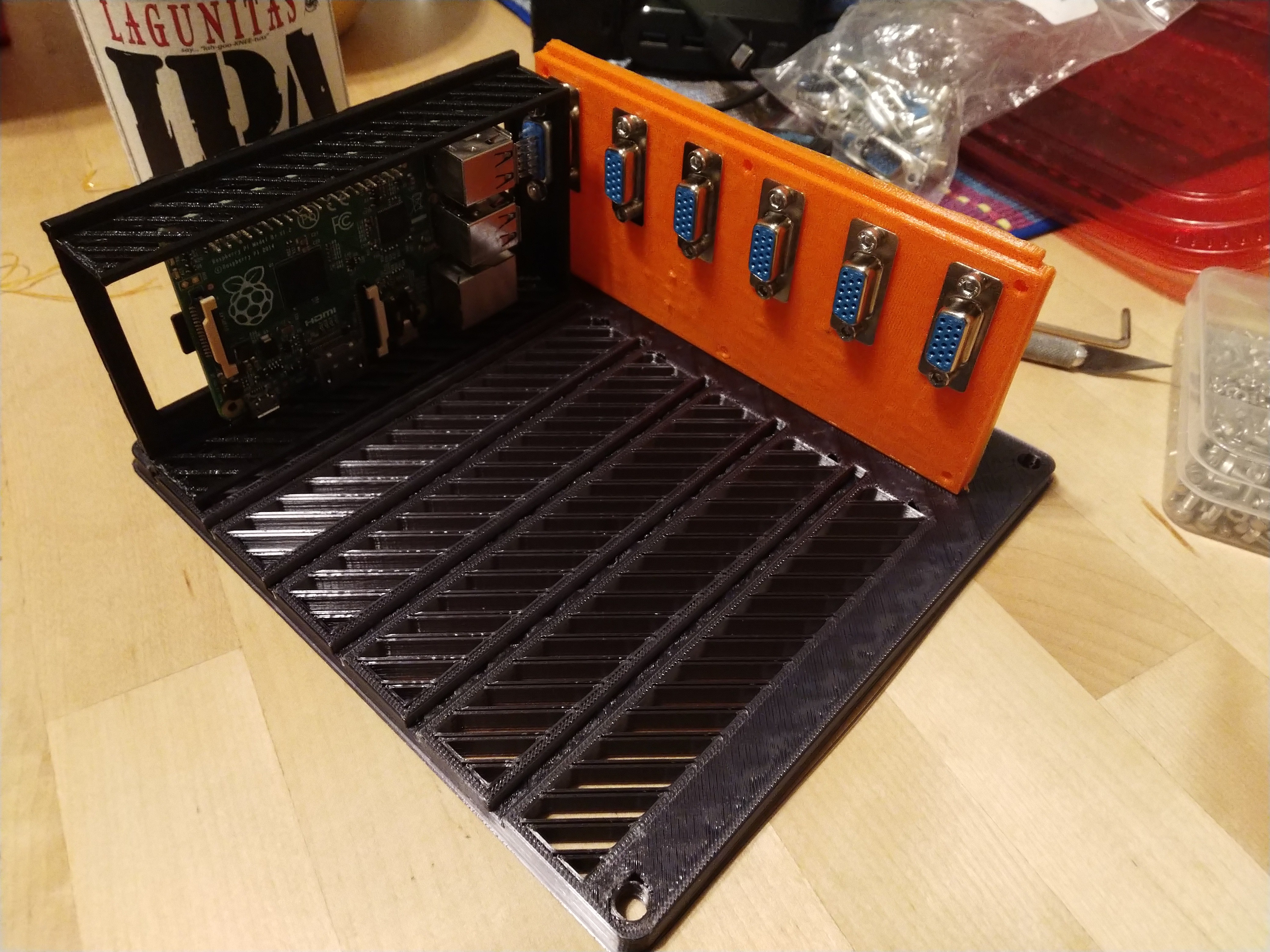
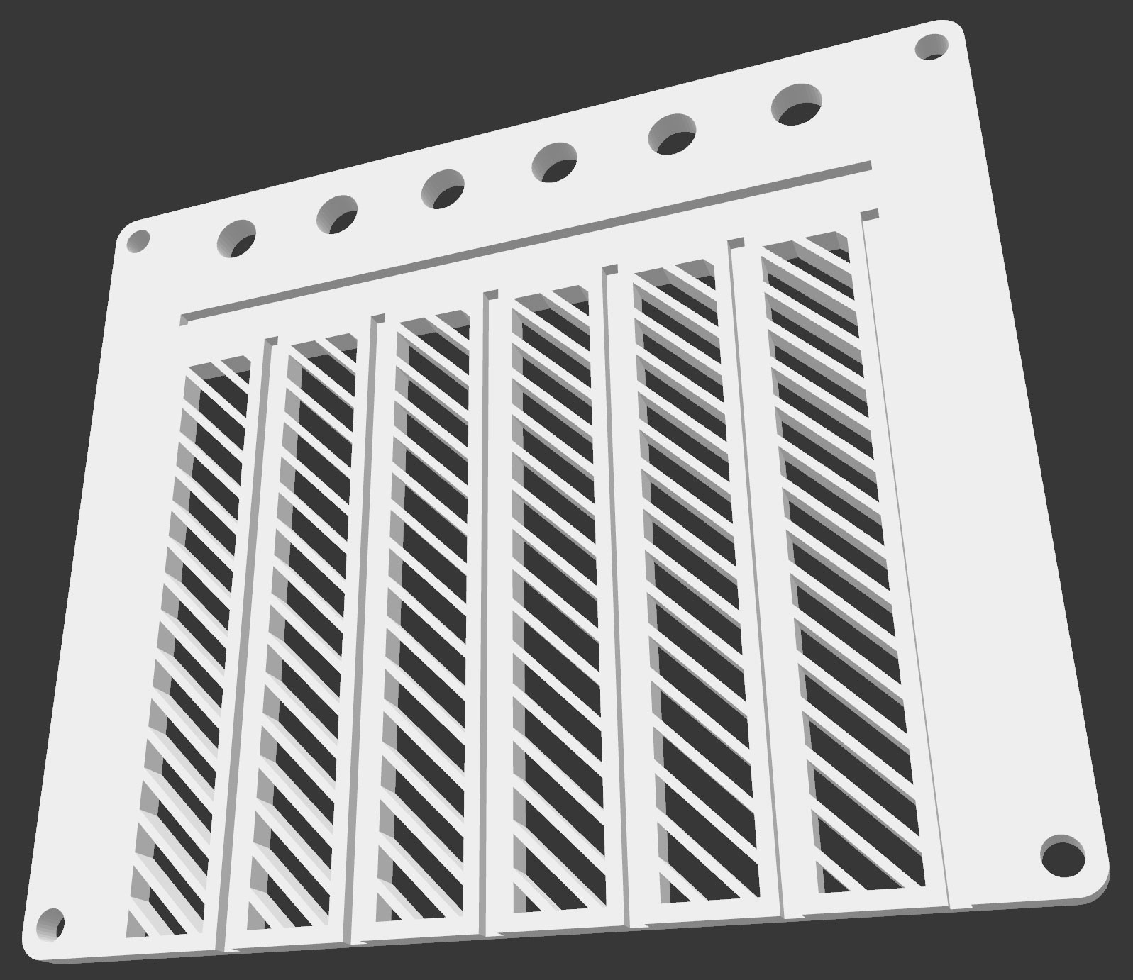
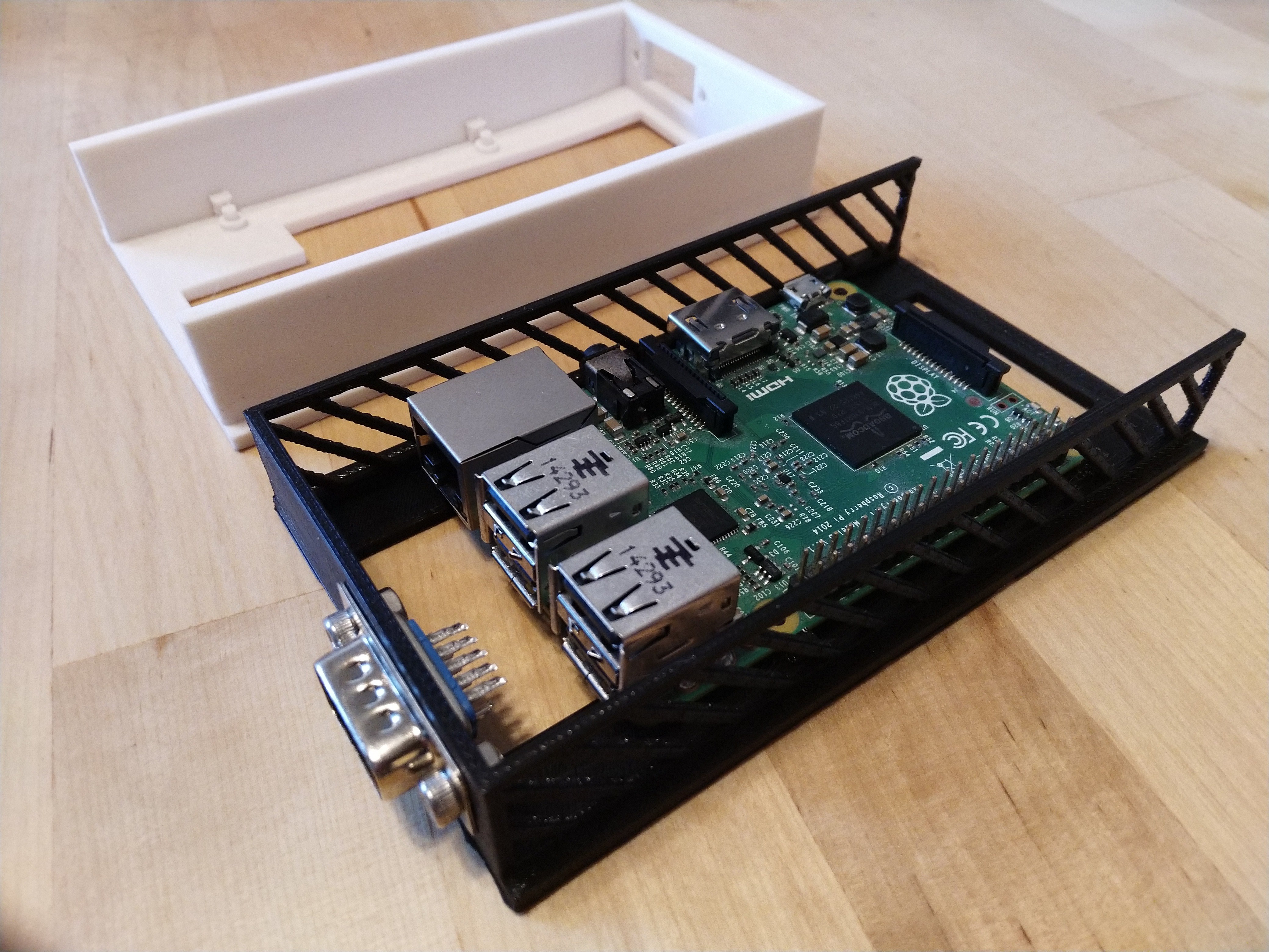
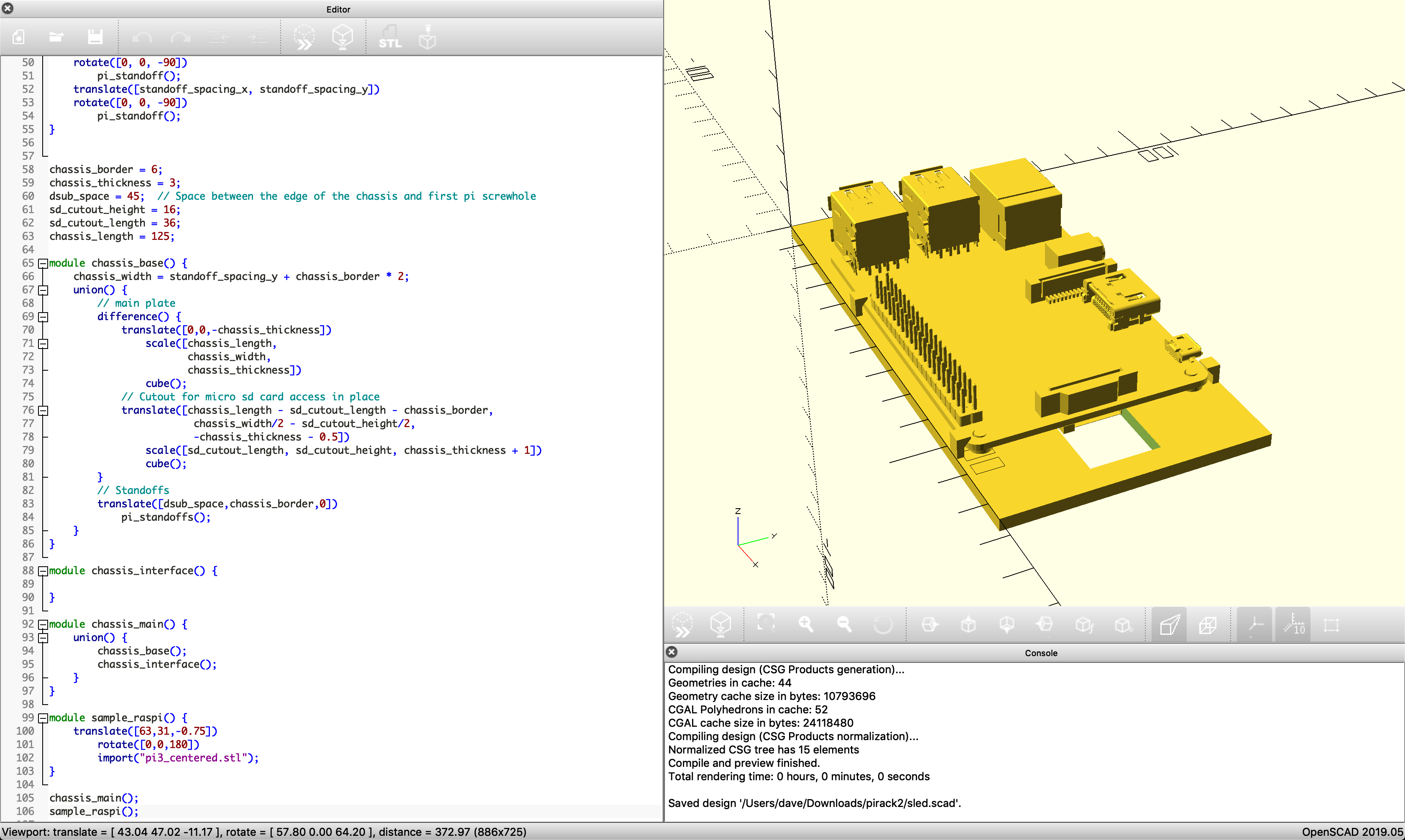
Raspberry Pi Rack for the Pi 4
A 3d printed enclosure to house multiple Pis, updated for the Raspberry Pi 4
 Dave Pedu
Become a Hackaday.io member
Already have an account? Log in.
Just one more thing
To make the experience fit your profile, pick a username and tell us what interests you.
Pick an awesome username
hackaday.io/
Your profile's URL: hackaday.io/username. Max 25 alphanumeric characters.
Pick a few interests
Projects that share your interests
People that share your interests

 Jorge Miar
 Ryan Walmsley
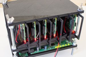
 Jdaie
Jdaie