 UTSOURCE
Schematic Diagram
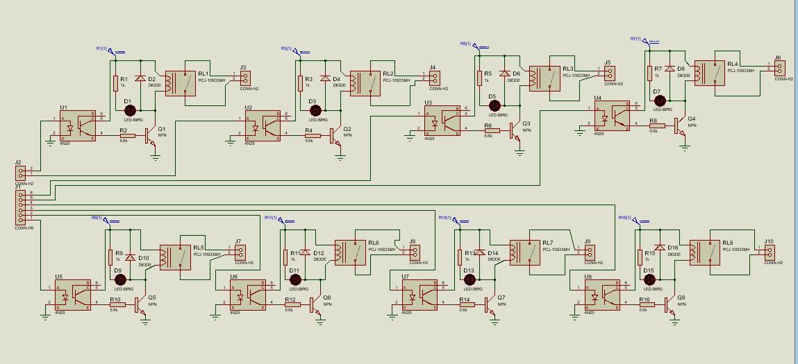
Schematic diagram of the 8-channel relay device is shown above in the diagram. It consists of 8-channel relays connected with the 8- headers through the Optocoupler device which provides the isolation between the circuit to project it from high voltage.
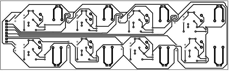
PCB of the Circuit
Below is the PDF of the PCB design of the above circuit to implement it on the circuit board.
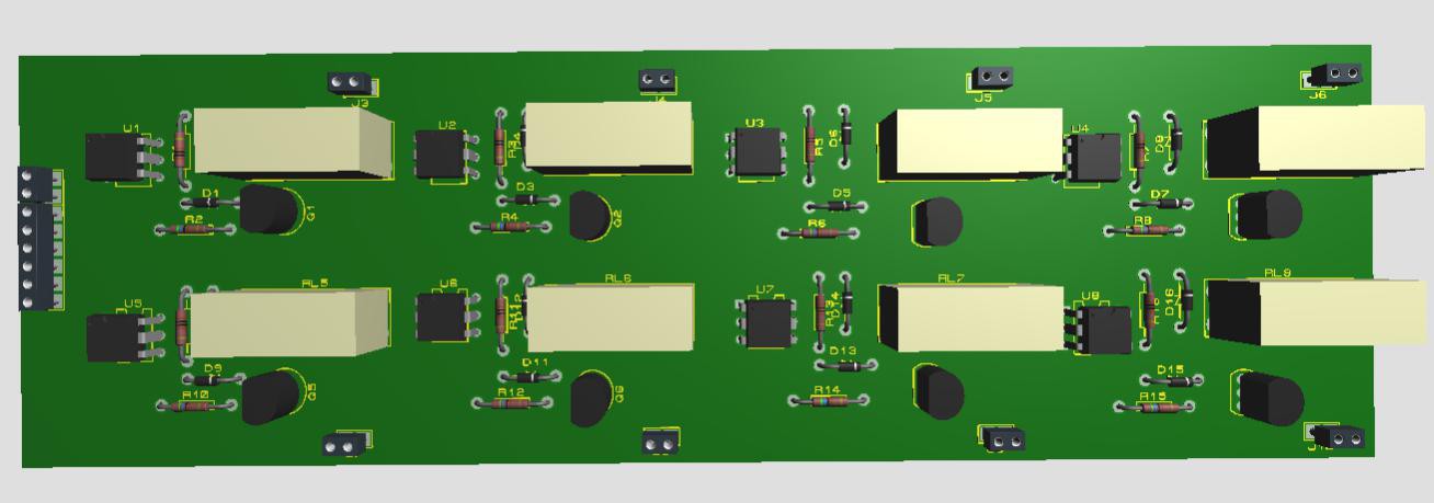
3-D Model
Below is the 3-D Model Just for Understanding of the circuit.
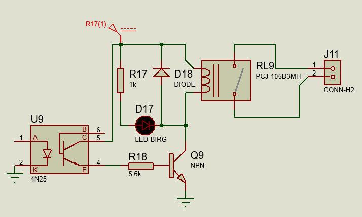
Circuit of Relay Device
Here is the circuit diagram of the 1-channel relay just for understanding of the above complex whole circuit.
Component lists
Relay | PCJ-105D2M-WG,000 8pcs |
Optocoupler | 4N25 8pcs |
2N5172 PBFREE 8pcs | |
LED | QBLP653-R 8pcs |
Header(2-pins) | SMS2RE3TR29 8pcs |
Header(8-pins) | PPTC081LFBN-RC 1pcs |
Resistor (1K) | FMP100JR-52-1K 8pcs |
Resistor(5.6K) | PR01000105601JR500 8pcs |
Diode | 1N4007-TP 8pcs |
Features of the Circuit
- This system relay support control up to the 250VAC, 30VDC and 5A switching current.
- This relay has the coil voltage of the 40mA. Any current above this current will damage the relay.
- Optocoupler is used to isolate the circuit to avoid our circuit from damage.
- You can program the 8-pin header of the circuit to control it through the microcontroller like Arduino, Raspberry pi, etc.
- Simulation and the PCB Designing of the circuit is done on the Software of Proteus.
Explanation
Relay
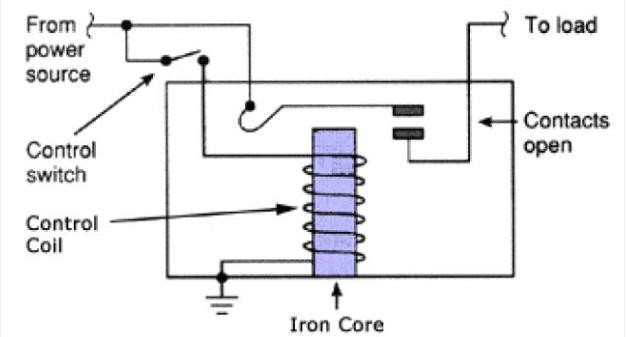
Relay is a switching device which is used in for automatic switching if the fault current or the voltage is passed beyond the limit of the relay ratings of voltage and current. They basically are used to separate the rest of the circuit if fault voltage or current is passed above the rated voltage and current in order to keep the system (fans, bulbs and other device) save.
Relays basically have the low driving current which is also called the coil current of the relay. And through that current they control the high voltage and current which varies over a wide range from electronics to power electronics to high voltage transmission line but their basic working principal has some similarity. Below is the principle structure of the relay. In which as the current passes through the coil the relay is operational in the circuit and when the current or the voltage above the normal range contacts become closed and the current stops flowing in the outer circuit. Note that coil of the relay is always isolated with the contacts or the switching point of the relay.
Optocoupler
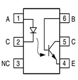
Optocoupler is the IC which is use to isolate the one part of the circuit from another just for the purpose of the safety.
In the Ouptocoupler circuit diagram we have the LED at the 1 and 2 terminal of the 4N25 which is used to trigger the base of the transistor to produce the same signal at the output terminals 5 and 4 which are the collector and the emitter of the 4N25. Signal is same but input is isolated from the input. Below is the internal structure of the IC 4N25.
Transistor
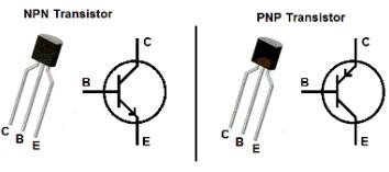
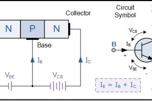
A transistor is an electronic semiconductor device which is used to amplify the input signal or it can be used as a switching device. In this project we use it as a switching device to trigger the coil of the relay.
Transistor is of two type like NPN and PNP but the most used configuration of the transistor is NPN. Below is the symbol and the picture of the both NPN and PNP transistor. In NPN transistor the arrow comes out of the Emitter while in PNP transistor arrow comes in to the collector.
 engineerkid1
 Ben Holmes
 Electroniclovers123