I could not find any data sheets on this specific model of display, but with some experimentation I figured out the H1 connector pins for the 25 columns and the H2 connector pins for the white and black row coils. The pixels of the display flip when given a short pulse of 9 volts at about 150mA. To set a pixel black, the black row input signal needs to be low while the column is pulsed high. To set a pixel white, the white row input signal needs to be high while the column is pulsed low. So pulses of both 'high' and 'low' are required, and the drivers for the display are ideally in a high impedance state when not driving a pixel. I found a perfect chipset to do this - the MIC5821 (eight sink drivers) and MIC5891 (eight source drivers). These chips allow interfacing to standard 5 volt logic and allow control of the 9 volts required to flip the pixels. The MIC5821 and MIC5891 utilize a serial shift-register driven design. The desired states of the outputs are shifted in and then the output enable is raised to assert the state on the output driver.
At the 9 volt level that I used, it takes approximately 36 milliseconds to flip a single pixel. Updating all 175 (7x25) pixels therefore takes over 6 seconds. To make the display update faster, the software remembers the current display state and takes into account which pixels actually need to be flipped and changes only those that require it so the clock updates much faster in practice.
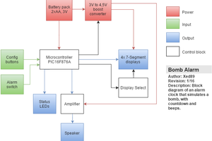
A PIC16F887 is used as the central processor, and a battery backed DS1307 real time clock provides timekeeping through power outages. I programmed the PIC using the Microchip MPASM assembly language IDE, but first drew out all the code as flowcharts. I decided later to add an MCP2200 USB-to-serial chip to allow a terminal program running on my windows tablet to control the time and mode setting functions of the clock. The USB cable does not need to be connected for normal operation, just when I want to change something or adjust the time a couple times a year.
The circuit is assembled on a PC board made using Eagle schematic editing software. I used press-n-peel blue transfer paper to put the circuit on a single sided copper clad board and then etched it using ferric chloride. My board is single sided, but there are a large number of jumpers on the top side of the board due to the complexity of the circuit. The MCP2200 USB chip is mounted on a small surface-mount to DIP adapter board that I made using the same technique, and the rest of the USB circuitry is just on a small piece of perfboard.
Modes for the clock include:
- Large 5x7 pixels hours:minutes
- Large 5x7 pixels minutes:seconds
- Small 3x5 pixels hours:minutes:seconds
- Small 3x5 pixels month-day-year
- Small 3x5 pixels day of the week and date
- Auto mode - switches between all the modes automatically
- All black - changes the display to all black
- All white - changes the display to all white
Additionally, two functions are available to tailor the display:
- Row/column invert - switches the display to update in row-major or column-major order
- Invert black/white - inverts all the pixels so the display can be black-on-white instead of white-on-black
Finally, there are a couple time management commands used with the serial terminal when it is connected:
- Read time - reads the time from the DS1307 chip and displays it to the serial terminal
- Set time - allows the serial terminal to enter time updates and store into the DS1307 chip
 Xed89
Xed89
 Ricardo Sappia
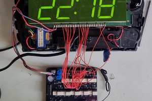
 zst123
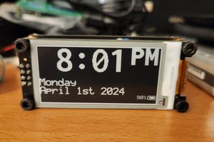
 sjm4306