Jeff Cooper
-
Why There Haven't Been Updates
11/19/2020 at 03:02 • 0 commentsI've been waiting patiently for the replacement display module to ship so that I could get working on the watch again. When I ordered the replacement(s) in September, the backorder ship date was November 13th. For those playing along at home, that was Friday of last week. I've put several requests in to Digikey asking why the parts haven't shipped; the impression I get is that the delivery from Flex hasn't come in yet. Hopefully I'll hear something soon. In the meantime, I'm just... waiting.
On the plus side, Sharp's website finally acknowledges the existence of the LS018B7DH02! It's listed as "new" (ignore the fact that I found reference to it in catalogs back to 2018) and still doesn't have a datasheet attached, nor does there seem to be any way to actually get one (I have an email out to my local supplier), but it's a start.
I've given some passing thought to a redesign of the physical layout to use a more available display, but I haven't found one I like. They're all either too big, too small, or too power hungry. In other project news, some time in the last month and a half the battery ran out. I haven't been checking it very often, so I don't have any real sense of when exactly it gave up.
-
A small but encouraging sign
09/25/2020 at 01:47 • 0 commentsDue to a lack of both motivation (owing to broken hardware) and time (owing to life), I haven't worked on the watch since the last project log 11 days ago. However, in that time, I did leave the board connected to the battery (albeit without a screen). On a whim today, I measured the voltage across the battery, and I got a surprising 3.9 volts. The "full" voltage is 4.2V, and LiPo batteries don't discharge linearly. In fact, based on this chart from Adafruit, I've lost less than 20% of the battery in the last 11 days:
![components_tenergydischarge.gif]()
There's no screen connected, no backlight use, and no Bluetooth communications, so this result doesn't really represent a real-life test. However, it does confirm that my estimates of multiple weeks on a single charge weren't completely ridiculous.
It's not all good news, though. When I plugged in my test display (the one that doesn't fit in the case), it had tons of display artifacts that made it unreadable. These cleared up immediately as soon as I connected USB power, which leads me to believe that I do actually need that 5V boost converter after all. I suppose I've got nothing but time to add it...
-
And Now We Wait
09/13/2020 at 23:17 • 0 commentsI finally tracked down the source of the problem with the screen: with the repeated removal and insertion into the case, the glass of the LCD basically cut the ribbon cable that connects it to the PCB. Unfortunately, it did so in a way that's not reparable, so the watch is screenless until mid-November when I can get a replacement.
On the plus side, I made some software progress, including scaffolding that will let me run a version of the watch code on Linux. This means that I can at least continue work on the interface while I wait.
The rest of the PCB works well enough, so I can use that to test my BLE code in the meantime. I can still make progress on the project, but it's immensely unsatisfying to do so without being able to wear the result.
The repository is a bit of a mess, but you can check it out here.
-
It Lives!
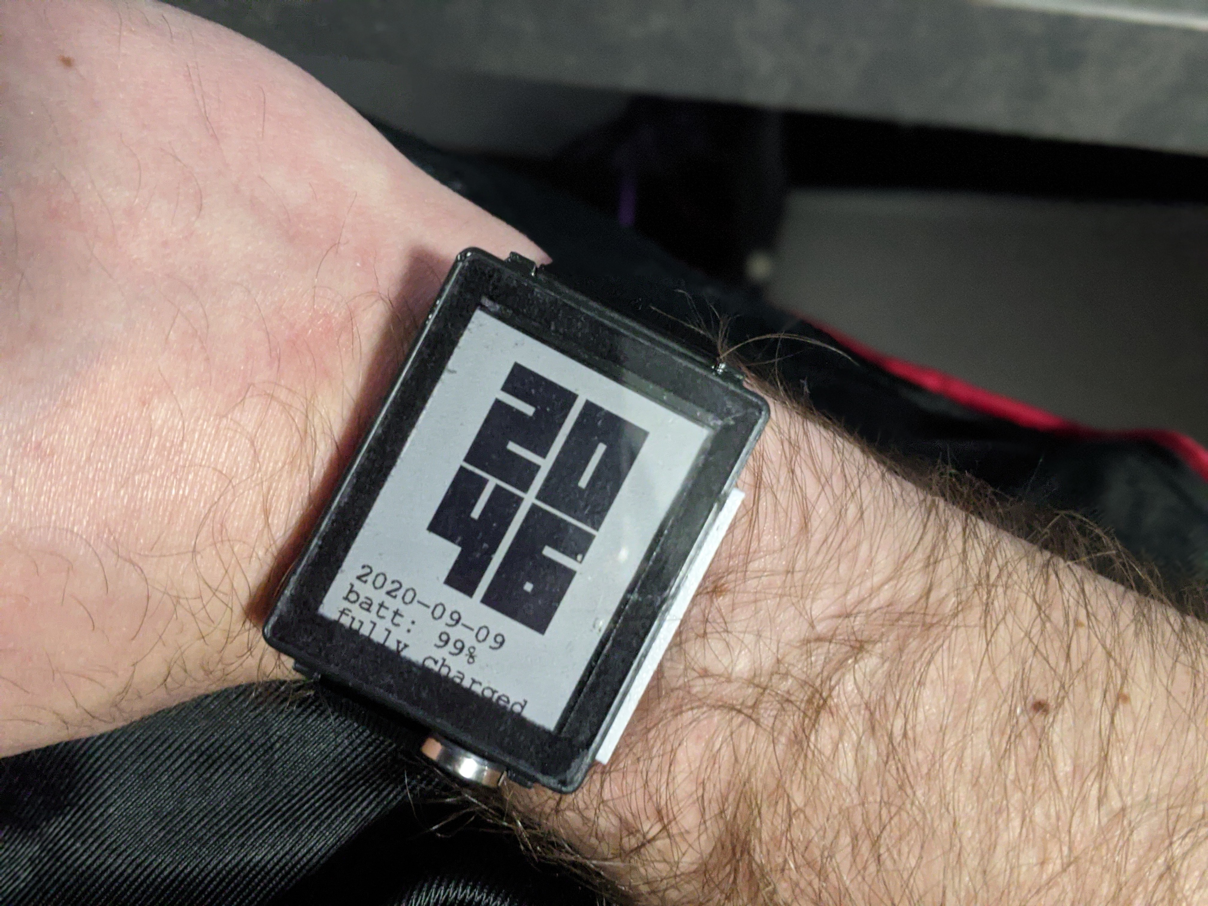
09/10/2020 at 01:01 • 2 comments![]()
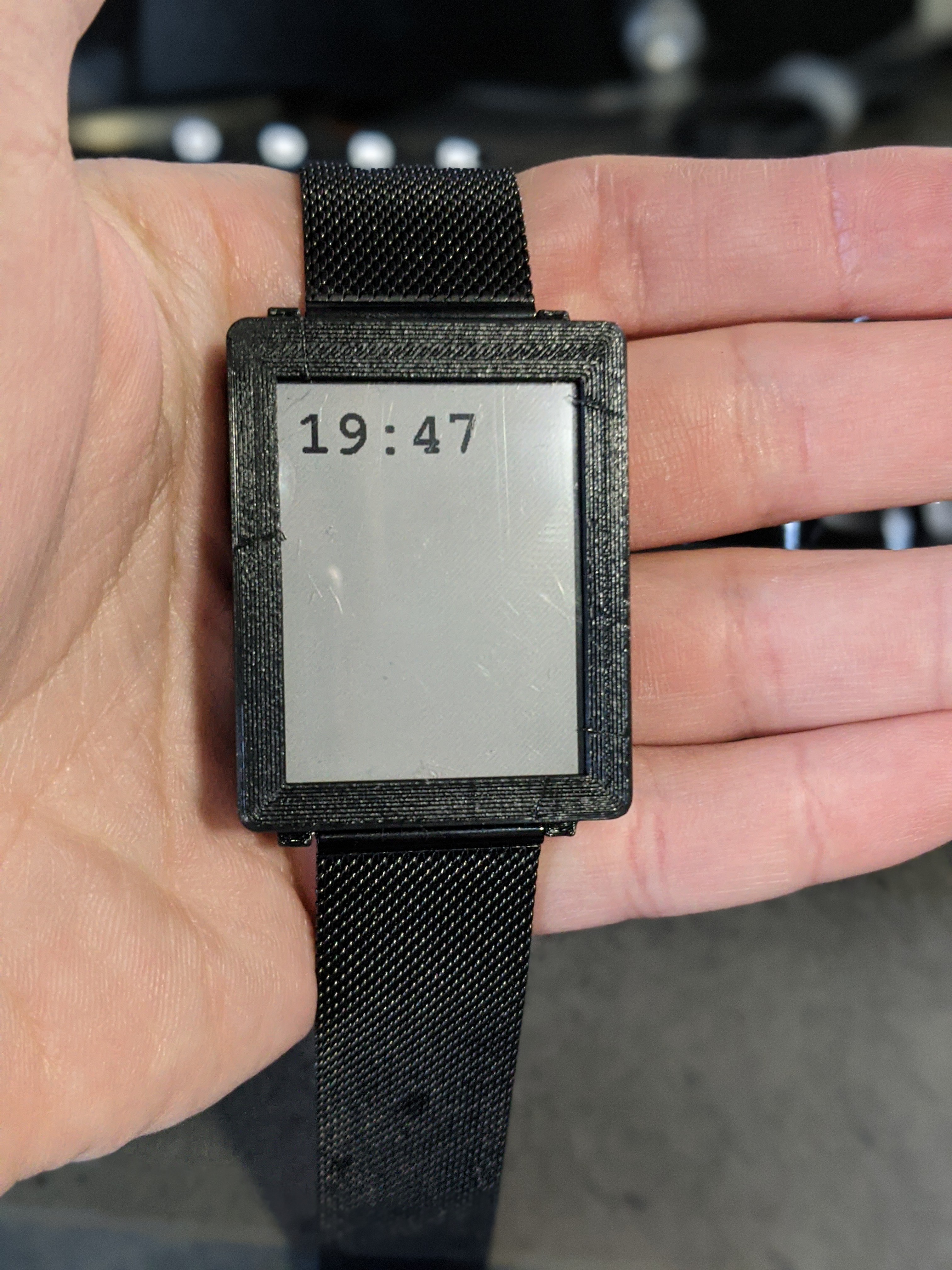
It lives!
The problem with the screen turns out to be something with the cable, but I've found that when it's smashed into the side of the case, it's bent in *just* the right way such that it works. I'm still going to eventually replace it with a new one, but seeing as that won't ship until mid-November, I'm glad I can keep working on it until then.
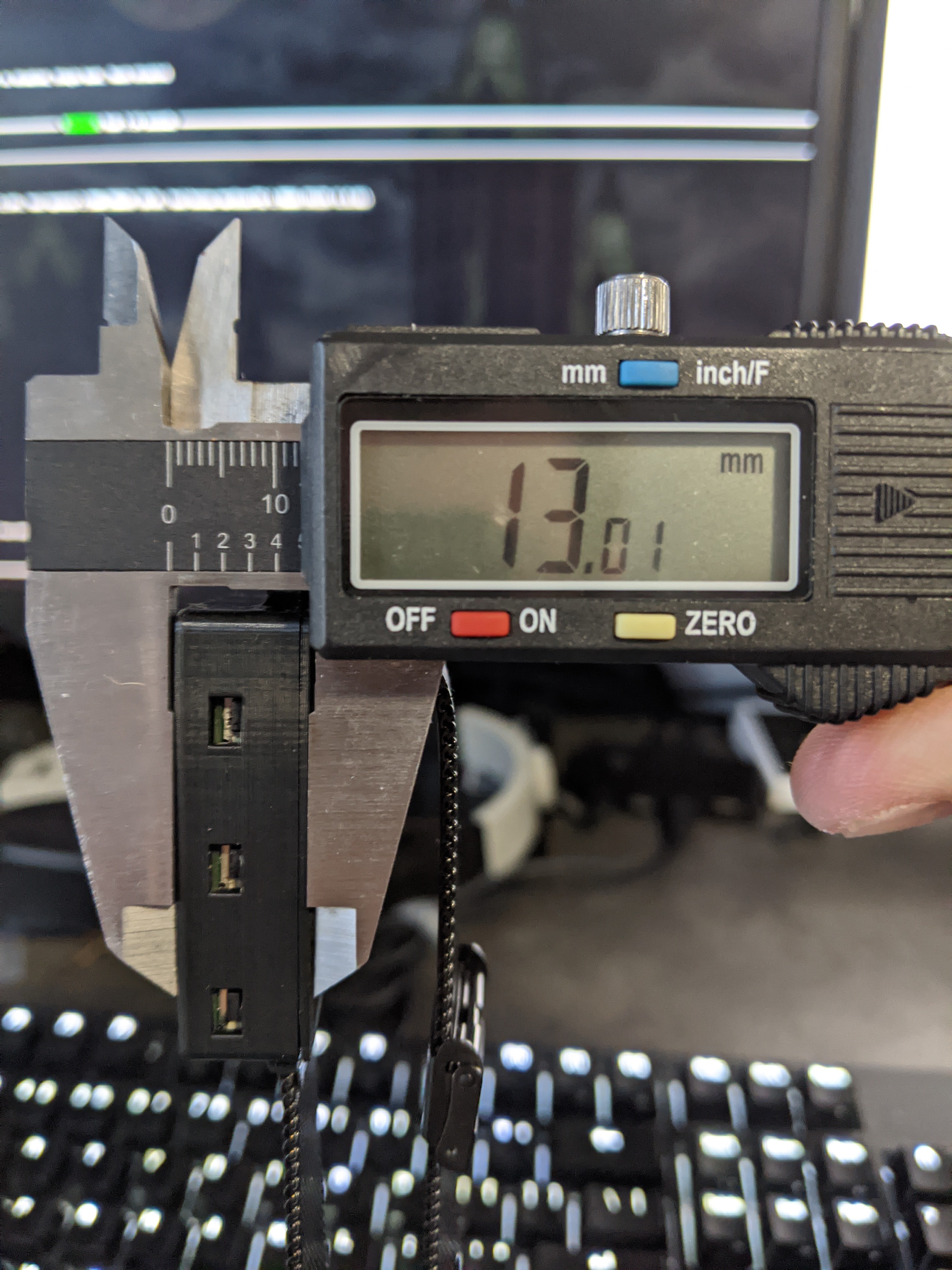
The white strip on the side is a TPU (flexible filament) strip that covers all three buttons, and lets me actuate all three individually without having to have three externally-visible buttons. It also provides a nice contrast to the black plastic case. This watch is also half a millimeter thicker than the previous one I posted, owing to a 1/32" acrylic protector set into the top. The metal bead near the bottom is the side view of a magnetic USB connector for easy charging.
The next version of the flex cable is on its way, and should be here in a few weeks. Until then, I think the watch is ready for (extremely basic) daily wear.
-
A Setback
09/04/2020 at 00:18 • 0 commentsLast night, I finished assembling a slightly (1mm) thicker version of the case that included 1mm of protective acrylic for the screen. Everything was working great, and power consumption (according to the MAX17262) was remarkably low. I plugged in the watch and uploaded some new code and... nothing. The CPU went unresponsive. I plugged in my ST-LINK to the SWD ports of the CPU, which only succeeded in frying a voltage regulator. The ensuing debugging marathon lasted until 5am, and involved replacing nearly every component of the watch, including the CPU, PCB, and four voltage regulators (okay, the same voltage regulator four times. It took me a while to figure out that the SWD debugger providing 3.3V on the normally-2.8V VCC line was burning it up). I may have also damaged some of my USB cables or ports, since the watch only enumerates on some of them. I finally got everything reassembled today, and everything works... except the screen. After a long struggle making sure there were no bridged pins anywhere on the connector, I concluded that I must have somehow fried the display at some point. I don't know exactly how; my only theory is that I somehow bridged the 5V power supply to the 3V data lines at some point. Whatever I did, all of the pins on the connector have the expected values when I probe them, which confirms to me that the problem is with the display and not the MCU.
So no big deal, right? A minor setback, but I can just order a replacement (or two, in case I do this again). Well, that's the setback. The display I'm using for this project is apparently only sold through Digikey, who is out of stock until roughly mid-November. I can continue development using one of the other variants, but unless I buy the 01 variant and slice off the frontlight, it's not going to fit in the case. That would have cause other problems, since the PCB is braced against the frontlight assembly. I've emailed FlexLighting and Sharp, both of whom have been helpful in the past, to see if there's anywhere else I can get the display, with or without the light module attached. If I can get it without the light, I can design my own lighting solution (though I'd prefer not to). Otherwise, I might have to wait until November to have a fully-working watch.
Ugh.
-
Rev 3 Assembled
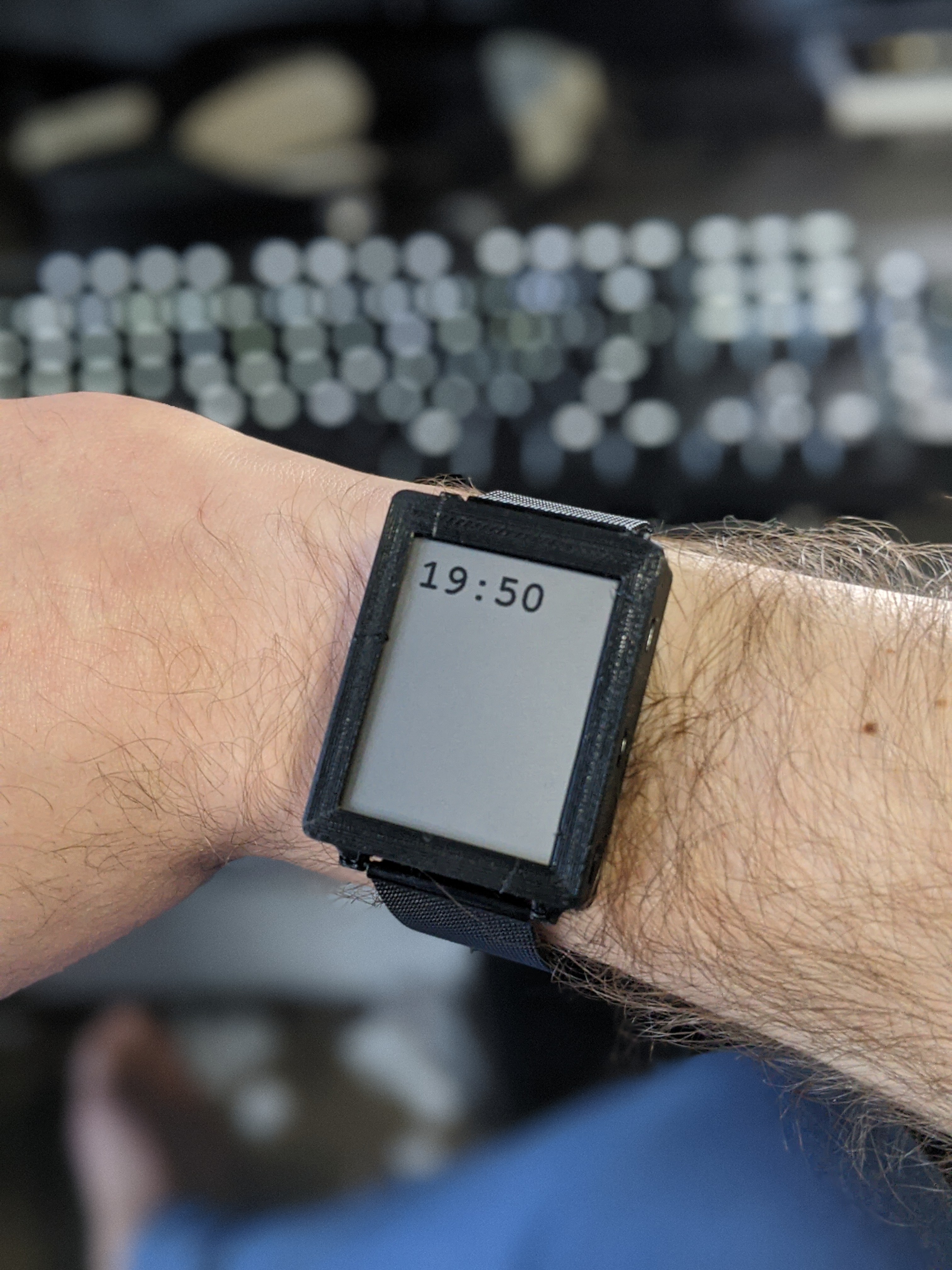
08/31/2020 at 03:58 • 4 comments![]()
It's a watch! Revision 3 (technically 3.1, since I cancelled the rev3 order before it started production and made a tiny tweak) is here and assembled, and it's extremely wearable. It's astounding to me that for $20 USD I can have a circuit board custom-fabricated, flown halfway around the world, and in my hands in under a week. And that 75% of that cost is shipping!
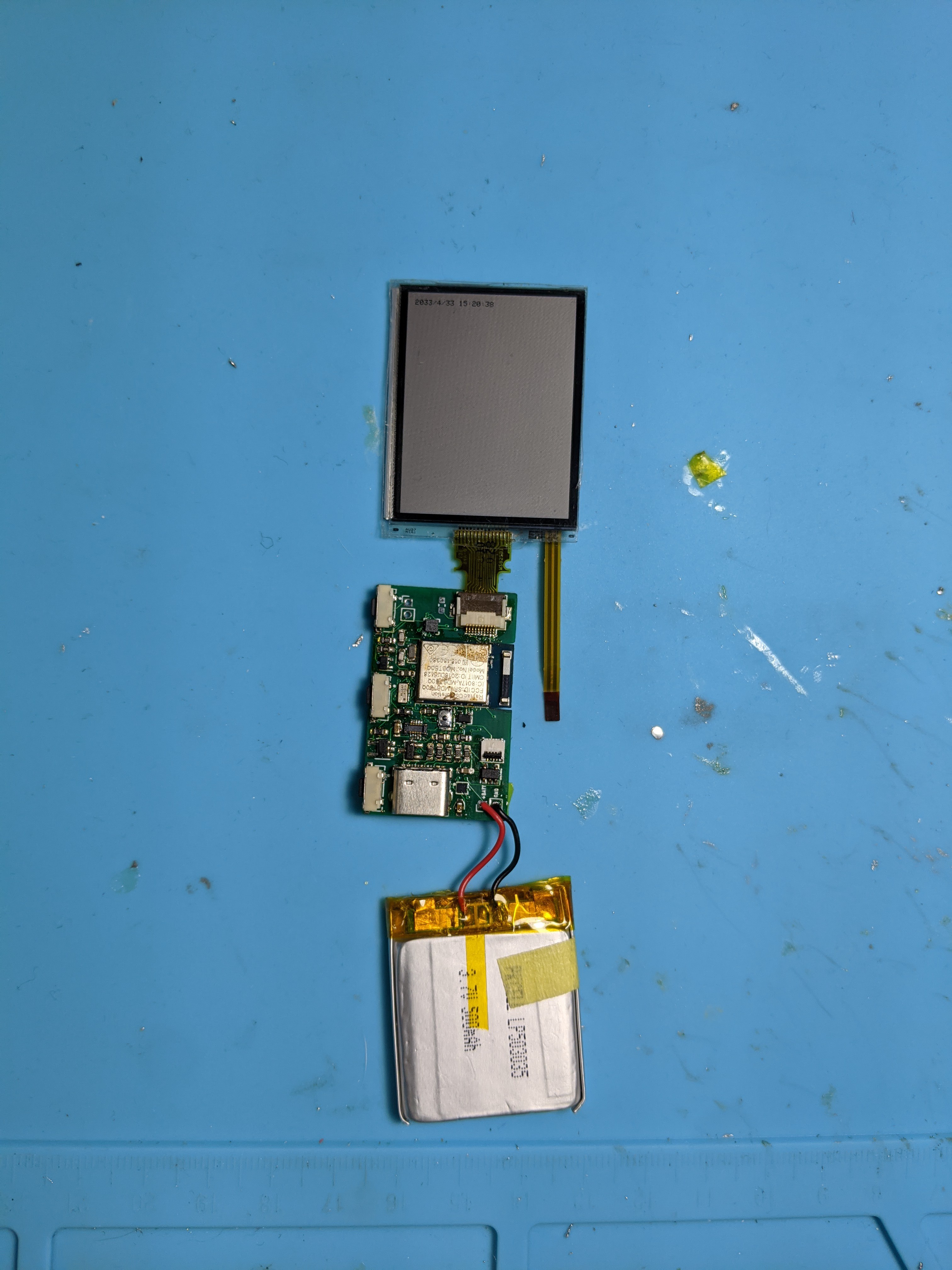
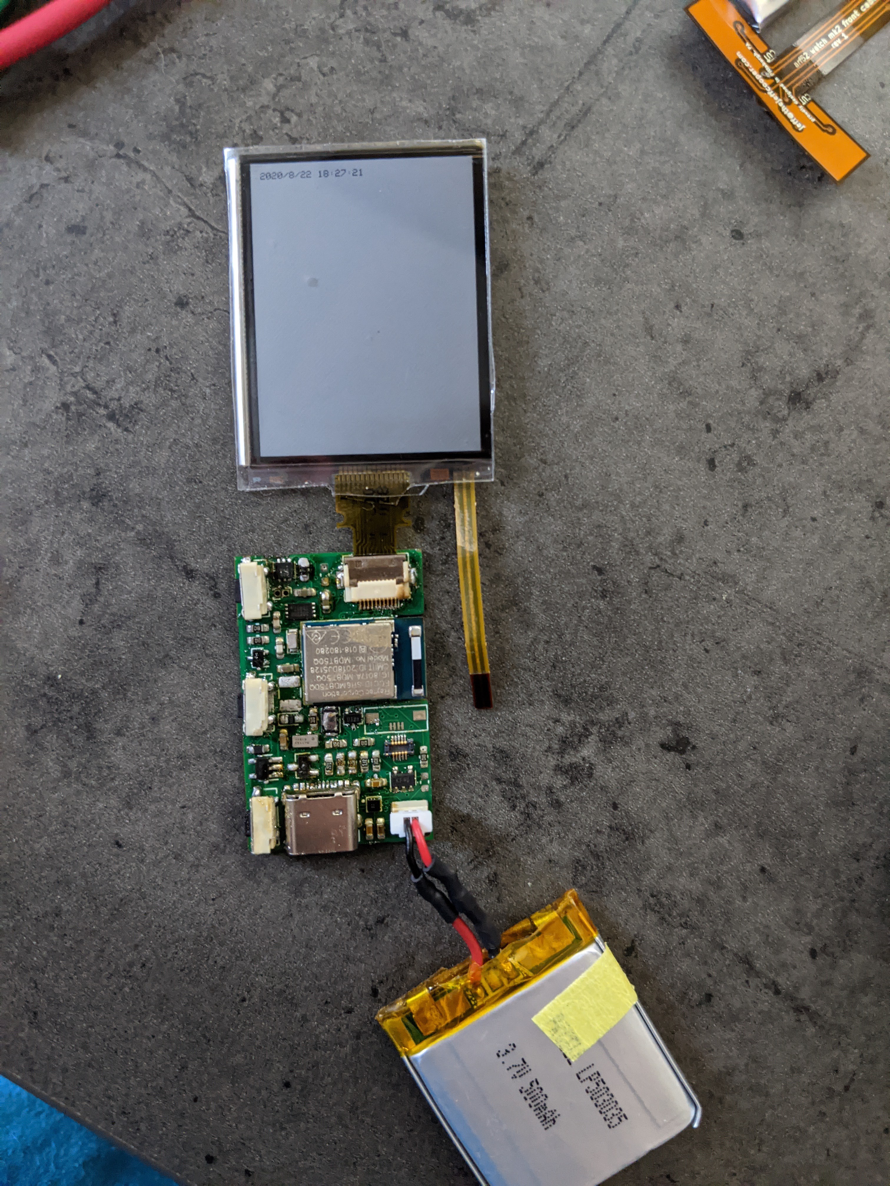
Rev.3 is likely the last major revision for a while until the software is further along (though I might update the Flex PCB that holds the flashlight.. more on that below). Here's what it looks like out of the case:
![]()
The ribbon cable hanging off the side of the screen attaches to the connector just above the battery, in the lower-right corner of the board. Overall, it was time-consuming to assemble, but not amazingly difficult. Keeping all of the components on the top side ended up being hugely helpful, since it meant that I could heat the board from below and not risk blowing any components out of position with my reflow gun.
I haven't fully tested everything, but here's what I do know:
- The frontlight circuitry works, though the protective film that I applied to the screen way back when makes the light hard to see. I may also need to lower the current-limiting resistor on that LED (it's currently 1k).
- The RTC works, and as long as I keep power connected, doesn't seem to have any issues.
- The accelerometer and fuel gauge enumerate on the i2c bus, but I haven't tested them beyond that
- The buttons seem to work. This isn't a surprise, but it's nice to know. I did set one of them to "reboot into bootloader mode," meaning that I don't have to have access to the reset switch to flash the watch. Eventually, this will be a menu option.
- I included circuitry to drive a small vibration motor, and since I had some lying around I threw one in. It didn't immediately work, but I don't know if that's because the the resistor value is wrong, the soldering is bad, or the pin mapping in code is wrong. I'm inclined to believe it's the resistor, but I haven't bothered to replace it with a smaller one.
- The flashlight (an XM-L2 flashlight LED) mounted on a flexible PCB is giving me some trouble. No matter what the input level is, the LED is always on. I've resoldered every piece along the path to no avail; my only remaining theory is that I accidentally shorted the GPIO that controls it to VIN at some point and I need to replace the MCU. Since that's a bit of a hassle, I haven't done it yet, but probably will tomorrow. The flashlight PCB worked fine with rev. 2, so I know the schematic is sound. I did have an interesting experience with the 3ohm current-limiting resistor getting hot enough to desolder itself at one point, so I've replaced it with a higher-valued one for the time being. It's still plenty bright. The only real problem with the layout at this point is that the mechanical position of the connector has changed, so the flashlight and buttons that go on that side of the watch are no longer centered on the watch body. A new revision of the PCB can fix that, but since it takes a few weeks to build, I'm going to print a case with the cutouts offset.
The next thing to do is to make proper mounts for the buttons in the case and print a new version. I may also sand+paint a version of the case so I have something presentable, since I have a family function coming up that I'd like to show off the watch at.
The next few updates are likely to be about software. I'll post the code and schematic soon too. In the meantime, some more glamor shots:
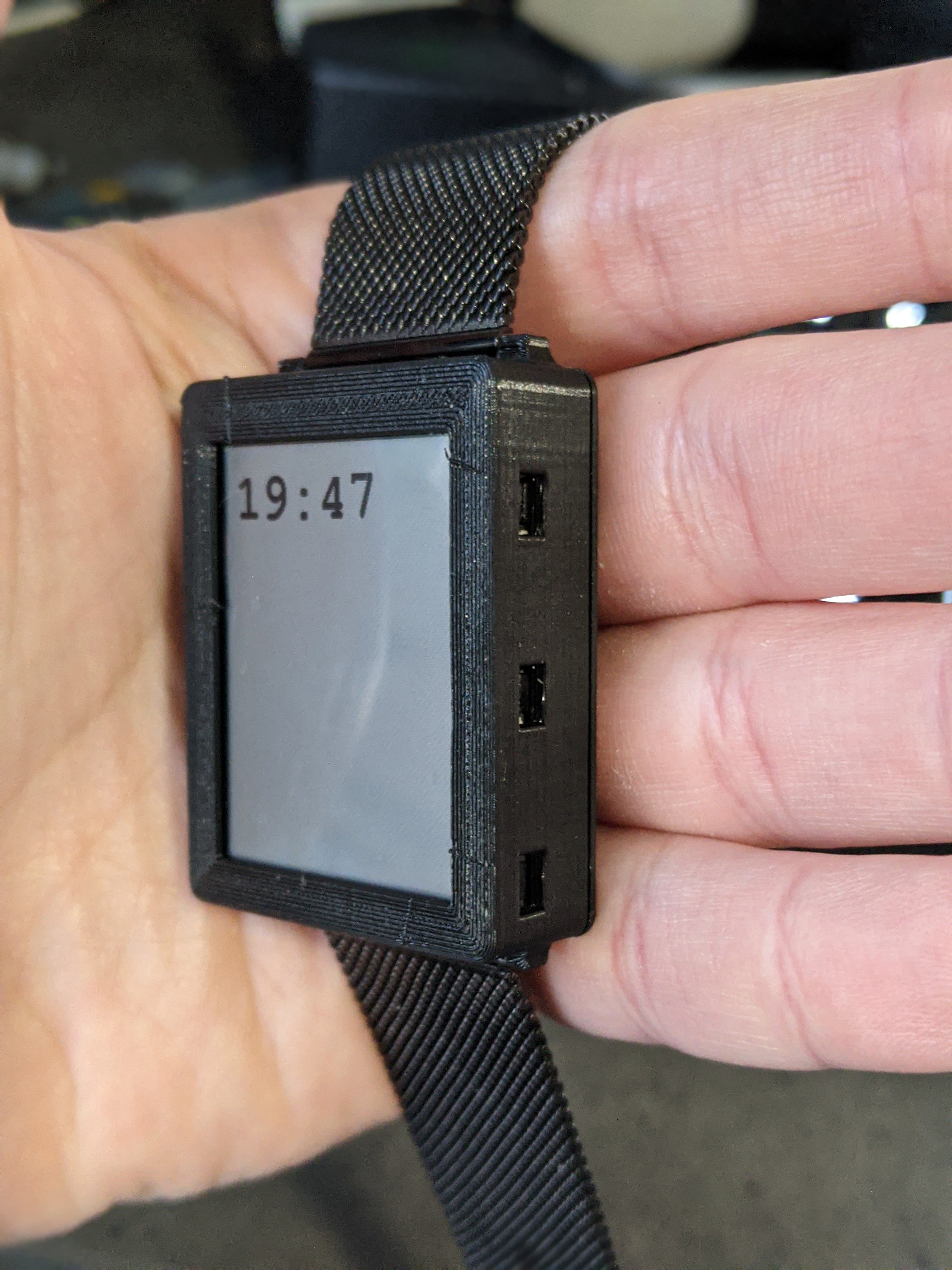
![]()
![]()
![]()
The case is designed to fit any standard 22mm watch band. The one attached in the picture is this one (note if you buy it: it doesn't come with pins!).
-
rev.3 Ordered!
08/23/2020 at 05:49 • 0 commentsRevision 3 of the board is ordered! It's very similar to rev.2, but with the following changes:
- Dropped from 4 layers to 2, but kept all components on the top side :)
- Removed 5V boost converter that didn't work anyways
- Removed external flash chip, since I discovered the nrf52840 has 28k of internal flash available to the user
- Removed MAX17262 bypass jumper, since I've confirmed the IC works okay
- Repositioned connectors for the backlight and flex pcb to better fit together mechanically, and repositioned some components to accommodate
- Added BMA400 accelerometer
- Moved buttons a little closer to the edge of the board
- Converted battery connector to 2mm pitch holes rather than a JST receptacle
JLCPCB is having some issues with their online ordering system (the gerber analyzer appears to be broken), so I have to wait until they manually approve the board before it goes into production. I also threw together a quick USB-C female to USB-C female board with the VBUS lines broken out so I can do current measurement while still having access to the serial terminal. Hopefully I'll have the boards by next weekend and I can put together the first wearable version of the watch!
-
Technically, it's a Watch!
08/22/2020 at 23:32 • 0 comments![]()
This is an exciting milestone: I have a portable device that can keep track of time! I've finished soldering all of the components on the board (except the header for the LCD backlight), and it all seems to work. The only problem is the MAX17220 stubbornly refuses to cooperate: after letting the magic smoke out of a few, I finally replaced some of the components that JLC soldered on and got it "working"... but it doesn't actually boost to 5V like it should. Instead, it seems to buck USB to about 3.4V, and do nothing to the 2.8V input voltage. I've replaced and reseated the component enough times to be decently confident that it isn't an assembly problem. I actually replaced the one on the board in this picture with a fresh one after taking this picture... and it smoked as soon as I plugged it in. HOWEVER: the display still worked at 2.8V, it just had a nasty flicker when it updated. The display's datasheet says it can handle a maximum voltage of 5.8V, which is safely above the maximum 5.25 for in-spec USB... so I made a solder bridge between VIN and 5V, and the screen works great! The next revision will just not bother with a 5V booster, and I'll just run the display a little out of spec. Yay for simplicity!
Otherwise, the buttons (mounted on the left side of the PCB in this picture) and the flashlight (attached to the flexible PCB at the top right of the picture) work fine. There's a small risk of something overheating, but the flashlight LED (Cree XM-L2) is brighter than the one on my cell phone, which I'm very pleased with. I'm getting data from the MAX17262 fuel gauge IC, but I haven't yet gone through any sort of calibration or setup. I haven't tested the flash memory, but seeing as it's on the SPI bus with the screen I'm not immensely worried.
I do think I'm going to need to come up with a better solution for the battery, though. even the tiny JST-SH connector is huge compared to the rest of the board, and the heatshrink-protected cables aren't flexible enough to assemble the whole thing in its case. Now that I'm reasonably confident that I'm not going to set anything on fire, I'm probably just going to leave holes to solder battery leads in to.
My next priority is to get rev3 of the board built and sent to the fab; I expect it to look an awful lot like rev2. I will probably move some low-profile passives to the bottom of the board, though, so that I can switch back to a 2-layer board. The faster turn time seems worth it to me.
-
Press C5 to Boost
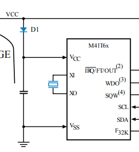
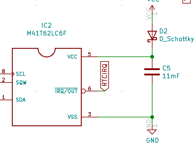
08/21/2020 at 04:55 • 0 commentsWhat's wrong with this picture?
If you answered "nothing," you're absolutely right. It's taken directly from the M41T6x Datasheet, and my schematic has a an identical block (minus the crystal, which is embedded in the LCC package that I'm using):
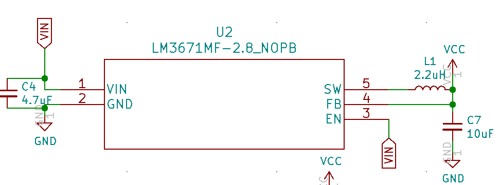
Now, what if I told you that, when I soldered in the 11mF supercapacitor and plugged it in, I measured voltage across it higher than VCC. Significantly higher, actually: VCC on this board is 2.8V, but after leaving the circuit plugged in for a while, I measured 3.2V (and climbing, in spurts every few seconds) across the capacitor. So what's wrong? Well, let's look at where VCC comes from:
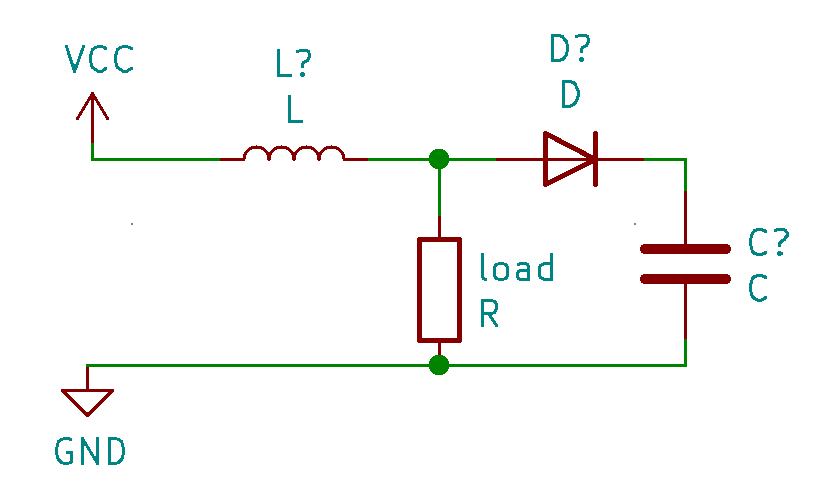
Again, nothing special. This schematic, including all of the component values, is taken directly from the LM3671MF datasheet. But let's look at a simplified version of the circuit they form together:
Here, the resistor stands in for the load provided by the MCU and other various components. If you have a background in electronics (and I don't, so hopefully someone in the comments will correct the mistakes I inevitably make), you might also recognize this as very similar to the layout of a boost converter: if you replace the load resistor here with a switch and rapidly open and close it, current will build up across the inductor when the switch is closed, then be forced through the diode into the capacitor when the switch is open. By repeating this process faster than the capacitor discharges (through leakage or load), the voltage across the capacitor can get much higher than VCC.
Now, when we look back at our original circuit, the behavior I saw starts to make a bit more sense. The program running on the microcontroller periodically reads from the RTC module via the (hardware) I2C bus, and then prints the results to a serial terminal (via onboard USB), then sleeps for a few seconds. The MCU draws more current when it's working than when it's sleeping, so the current being drawn through the inductor goes up. When the MCU goes back to sleep and suddenly draws less current, the current flows through the diode and into the capacitor, just like in a boost circuit. The feedback pin on the 2.8V regulator is before the diode, so the regulator is oblivious to problem. This explains the spurts of voltage increase that I saw on the multimeter (I don't own an oscilloscope, otherwise I'd have cool graphs attached to this post). Luckily I noticed this before the voltage got so high that it burned out any components.
So what do we do about this? The supercapacitor is in the circuit to act as a backup for the RTC, so that it can keep time when the battery is disconnected or runs out. While I could do something like put in a second regulator on the RTC-side of the diode just to charge the capacitor (bypassing VCC entirely), the simplest solution is the best one here: just remove this part of the circuit. An RTC backup is a "nice-to-have" feature, but this is a smartwatch: when power is reapplied, it can just get the time directly from the paired smartphone. The RTC module has functionality to detect when it has lost power (the "oscillator fail" bit), so it should be easy to know when a resync is necessary.
Thankfully, the current revision of the board is perfectly workable with the capacitor simply removed. The next revision won't include it (an 11mF supercap has a pretty large footprint). I do plan on adding a BMA400 accelerometer, though, which has a built-in step counter and tap detection. On top of that, it has this lovely trailer video that makes me wish more companies made trailers for their ICs.
The new 5V regulators won't be here until Mondayish, so I probably won't have a fully-working demo to post about until at least then. I also haven't tested any of the buttons (I'm confident those will work) or light circuits (I'm less confident...), but hopefully I can do that this weekend.
-
micro-update: yay!
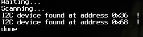
08/19/2020 at 22:18 • 0 commentsI soldered on the new nrf52 module, and it now detects both the RTC and the fuel gauge! Yay!
I ordered more 5v regulators, and I'm going to wait very patiently until they arrive rather than risk frying my display.