 EtchedPixels
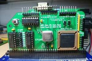
The 16C2552 doesn't need a lot of glue on the RC2014 side. A single 74HCT138 is used to decode the I/O space and allow the card to be placed at 80/90/A0/B0/etc with the second port 8 bytes above. The standard configuration used on non Z80 ports is to put it at 0xC0 and the RTC at 0x0C rather than 0xC0.
The 74HCT138(U2) takes A4-A7 and IORQ and uses them to generate the chip select. The read/write, data and address lines are directly connected to the 16C2552 (U1). A 74HC02 (U3) is used to invert the reset line to give a high reset as expected by the 16C2552, and also to merge the two IRQ lines (INTA/INTB) onto the RC2014 INT line through a diode as the INT line is shared with a pullup on the CPU card.
Resistor packs protect the UART lines from excessive current draw (eg when powered off and connected to a USB adapter). They are arranged so that the one pack buffers the "important" lines and the other one the rest. This allows two of the resistor packs to be omitted if you don't need the more obscure modem lines (DSR, CD, RI etc)
Jumpers allow the RX/TX signals for port A to be connected to the backplane serial RX/TX lines. A third jumper allows the 1.84MHz clock on the UART to be used as the clock on the bus or as a convenient attachment for a flying lead to provide 1.84MHz elsewhere.

SCM with driver posted @
https://groups.google.com/forum/?utm_source=digest&utm_medium=email#!topic/retro-comp/ulCFyvwlwXQ
CM