 Peter Buckley
This build will be losely based of the Sphinx 55 CNC by Sorin Iliesu and custom plates made by Chris Laidlawh. Their design is sadly not open source and their are no plans available. The OpenLRC is designed so you can either 3d print, or cut the parts out of wood. Once you get the CNC up an running you will be able to cut the plates out of aluminum to upgrade the machine yourself. The idea for this project came after i built my MPCNC in fall of 2019. I originally built it with the plan of cutting aluminum, but sadly while very cheap, and very fun to build, the platform is just not stiff enough. The idea was I wanted to transfer all the buget parts such as nema 17 motors and tb6600 stepper drivers that I used to make the MPCNC with the intent to upgrade them later.
0%
0%
OpenLRC - The low cost linear rails CNC
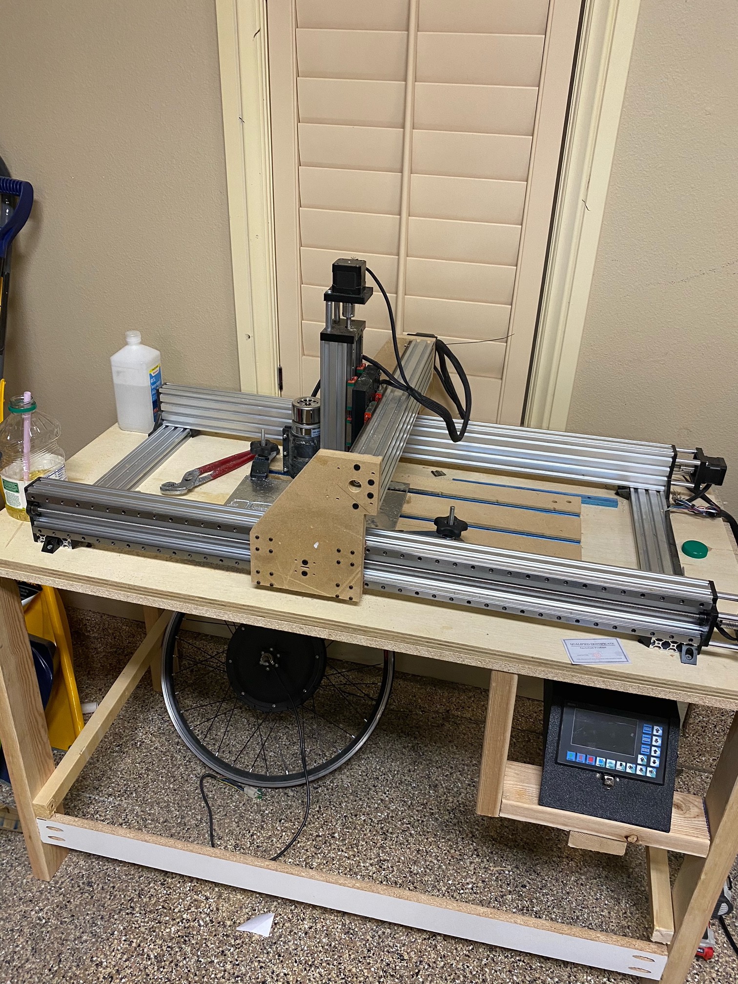
Open source CNC project which uses cheap linear rails from china, and aluminum C profiles for modularity and rigidity.
Become a Hackaday.io member
Already have an account? Log in.
Just one more thing
To make the experience fit your profile, pick a username and tell us what interests you.
Pick an awesome username
hackaday.io/
Your profile's URL: hackaday.io/username. Max 25 alphanumeric characters.
Pick a few interests
Projects that share your interests
People that share your interests
 Electronics
 Issues and Changes
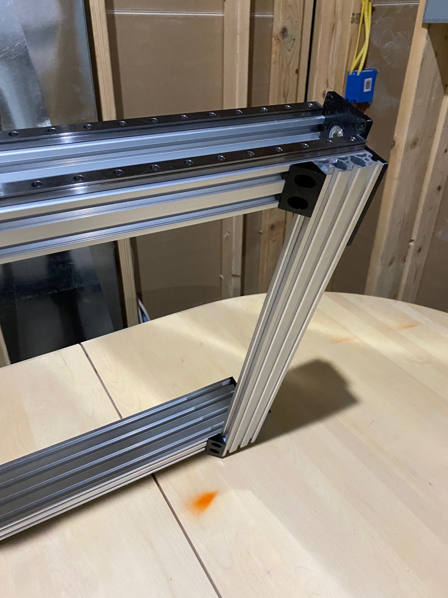
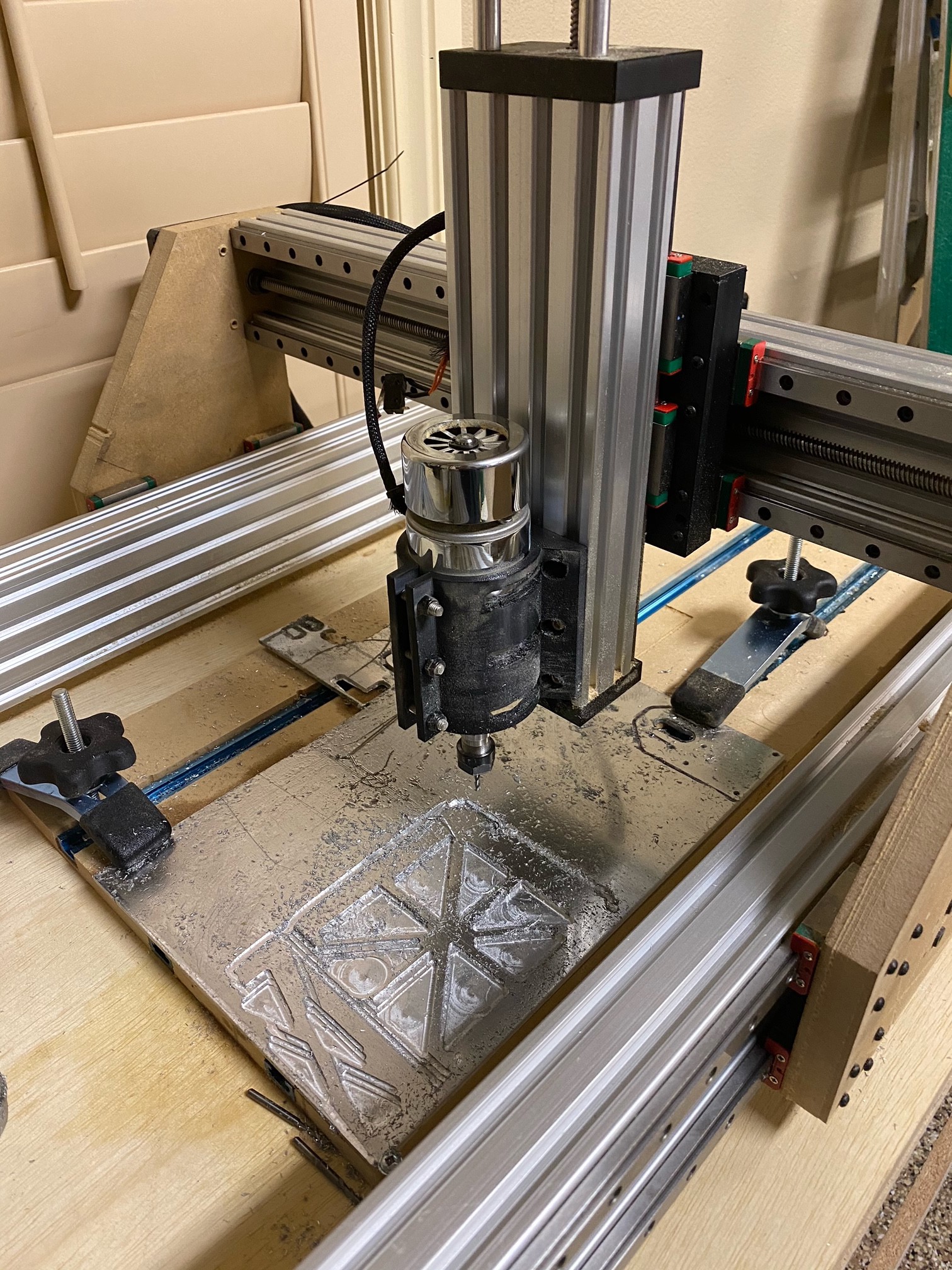
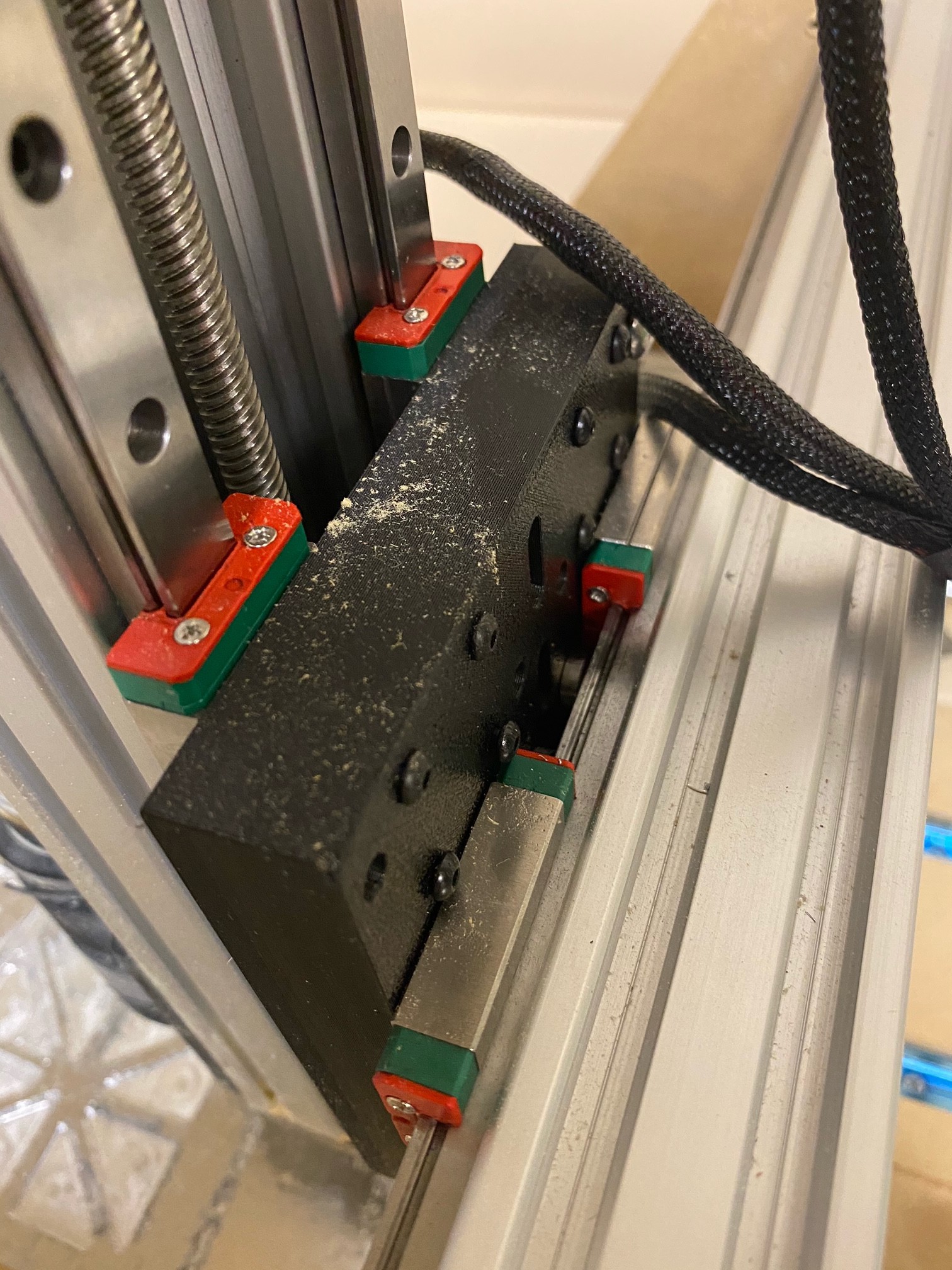
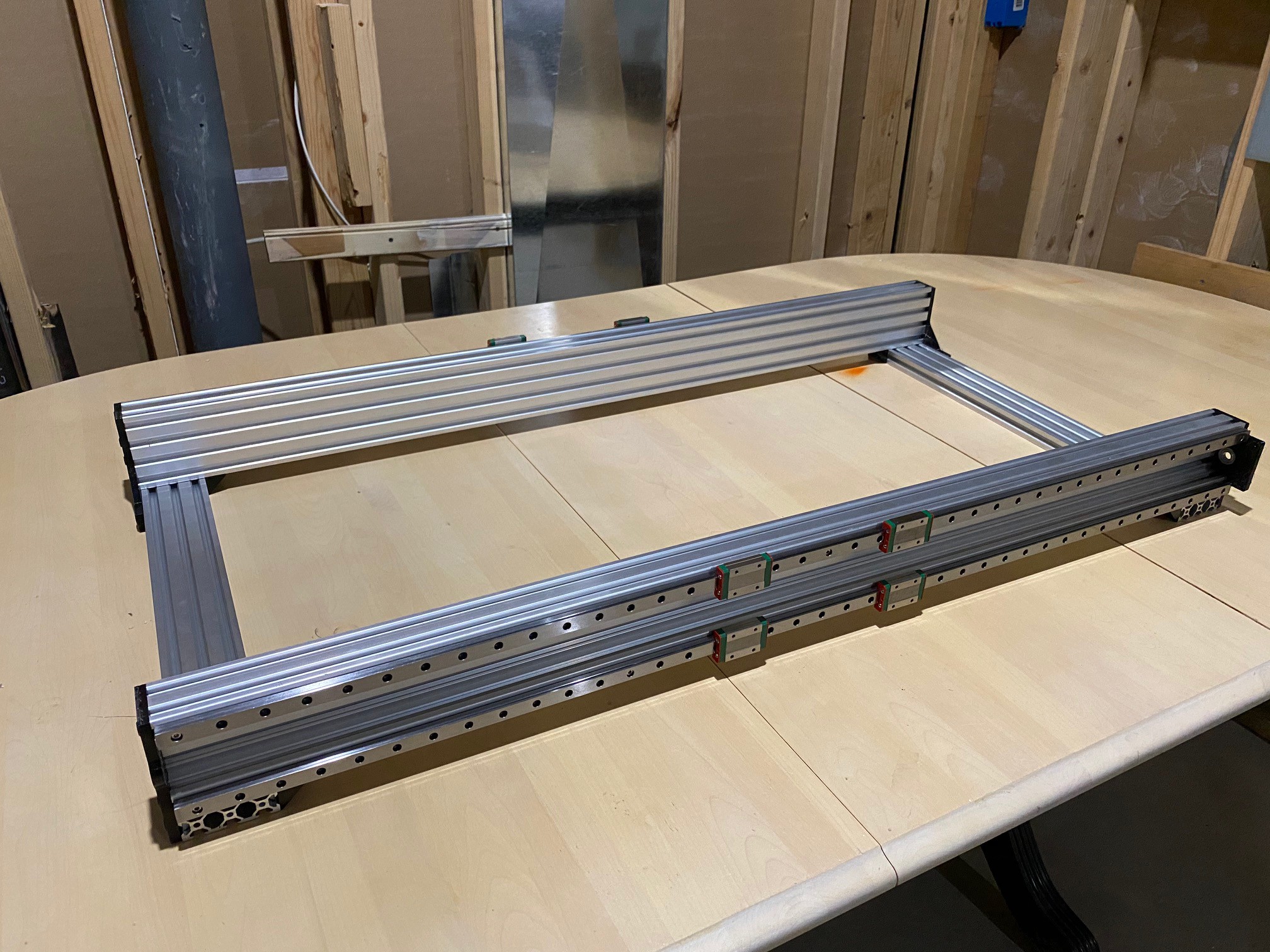 I used 3d printed rail aligners to temporally install the linear rails. Im using MGN12H knockoffs off alibaba. They are each only held on with 4 screws for now as i am waiting for more to arrive. The lead screws are not installed because i mistakenly ordered them all far to short. Right now i am designing the plates for the y and z axis. And will add nother log when those are complete.
 Greg Duckworth
 willbaden
 John Opsahl
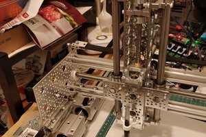
 Ted
Ted
Hi Peter, I like to ask if you completed your work and if youcould share the files. Thank you very much !