 willbaden
Links to Logs-
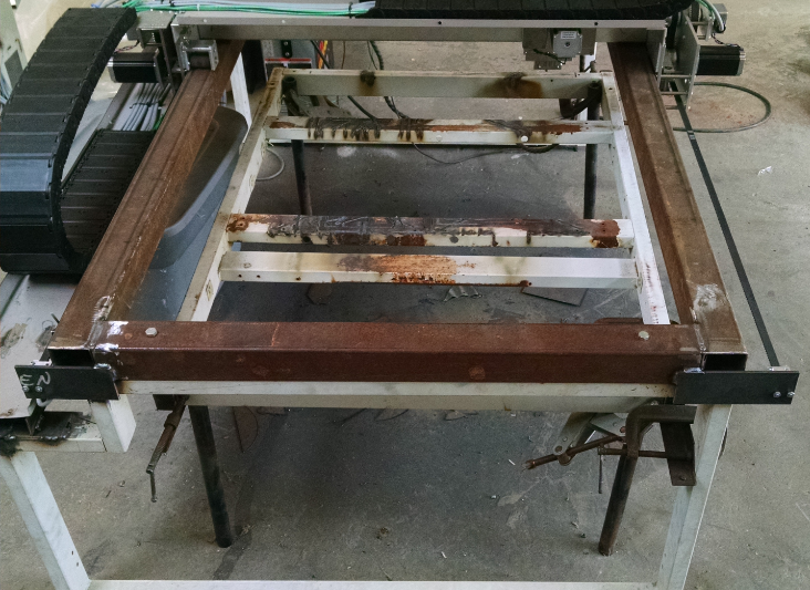
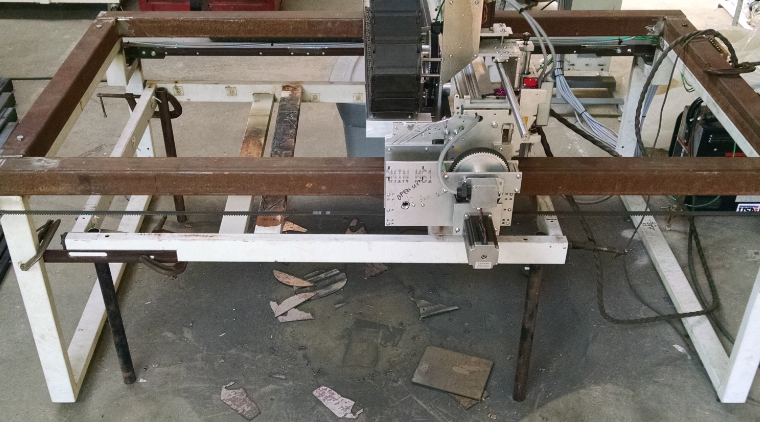
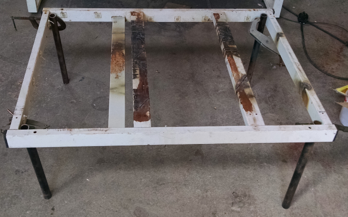
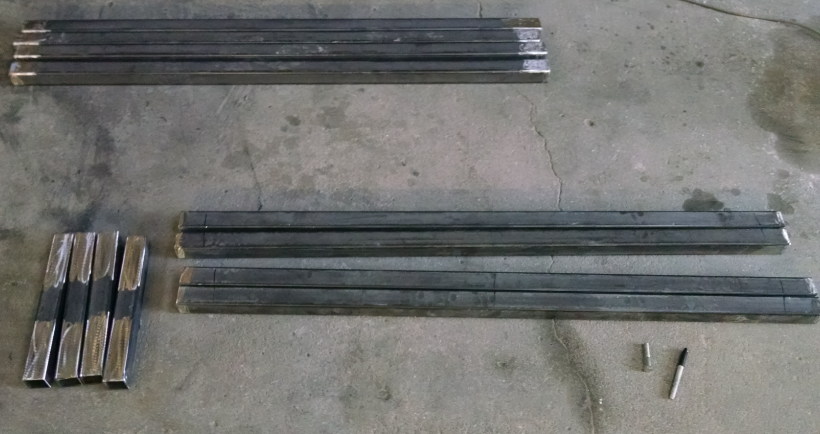
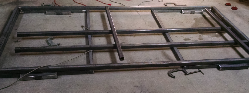
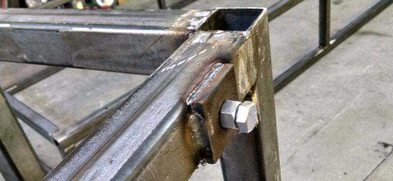
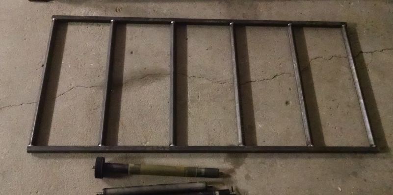
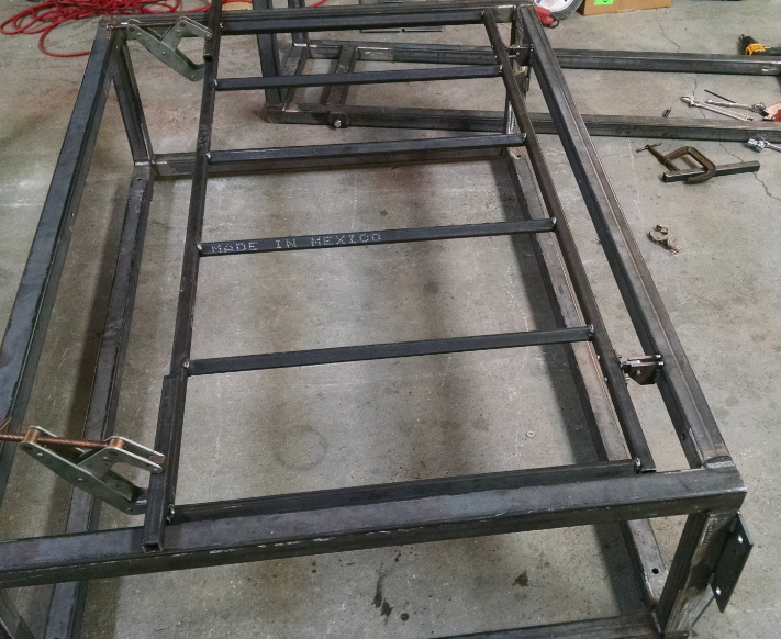
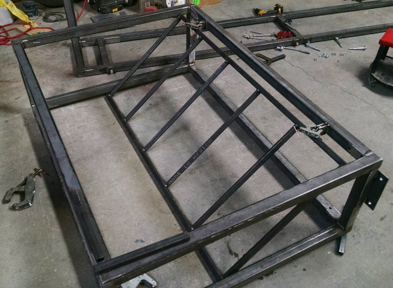
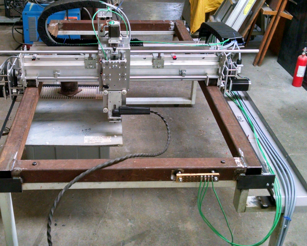
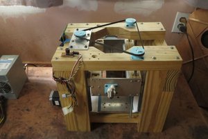
- First Frame Design
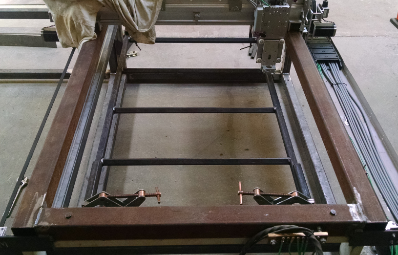
- Y Axis
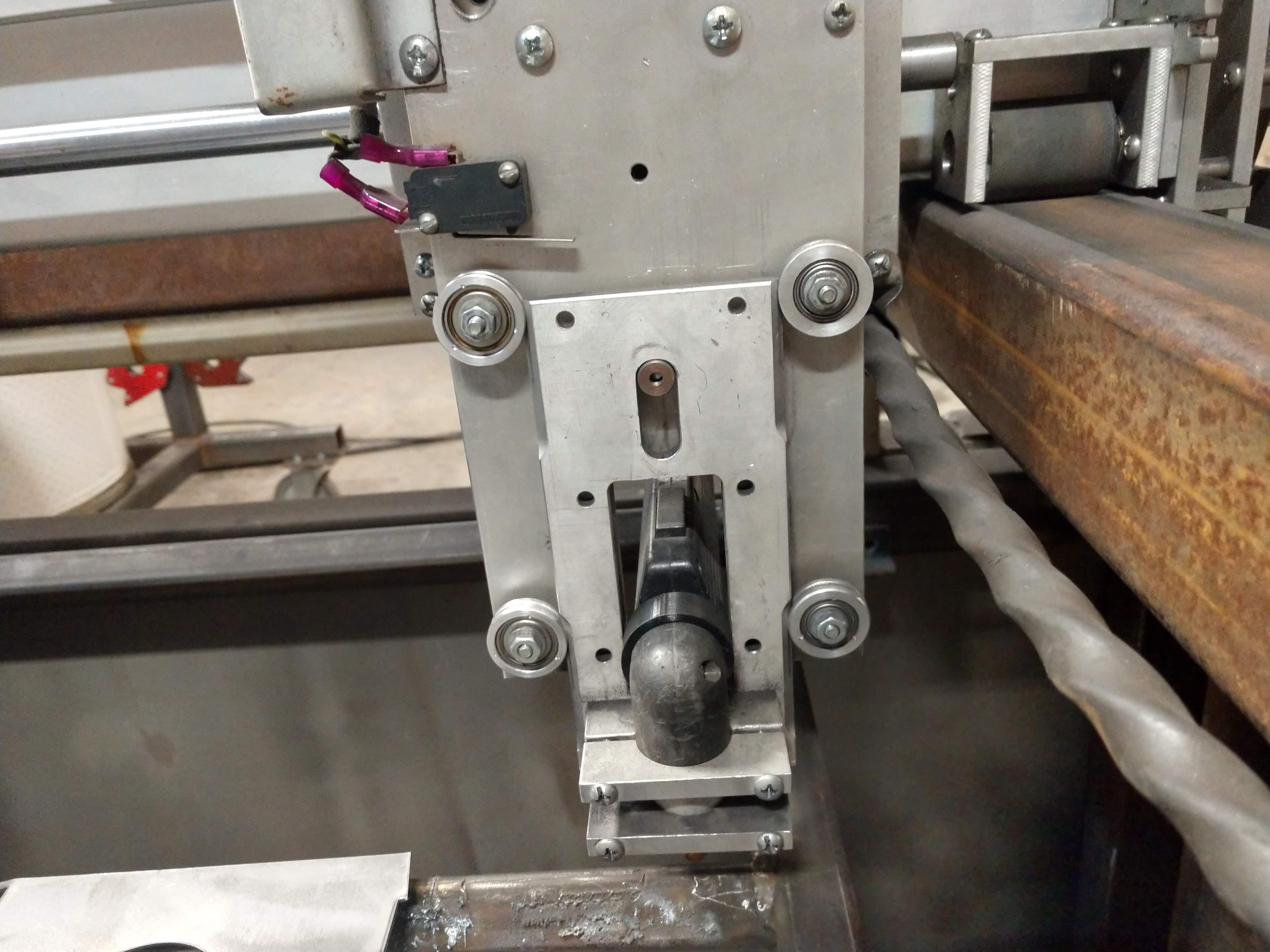
- X Axis
- Z Axis
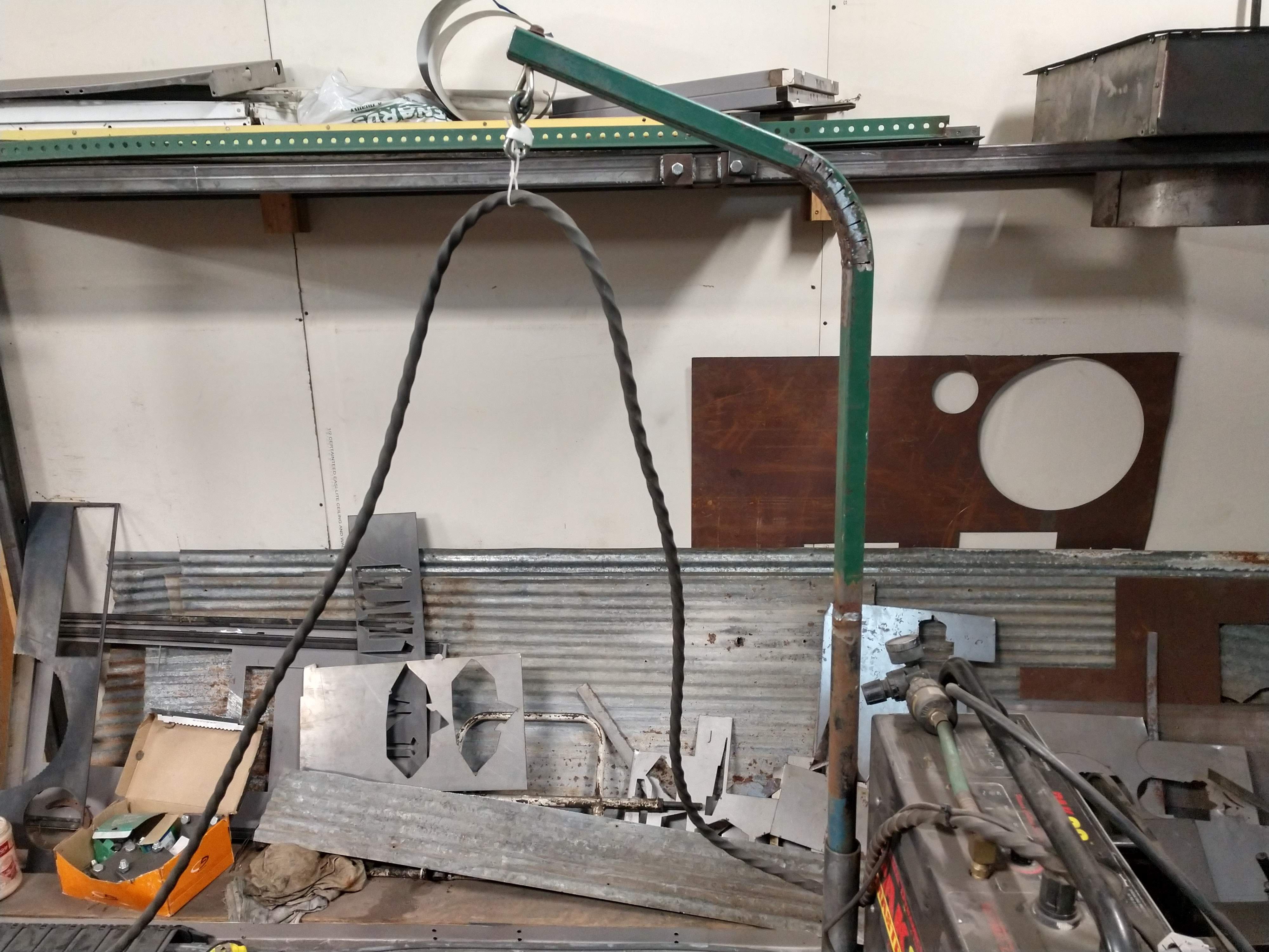
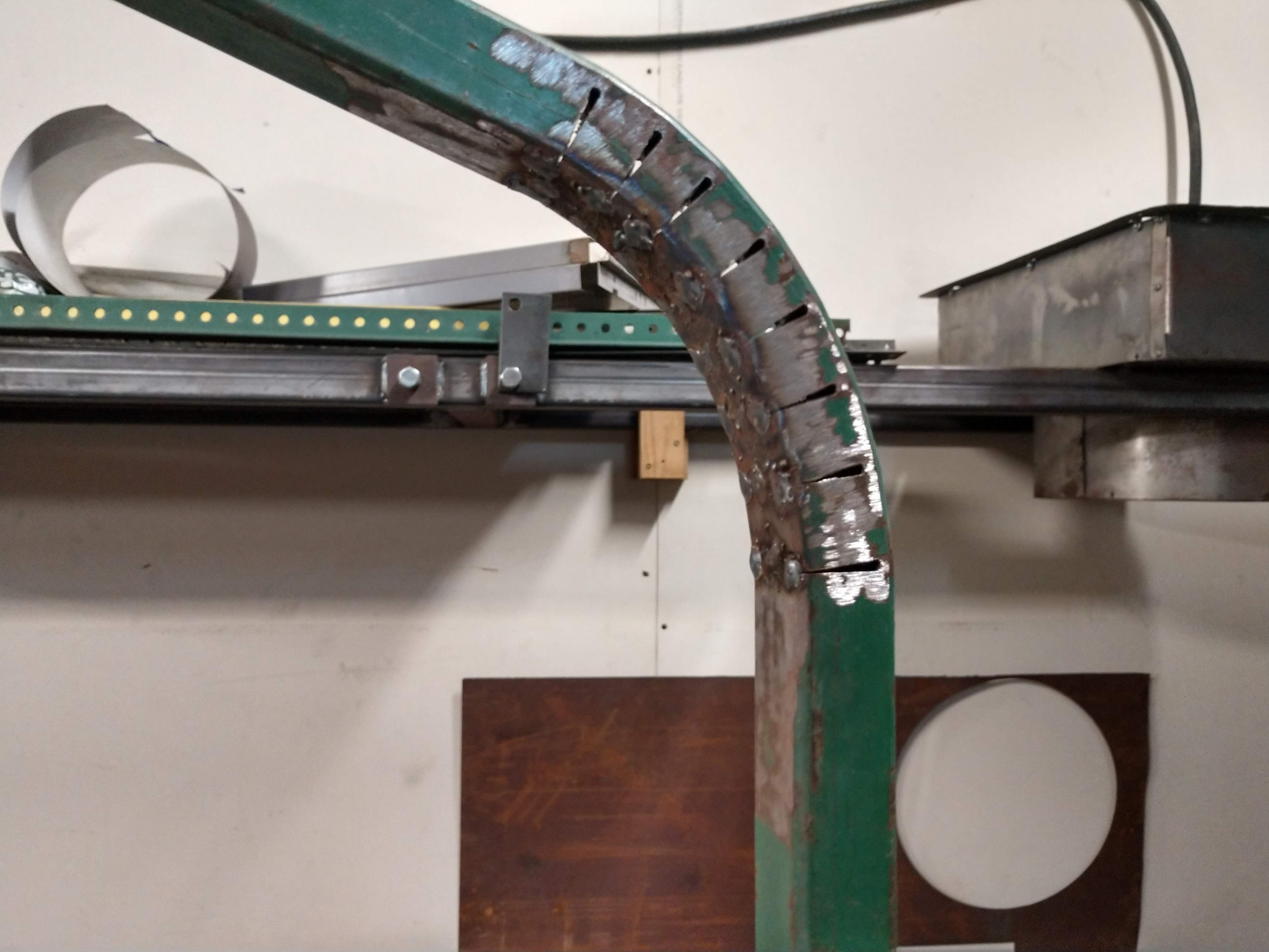
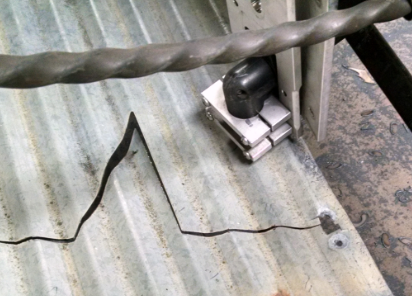
- Cable Routing
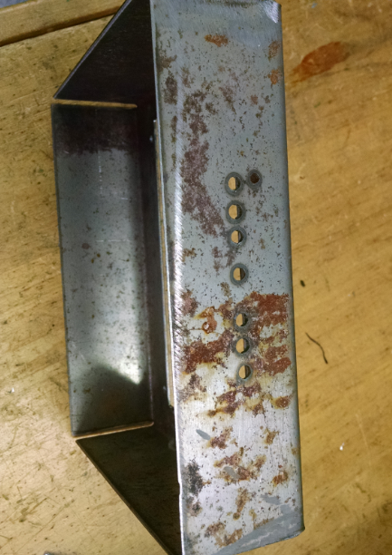
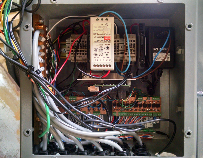
- Stepper Drive Enclosure
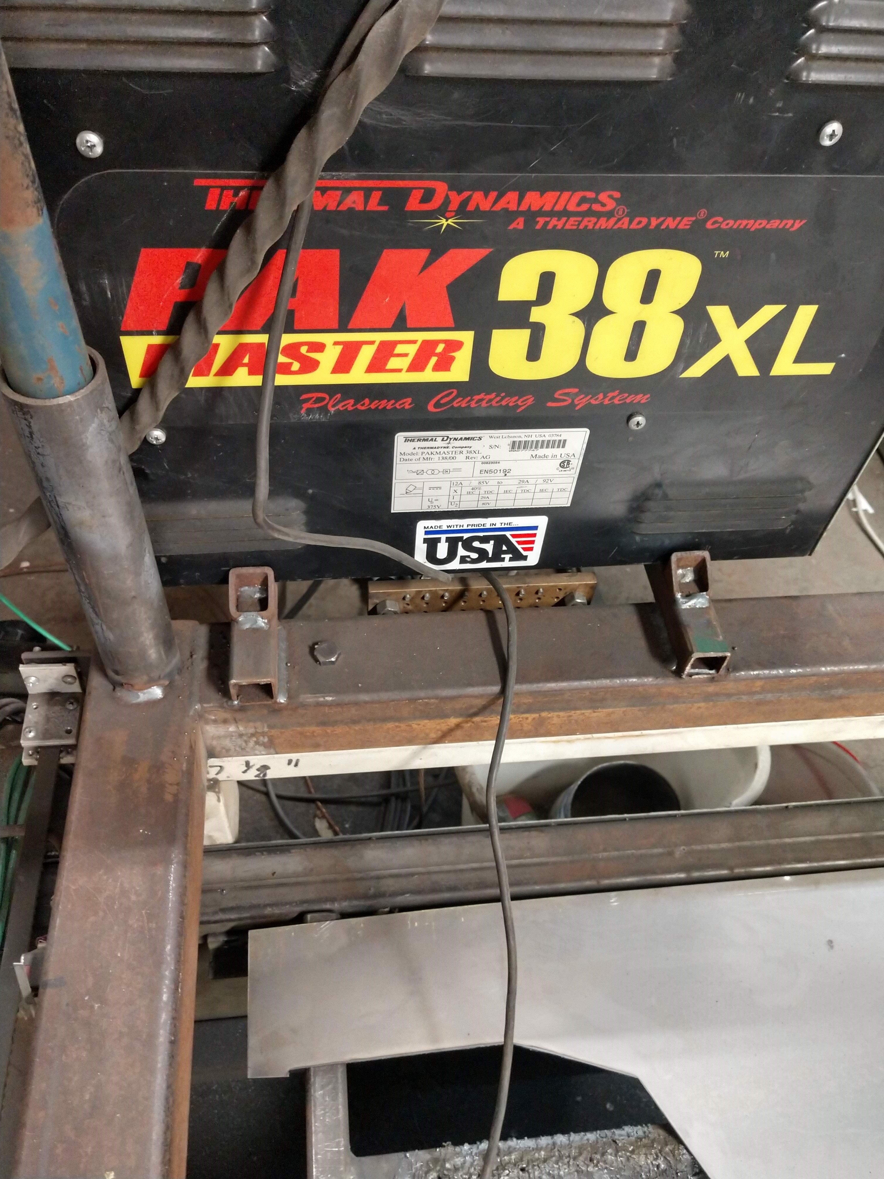
- Plasma Cutter
- Plasma Cutter Delay to Cut
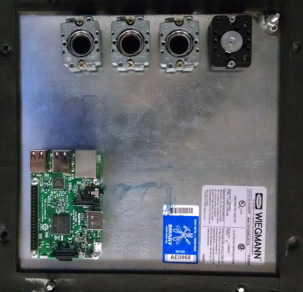
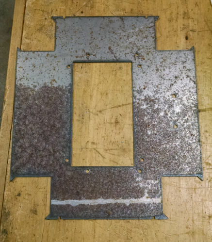
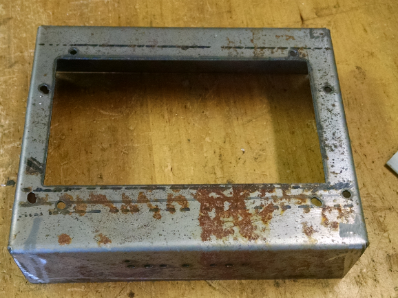
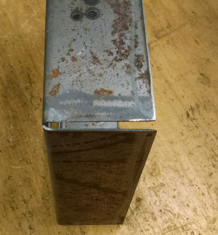
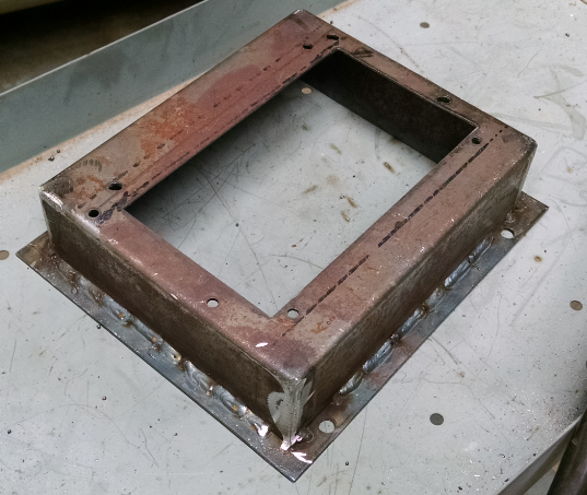
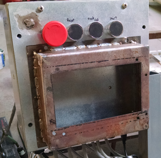
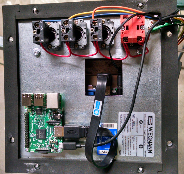
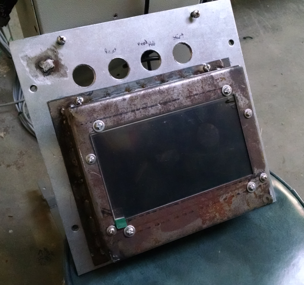
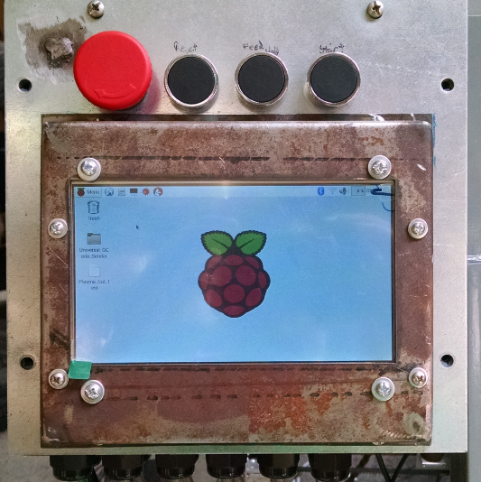
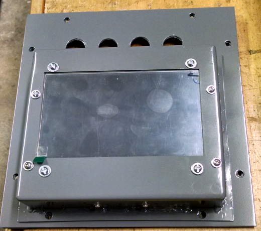
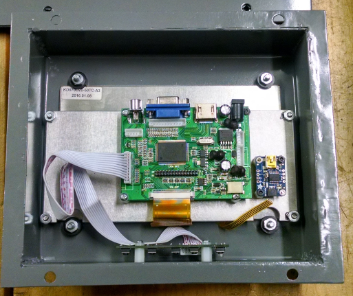
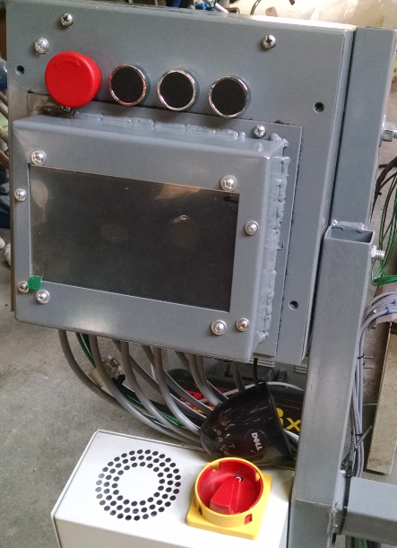
- Controller Box
- Raspberry Pi Addition
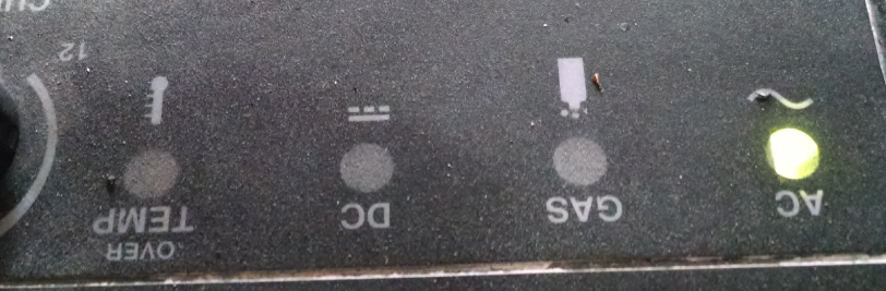
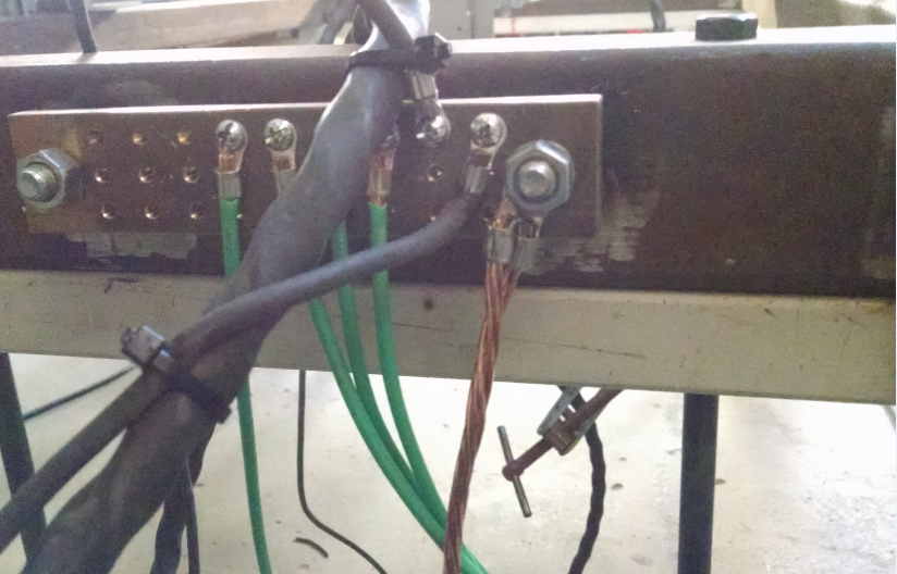
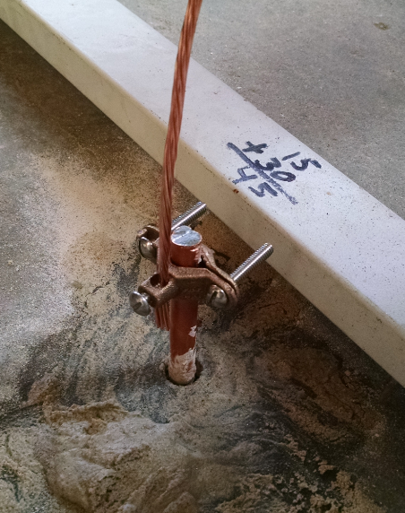
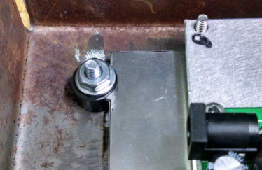
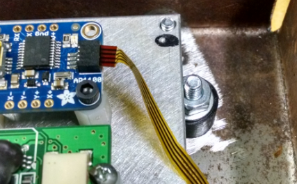
- Chassis Grounding
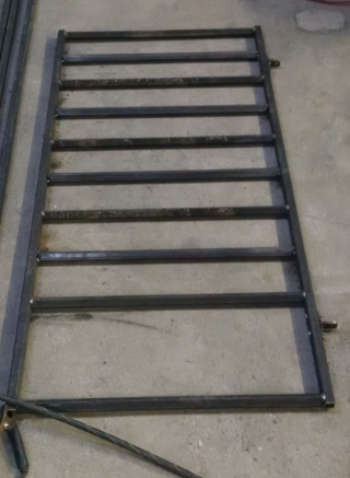
- Material Cut Table
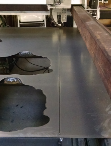
- Exhausted Material Cut
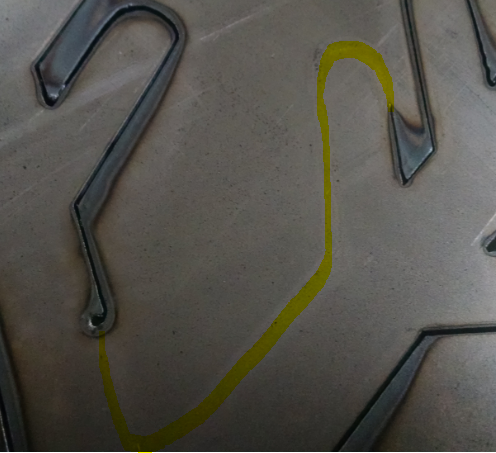
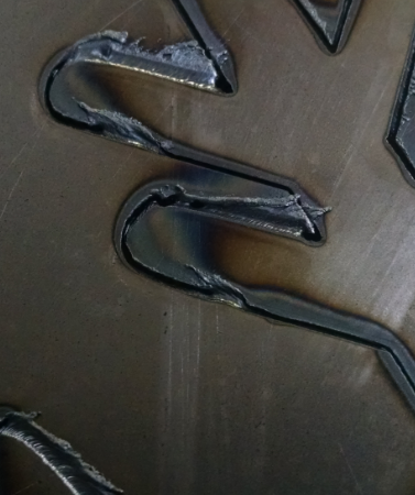
- Crashing Comes Easy
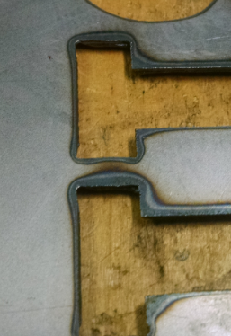
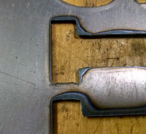
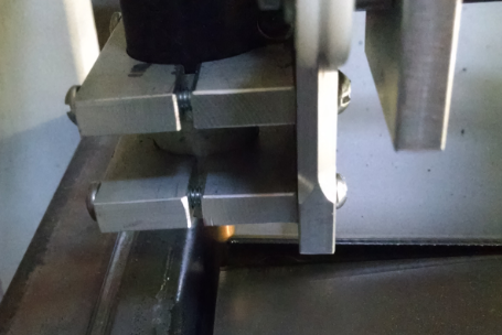
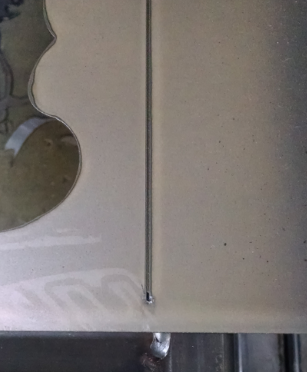
- Clean Cuts Come Hard
- Its been a while
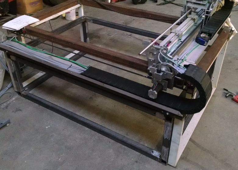
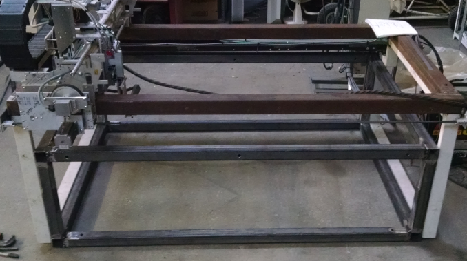
Phase I - Build a Plasma Table
Progress - Table is built and functioning. Hard limit randomly faults when enabled. Axis loses steps. GRBL/Universal GCode Sender appears to start/stop movement in a cut with multiple short line segments.
Controller - GRBL running on UNO
Interface - Universal GCode Sender running on Raspberry Pi
Mechanical - Many designs out there. Pick one and wing it.
Plasma Cutter - Use one on hand. PakMaster
Phase II - Build Material Rack
1-29-20 update. This has been put on back burner.
Progress - Not Started. Main rack being built with loader/unloader in mind. Not developed, trying to keep open build concept.
Mechanical - Stackable rack that is expandable to hold more sizes of to hold multiple sheets of material. Design for 4'x8' 4'x10' sheets. Allow to be expand to multiple sheet size as needed.
Phase III - Build Material loader/unloader
1-29-20 update. As much as I would like this to become part of the setup, space has become an issue and this is on the back burner until room is available again.
Progress - Not Started. Building main table that will have expansion/modification ability as the project evolves.
Controller - Use the Raspberry Pi IO or capable of interfacing with the Raspberry Pi.
Mechanical - Be able to slide material out from rack, lower raise material to plasma table height, slide under plasma table. Reverse order for uncut material unload. Finished parts will fall down when trap door under plasma table hinges downward. The finished cut *should* drop down if fully cut. Then the uncut material, if completely exhausted, will be cut from the main sheet. Trap door to drop exhausted material down same path as finished part.
Phase IV - Develop/Find network capable "cutting" queue to send file from office computer to plasma table.
Progress - Not Started


 dekutree64
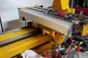
 Alastair Young
 Greg Duckworth
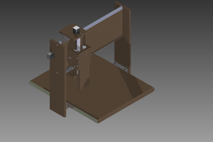
 Steel_9
Nice Build! Seeing this project reminds me of the CNC plasma cutter that I started on. I got the carriages designed and built before realizing that I had no space in my shop to put the finished unit.