Close
0%
0%

The Wireless Tin Can Telephone

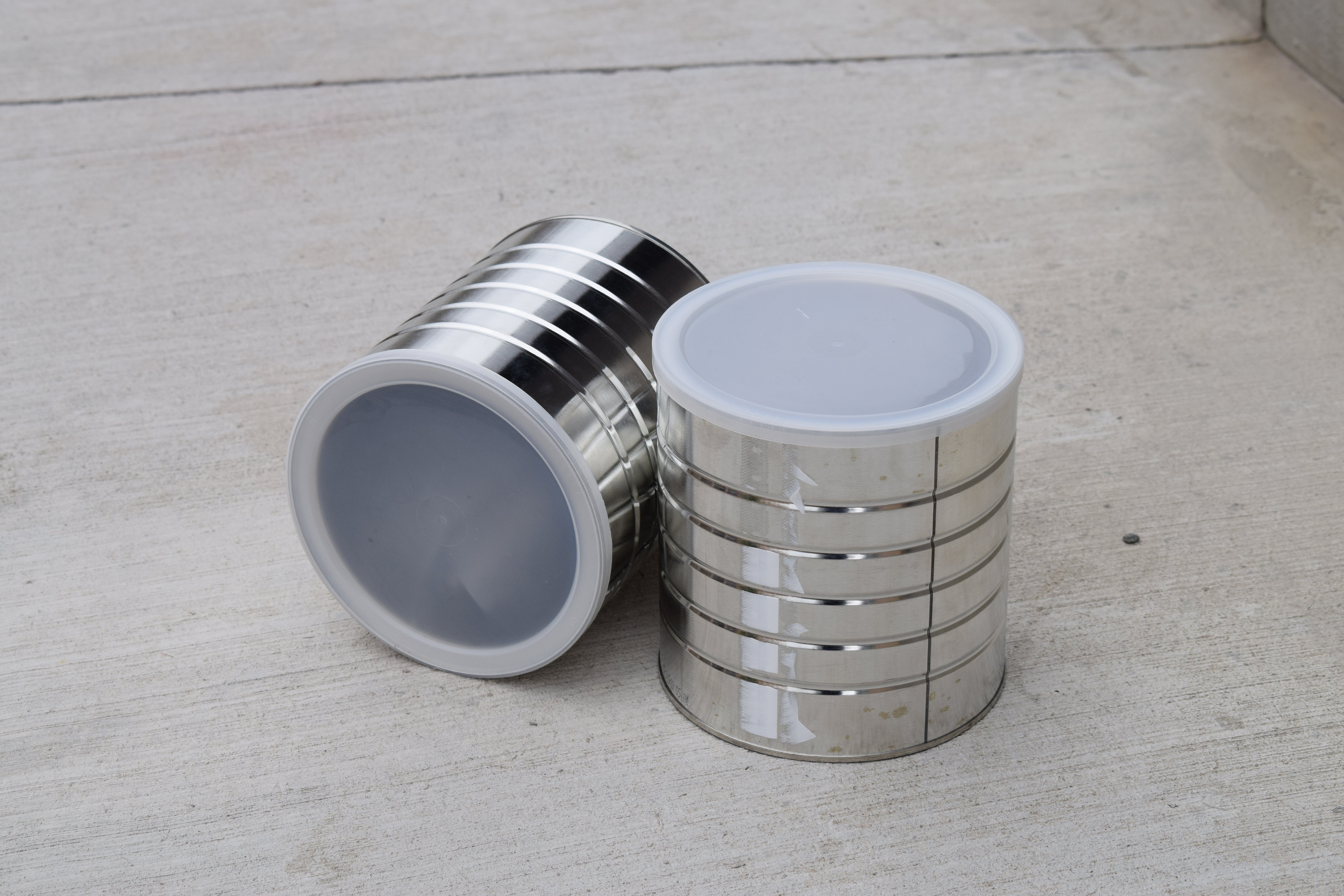
A new spin on an old toy, the wireless tin can telephone takes the technology of yesteryear and thrusts it into modern day!

Public Chat
Similar projects worth following
I made this project with the goal of giving kids a super easy, solder free, introduction to hobby electronics. That being said, all ages can enjoy building this project! There's something to be learned for everyone. From the NRF24L01 radio antenna, to the Arduino UNO, this project is packed with information about audio transmission. If this sounds like something you want to build, I've created both an entertaining video, as well as an educational Instructable to help you learn more about the project.

On the technical side, this project is a bare-bones Arduino Walkie-Talkie. It's based around two way radio, and it uses the NRF24L01 Radio Module to transmit and receive information. The radio module should allow for communication up to 1km, provided there is nothing blocking the signal. The code runs off of the RF24Audio Library, which makes it a super simple program. Great for those not software inclined. ;) The whole project costs around 75$ to make, depending on where you get your parts, and it takes about 3 hours to build. 

WalkieTalkieCode.ino

ino - 2.10 kB - 05/31/2020 at 03:50

Download

TinCanTelephoneThumbJPG.jpg

JPEG Image - 949.11 kB - 05/31/2020 at 02:25

Preview

Wiring Diagram.png

Portable Network Graphics (PNG) - 1.16 MB - 05/31/2020 at 02:25

Preview

Hole1.png

Portable Network Graphics (PNG) - 322.10 kB - 05/31/2020 at 02:24

Preview

Hole2.png

Portable Network Graphics (PNG) - 353.62 kB - 05/31/2020 at 02:24

Preview

View all 7 files

  • 2 × Arduino Uno
  • 2 × Gravity: IO Expansion Shield
  • 2 × Gravity: Analog Audio Sensor
  • 2 × AMP386 Audio Amplifier
  • 2 × 6xAA Battery Pack w/ Barrel Jack Connector

View all 8 components

  • 1
    Introduction

    Just the other day, I was in the middle of a very important phone call when my banana phone stopped working! I was so frustrated. That’s the last time I miss a call because of that stupid phone! (In hindsight, I may have gotten a little too angry in the moment, see pics)

    It was time for an upgrade. Enter the wireless tin-can telephone! The all new and improved gag phone, for all my fake communication needs!

    Note: (This project does actually work)

    Here’s how I built it!

  • 2
    Tools and Materials

    For this project, you’re going to need quite a few electronics, and a couple tools.

    I'd like to disclose that this project was sponsored by DFRobot. All of the parts were provided by them, and some of the links provided are affiliate links to DFRobot. Feel free to use them if you would like to support Facio Ergo Sum! Off-brand parts work as well. Thanks to DFRobot for making this project possible!

    Tools -

    • Drill (w/ Bits)
    • Tin Snips
    • Hot Glue Gun (Careful: Very Hot)
    • Needle Nose Pliers
    • Ball-peen Hammer

    Materials - (Two of all of These)

  • 3
    Prepping the Cans

    Before we can wire up the electronics, we’ll need to prep the cans. To do this, we will be drilling two holes, one for the antenna, and one for the button.

    I started with the antenna hole. First, I placed the antenna board inside the tin can, to measure how far from the side the hole would need to be. Then, using my finger to note the ridge, I marked the hole with an Whiteboard marker, so that I could wipe them off later. Then, using a tap, I put a small indentation where I was going to drill. This will help guide the drill in the next step.

    Depending on the antenna you use, you may need a smaller/larger hole. So what I did to find the right size, was compared the threads on the antenna to the drill bit sizes.

    Note: (Mine ended up being 7/32)

    Alright, SAFETY GLASSES ON!

    Once you’ve picked a size and marked out the hole, drill into the can, go at a high speed, but don’t push too hard. Because of how flimsy the tin can is, it will usually shear, so watch for sharp metal. Use tins nips and pliers to clean up this edge.

    Then it’s time for the button hole. This one’s a little different.

    Note: I’m working with what I have, so I decided to attempt it using the drill and tin-snips again. A Forstner bit might work much better. Here’s how I did it.

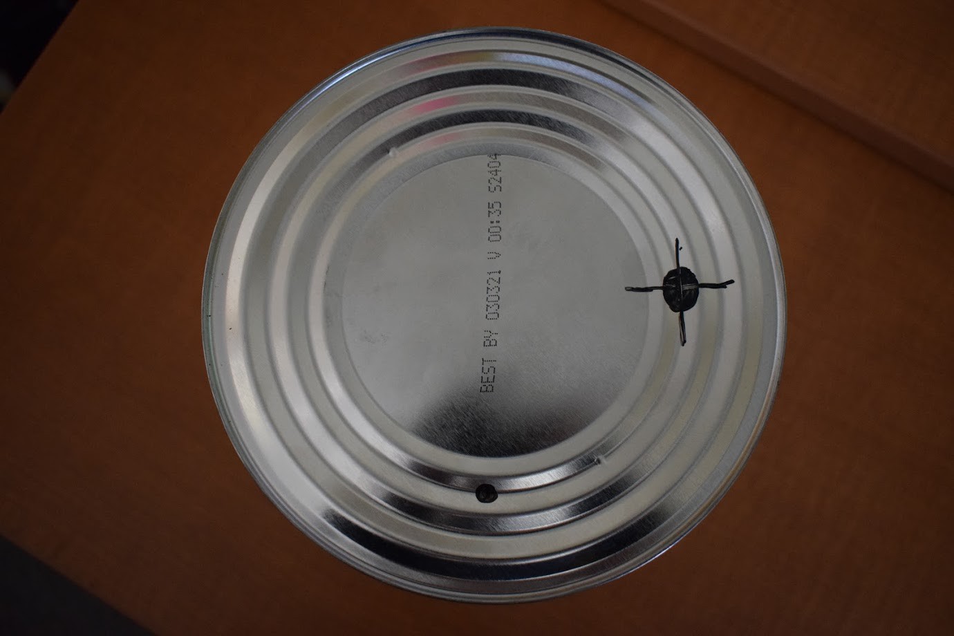
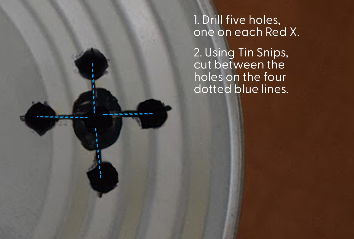
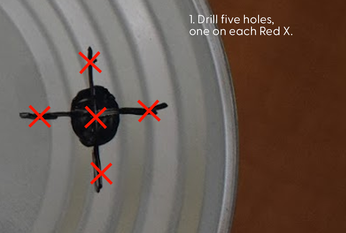
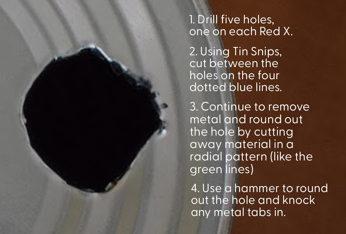
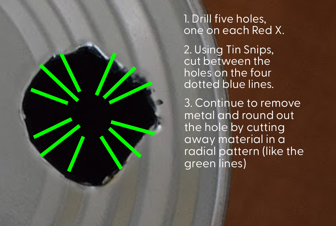
    First, I unscrewed the plastic “nut” from the button. Then I placed the nut onto the location I wanted the hole, and marked the inside diameter. Then I drilled five holes, and used tin snips to clean the material out and form it into a circle. Mark the hole, tap it, and drill.

    STOP! It's HAMMERTIME!

    After this, I used a hammer and pliers to knock in the metal tabs and bend them down. Please refer to the images for a better idea of how I did this. I’ve provided a series of shoddy diagrams that should be able to help you out:

    Note: I suggest using a ball-peen hammer. I used a regular hammer because that’s all I had.

    Once that’s done, you can screw in the antenna and the button. Again, be careful of any sharp metal bits!

View all 8 instructions

Enjoy this project?

Share

Discussions

Jon wrote 09/02/2020 at 20:56 point

I can see how your board placement contributed to the selected antenna placement but rev 1.1 definitely has to put the whip straight in the middle and paints it white (because it's a string, get it?). Heck get even sillier and get something like a braided cotton rope that you can snug down to the base of the antenna and let dangle off the end to really sell the whole "I am having way too much fun with this"!

  Are you sure? yes | no

Similar Projects

Does this project spark your interest?

Become a member to follow this project and never miss any updates