Nick Sayer
The XMega32E5 doesn't map perfectly to the Mega328, so we're going to have to take some liberties with the pin mappings.
Instead of having a separate AREF pin for the ADC, the XMega32E5 shares this function with A0. So in this design, A0 is connected to the AREF shield pin, and A1-A6 are mapped to the UNO shield's A0-A5 pins. A7 is connected directly to an on-board LED (on the Uno, this was traditionally D13).
Port C is wired to D0-D7 on the Uno, and port D0-D5 continue as D8-D13. D6 and D7 are wired directly to the UART chip's serial I/O. The serial boot loader will be configured to move the USARTD0 pins to their alternate mapping at the top of port D, aligning the TX and RX pins with the on-board USB UART. This will allow USARTD0 to be dedicated to boot loader and console activities within the Arduino IDE.
Port R will be connected to a 16 MHz crystal, and the boot loader will be configured to use this crystal and the internal PLL to generate the 32 MHz system clock.
On the XMega32E5, the TWI pins are on port C rather than port A, so the extra i2c bus pins on the Uno layout will be rededicated to PDIC and PDID. There will also be a traditional pinout PDI port on the board useful for the initial loading of the serial boot loader.
Power will be supplied solely over USB. Alternatively, the user can supply 5 volt power on the +5 Uno pin. An on-board LDO will make 3.3 volts from the 5 volt supply.
The USB data pins will go to a USB UART chip. In addition to the aforementioned serial connection, the DTR pin will be capacitively coupled to the PDIC/!RESET pin so that the IDE can force the chip to reset, activating the boot loader.
 Lithium ION
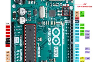
 Shahbaz
 ar3itrary