 Subhajit
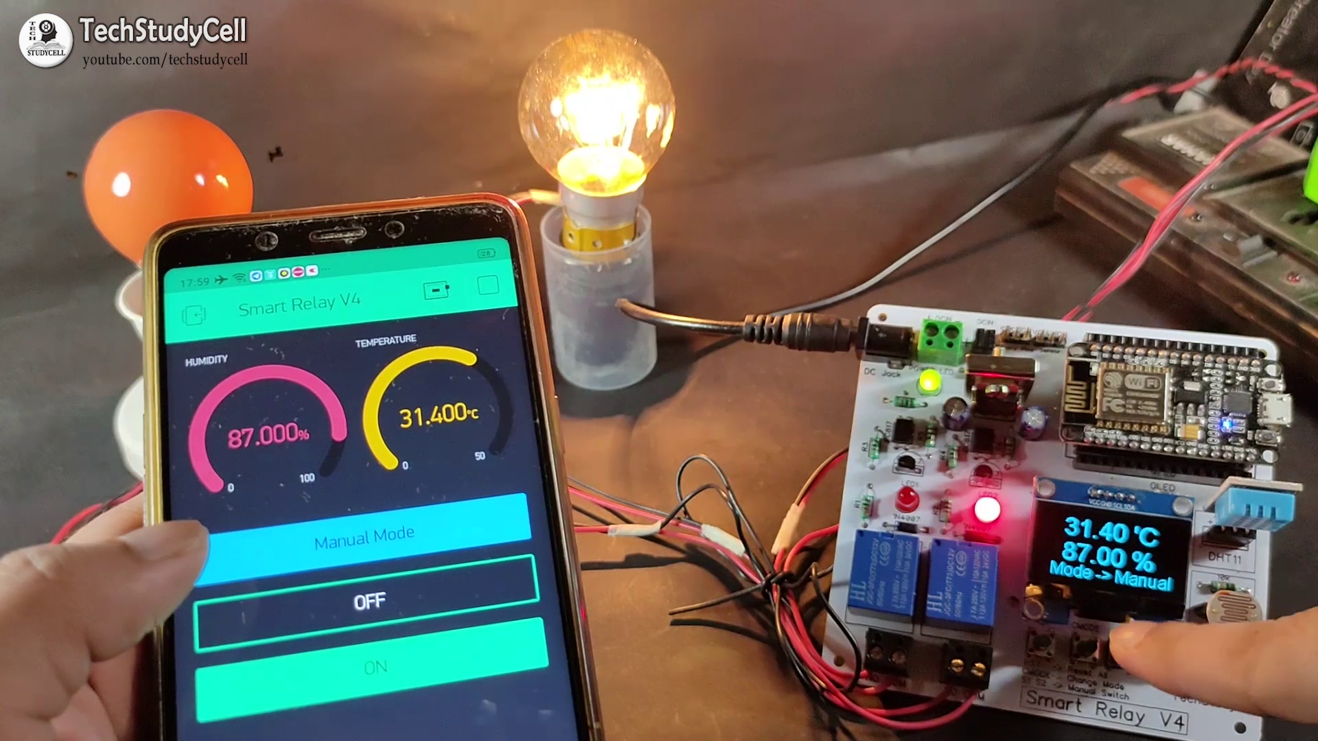
This smart home project has the following features:
1. Home appliances controlled from Mobile using Blynk App
2. Home appliances controlled by temperature & Humidity sensor automatically (In Auto Mode)
3. Home appliances controlled by Dark Sensor automatically (In Auto Mode)
4. Monitor LIVE room temperature & Humidity reading on OLED and Smartphone
5. Home appliances controlled with manual switches
6. Control Home appliances through the Internet.
I have explained all the details in this tutorial video.
SUBSCRIBE our YouTube channel for more such projects:
https://www.youtube.com/c/techstudycell?sub_confirmation=1
Required Components for this Smart House project
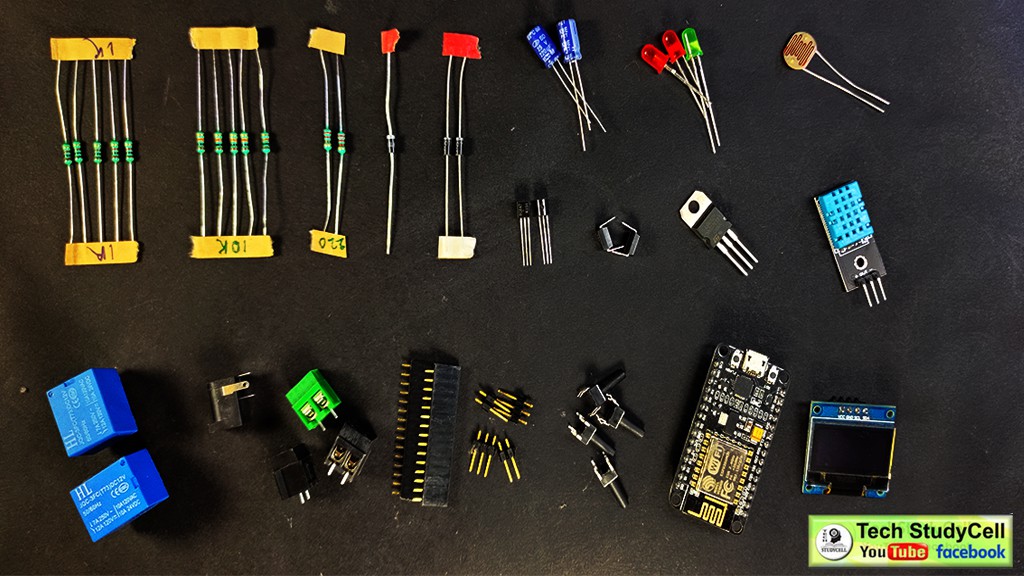
1. NodeMCU
2. DH11 Sensor
3. LDR
4. 10k Resistors 5 no
5. 1k Resistors 5 no (R1 to R4)
6. 220-ohm Resistors 2 no (R5 & R6)
7. Optocoupler PC817 2 no
8. BC547 NPN Transistors 2 no
9. Diode 1N4007 2 no
10. Diode 1N4001 1no
11. LED (1.5v) 3 no
12. Capacitors 100uF 2 no
13. SPDT 12V Relays 2 no
14. 7805 voltage regulator 1 no
15. Push Switch/ button 4 no
16. Connectors & jumpers
17. OLED I2C Display (0.96" or 1.3")
Step 1: Circuit Diagram
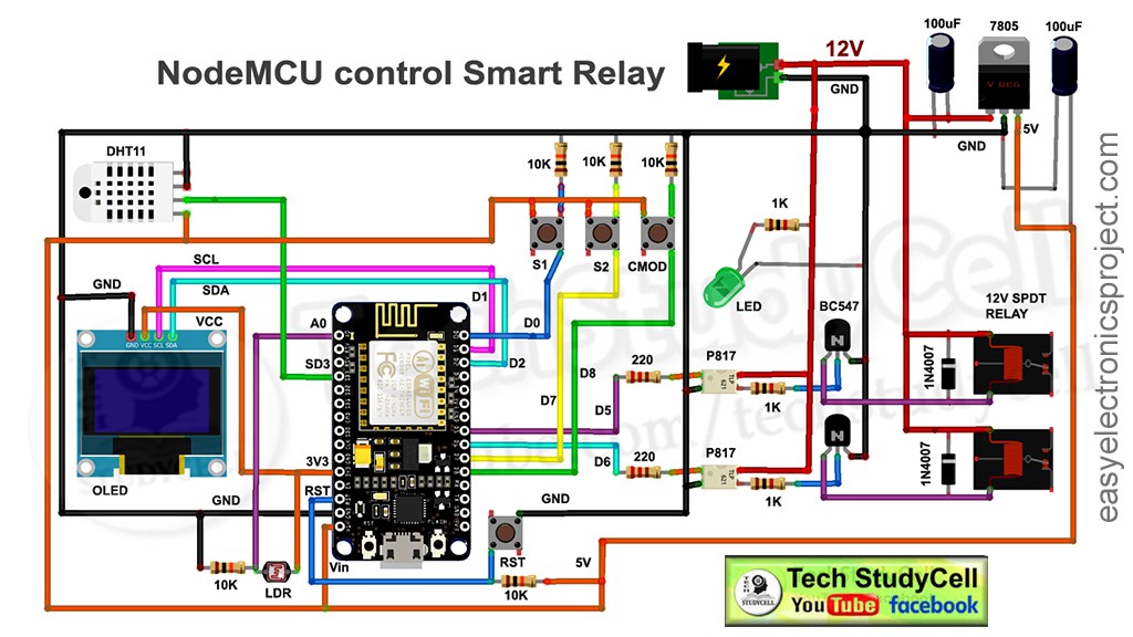
This is the complete circuit diagram for this IoT based home automation project.
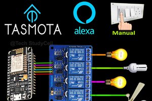
I have used NodeMCU to control the relay module. I have connected the DHT11 temperature & humidity sensor and LDR to control the relay automatically according to the room temperature and ambient light.
There four pushbuttons connected with NodeMCU i.e, S1, S2, CMODE, RST.
S1 & S2 to control the relay module manually
CMODE to change the Mode (Manual Mode, Auto Mode)
RST to reset the NodeMCU
I have supplied 12V to the relay module and used a 7805 voltage regulator to supply 5v to NodeMCU.
Step 2: Make the Circuit on Breadboard for Testing
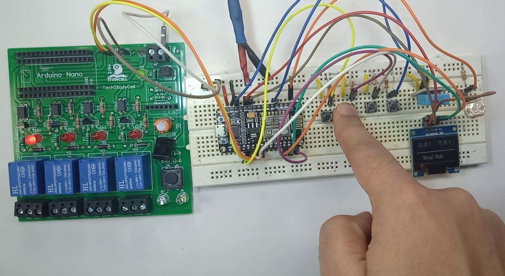
Before designing the PCB, first I have made the circuit on the breadboard for testing. During testing, I have uploaded the code to the NodeMCU then tried to control the relays with the pushbuttons, Blynk App, temperature sensor, and LDR.
Download the Code for this NodeMCU project
https://drive.google.com/uc?export=download&id=1jYhJC-CUVciWLWlL0Dc36pofpojKfqp-
Step 3: Install the Blynk App
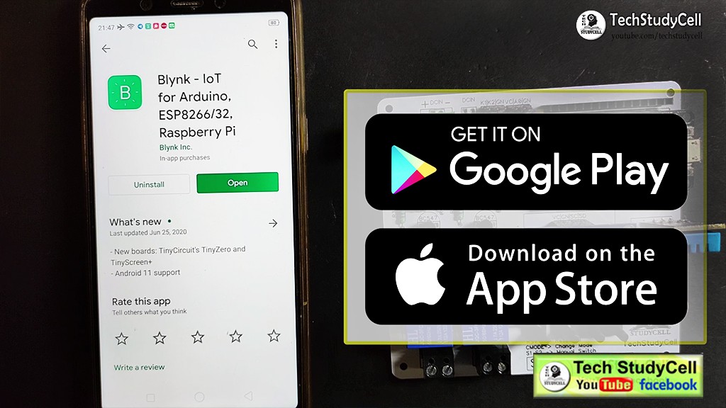
Install the Blynk App from Google play store or App store then add all the required widgets to control the relay module and monitor the temperature and humidity. I have explained all the details in the tutorial video.
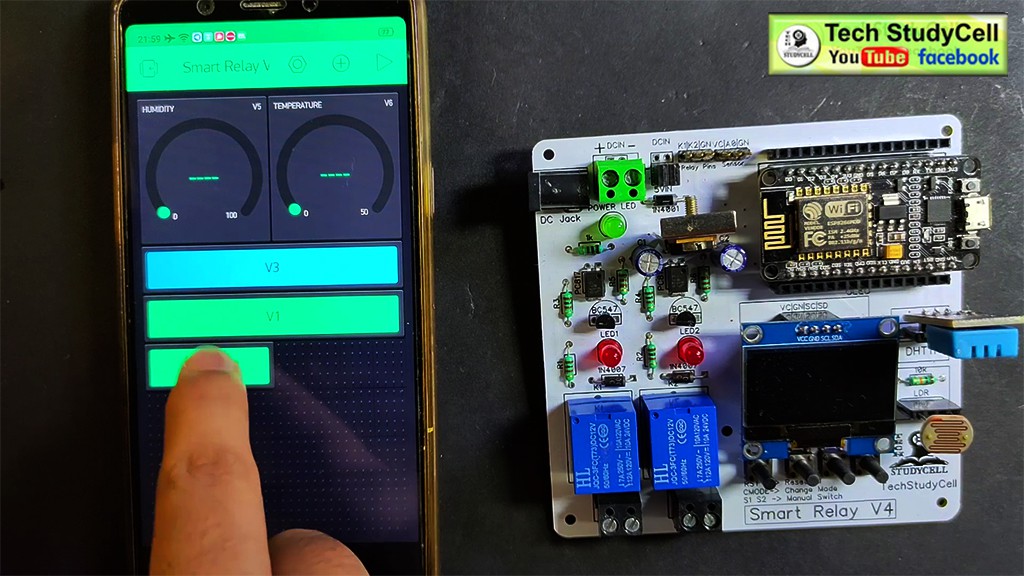
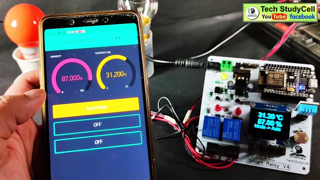
I have used the 3 button widgets to control the relay module and change the mode. And 2 gauge widgets to monitor the temperature and humidity.
Step 4: Different Mode of the Smart Relay Module
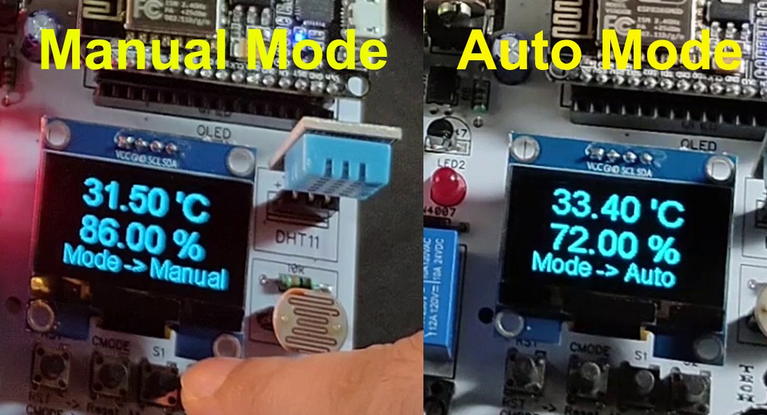
We can control the smart relay in 2 modes:
1. Manual Mode
2. Auto Mode
We can easily change the mode with the CMODE button fitted on the PCB or from the Blynk App.
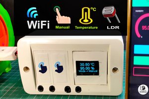
Step 5: Manual Mode:
In the Manual mode, we can control the relay module from the S1 & S2 push-buttons or from the Blynk App.
We can always monitor the real-time feedback status of the switches from the Blynk App.

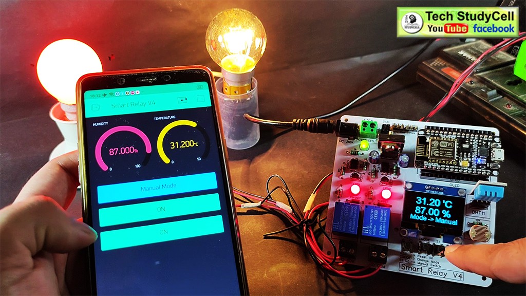
And we can also monitor the temperature and humidity reading on the OLED display and the Blynk App as you can see in the pictures.
With the Blynk App, we can control the relay module from anywhere if we have the internet on our smartphone.
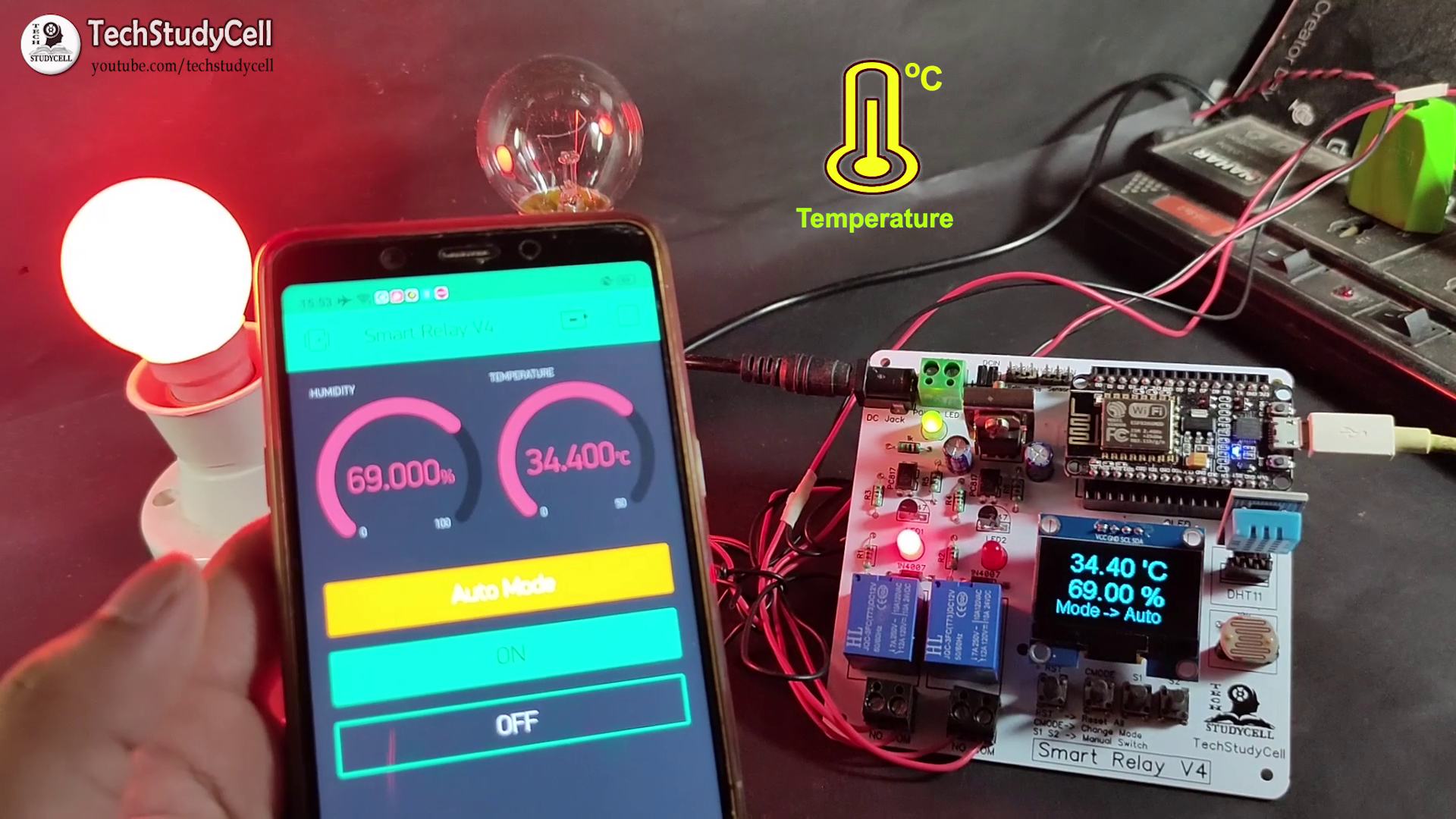
Step 6: Auto Mode:
In Auto mode, the relay module controlled by the DHT11 sensor and LDR.
We can set a predefined minimum and maximum temperature and light values.
In Auto mode when the room temperature crosses the predefined maximum temperature the relay 1 turns on and when the room temperature becomes lesser than the predefined minimum temperature the relay 1 turns off automatically.
In a similar way when the light level decreases the relay 2 turns on and when the light is sufficient the relay 2 turns off automatically.
I have explained in details in the tutorial video.

Hi Suhajit
Because I can’t download the information of your project, I like to DIY it at home. Can the relevant information of this project be sent to me by email? thank you very much! My email address: sengchuary@qq.com