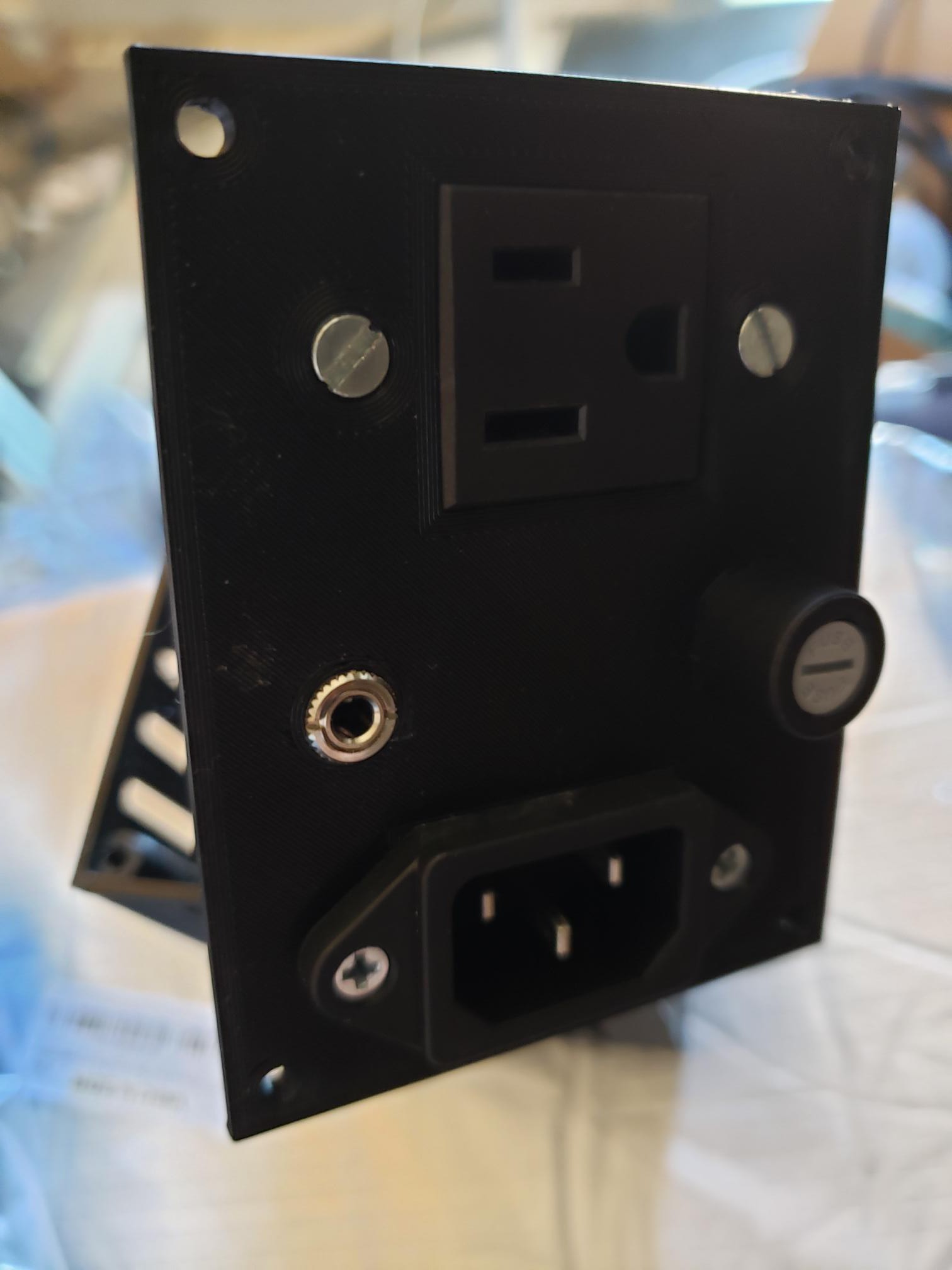
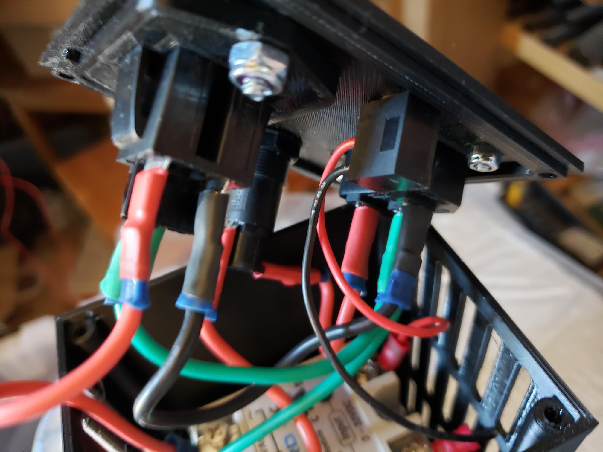
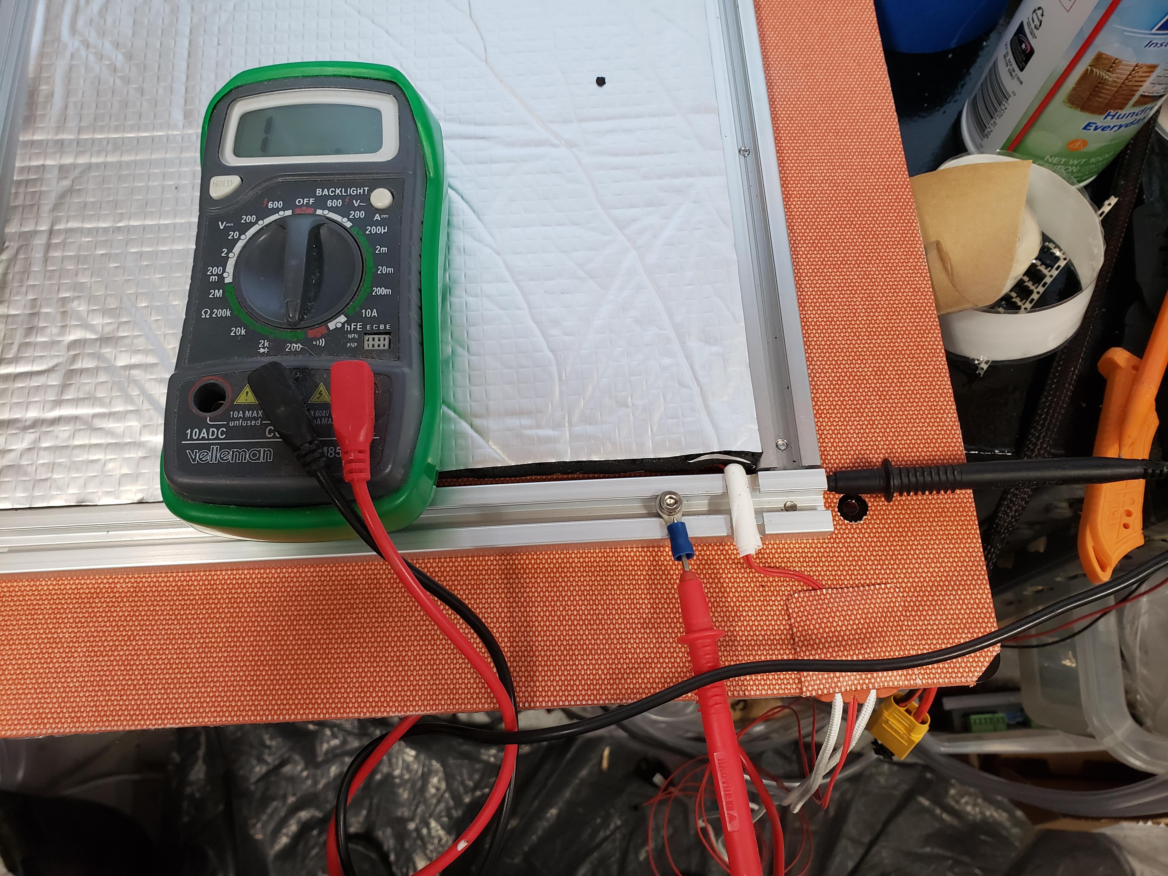
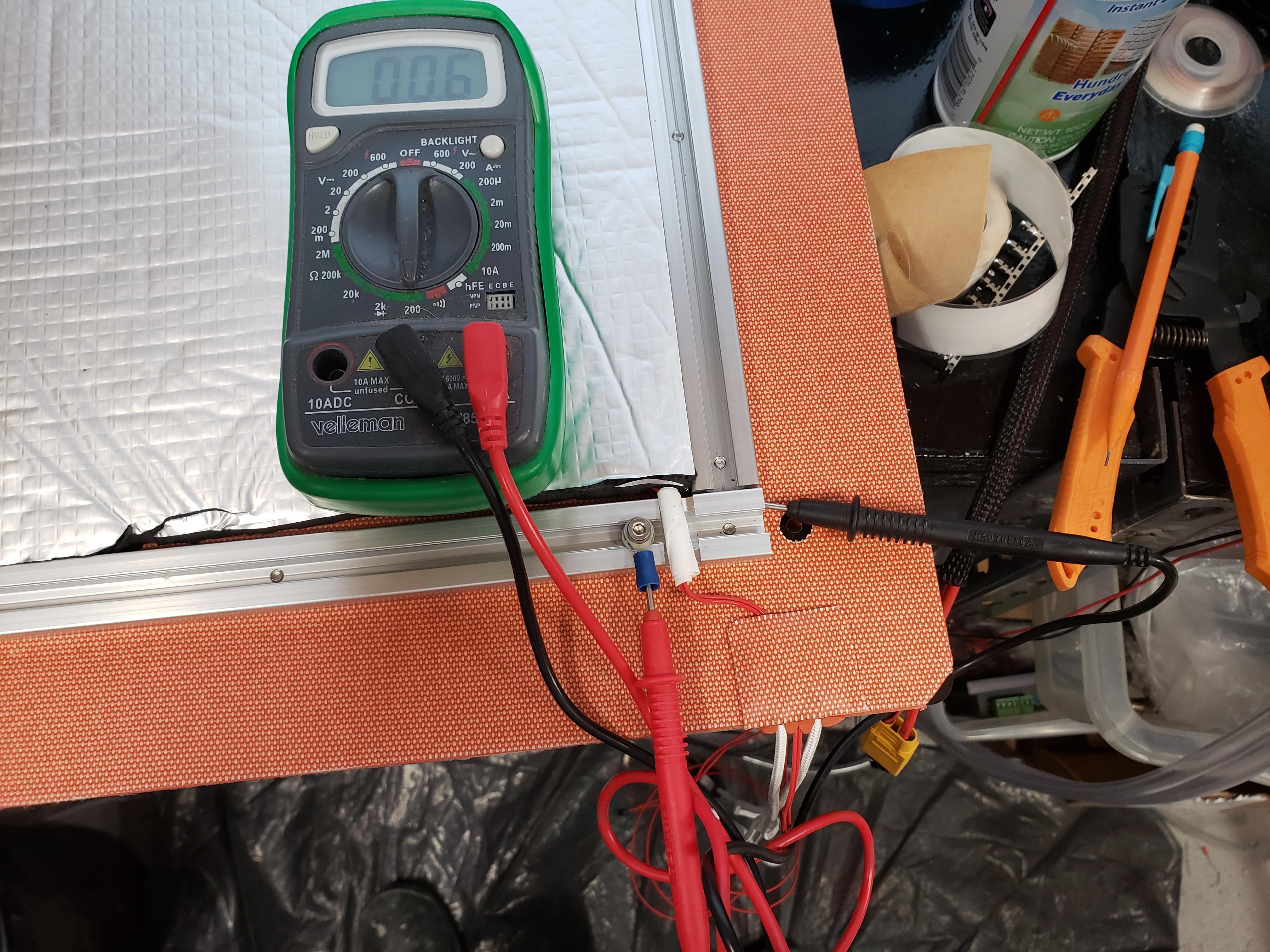
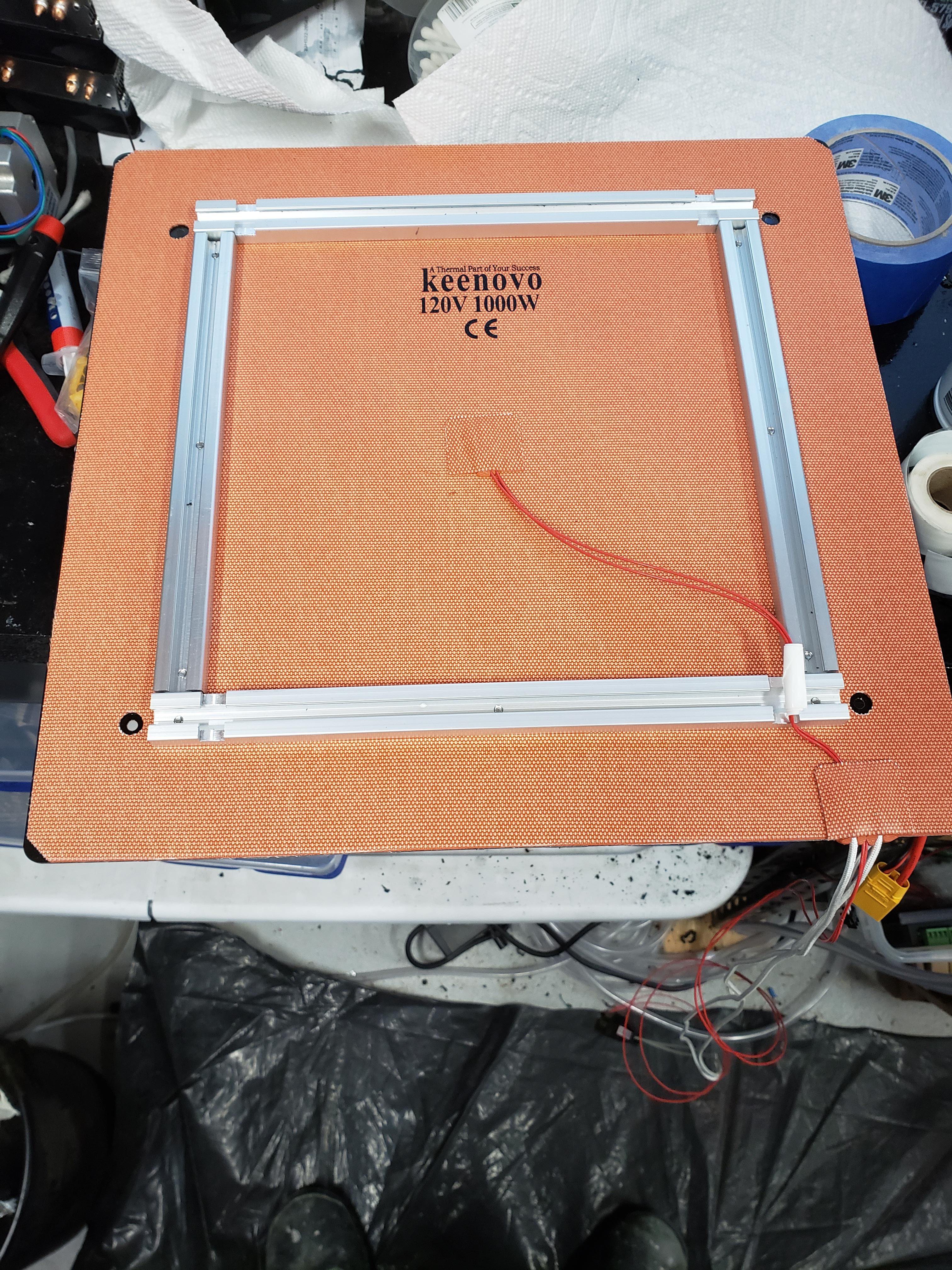
Using a stock Ender 5 Plus hotbed. Plus a Keenovo 1000W AC Silicone heater: https://keenovo.store/collections/custom-keenovo-silicone-heaters/products/keenovo-silicone-heater-370mm-x-375mm-for-ender-5-plus-3d-printer-build-plate-heatbed-heating-upgrade Remember the proper voltage for your location. Plus an SSR(generic 40A with Heatsink)
0%
0%
Ender 5 Plus Hotbed Upgrade
Upgrading the Ender 5 Plus to a 1000W AC Silicone Heater
Become a Hackaday.io member
Already have an account? Log in.
Just one more thing
To make the experience fit your profile, pick a username and tell us what interests you.
Pick an awesome username
hackaday.io/
Your profile's URL: hackaday.io/username. Max 25 alphanumeric characters.
Pick a few interests
Projects that share your interests
People that share your interests


 Steve Hernandez
 Michael Perrone
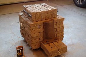
 Matt Moses
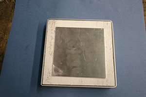
 Christoph