0%
0%
Seven Segment Display with Arduino and 74HC595
Control a Seven Segment Display using just 3 pins of your Arduino, This technique is possible because of 74HC595 a.k.a. a shift register.
Become a Hackaday.io member
Already have an account? Log in.
Just one more thing
To make the experience fit your profile, pick a username and tell us what interests you.
Pick an awesome username
hackaday.io/
Your profile's URL: hackaday.io/username. Max 25 alphanumeric characters.
Pick a few interests
Projects that share your interests
People that share your interests


 Clovis Fritzen
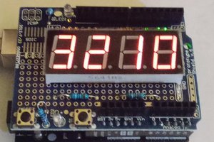
 Dan
Dan
 electronicsworkshops