 Paul McClay
Ok, it looks like I can take another swing at this.
New motors were waiting in the mailbox when I got back here. After swapping out the crippled motor the revised machine cut a test pocket like it was supposed to a month ago. Yay. Onward.
But first:
(or just skip to the next entry)
That Day of Fail
tl;dr: I got get-there-itus and tried to grab the ring when I should have taken a day off.
Retrospectively sorting out a timeline of the unrequited sprint of early September reminded me how poorly (my) memory works for some things, and thus the value of notes and pics/vids/files with timestamps. One day in particular I wanted to review to have a history of many loose ends that feel like the sort of thing that I'll wish I had a better history of when they turn up again later.
Just about a month ago I logged that I had:
- CADed, cut, built & tested another rev of the axes, that
- [good things]
- roughs out my test pocket encouragingly well, but with a new imperfection that i don't understand
- has died, in three different ways, at about the same point in the first finishing pass of same test pocket
What that looks like:

After redesigning the XY table as described under the Direction header in the same log entry and adding a Z axis of similar design, I tried cutting the usual test pocket. In addition to validating the revised design, because of course it would just work, this would test conventional milling with no extra mass on the X & Y leadscrews for the first time since climb milling lost _the_chatter_wars_.
For all three tries the roughing operation completed without difficulty. I had inserted a pause in the gcode at this point to get a look. Here's the first try below. It looked ok but not great:
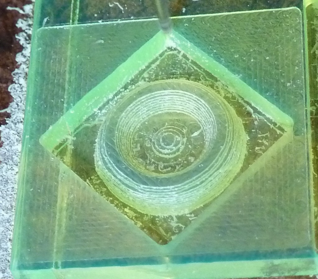
Because this version of the XY table uses less material and may be less stiff, the merely "ok" output didn't throw me too hard. But some of it was weird. Ungreat features included:
- Variation in quality of the four vertical walls of the pocket. Although something of a regression, that's nothing new. I didn't try very hard to interpret that at the time -- and I still haven't worked out how the differences around the four sides correlate with various mechanical imperfections. Mystery.
- 2nd try: worse but not awful
- 3rd try: pretty good
- The outside surface of the round feature has -- this is hard to describe and barely visible above but shows better in the next photo below -- a patch near the pocket wall in each quadrant that looks depressed or offset inward from the intended surface. I still have no idea what caused that. It's unlike some earlier tries where excessive runout punched out the pocket wall instead of punching in the side of the ring. Mystery.
- 2nd & 3rd about the same
- A conspicuous ring of too much horizontal offset around the outside of the round part between the 3rd and 4th slices. I think it looks like the 3rd slice was cut too small. No idea how so. Mystery.
- 2nd: same but less so
- 3rd: none
Once resumed, the first attempt continued with the constant-X parallel finish profiles. About 3/4 of that appeared to run ok. Then the X axis stopped feeding and the machine cut progressively smaller profiles in the same spot, cutting into the part. Bah. Stop job. That's the first/left fail shown in the triptych above. Right after that the X axis didn't respond to movement commands. Then in a short time it fixed itself. Ok. But why did it die and how to not repeat that?
I guessed something like this:
- Steppers heat up more when holding position than when running. At least in my experience (this will come up again...)
- The X motor mostly holds position(s) through the X finish operation
- So the X motor temperature rose through that operation
- Rising temperature increased copper winding resistance
- Constant-current stepper driver increased voltage (pulse width) to maintain current
- Crappy wall-wart power supply -- grabbed for first tests and not reconsidered since -- couldn't push enough Vs and Is to turn the hot motor...
- ...until it cooled and resistance came back down.
Why had that become a problem when it wasn't before? Well, even as first starting to poke at this that day I half thought a wiser me would take the day off. I think it maybe went something like this: I recognized need for an appropriate power supply in any case. Presumably the motor driver current limit doesn't depend on supply voltage so a few more Vs should do no harm. And the current limits were moderate for the motors, relative to a still-unverified guess at what they can handle. So I swapped the lame supply for a laptop power brick with a few more Vs and lots more Is of finest quality. Immediately the motors sounded more authoritative in all motions, so clearly I'd kept the first supply far beyond what it was good for. I suppose that was such a clearly good thing that I just forgot any questions of why the first supply couldn't keep up where it had managed before and whether my rising-R conjecture fit reality or not. I think I at least checked the motor driver current reference voltages to make sure they were as expected. At some point I dialed them all down a little, but I don't remember when I did which ones. Maybe I reduced X&Y at this point or maybe later.
Then there's the first 3/4 of that pass that appeared to run ok. But more mysteries.

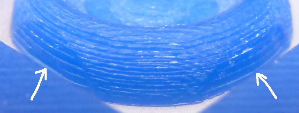
From the bottom up in this photo, the first ~2mm of profiles look ok -- where they actually touch the part. This view shows the two (of four) recessed patches in the waterlines in the SE & SW quadrants of this view. They appear set back from the rest of the surface but follow the expected curvature. The X profiles pass right over without engaging them (except for the couple that do...).
Here's another look at that - from the (good side of) the last try of the day:
But back to the yellow part and it's profiles:
After the first ~2mm, a couple of profiles gouge deeper. At first glance that looks like the Z axis dropped a bit. But the ends of the profile arcs do not gouge below the pocket floor, and the profiles look perfectly normal where they dip down inside the bowl-ish area (not clear in the photo). ... Mystery.
Then the next 60ish profiles look fine. Almost. From the right angle. But the (yellow) photo above shows the profiles running smoothly along the outside of the left side of the figure and the inside of the right side, while not touching the inside of the left side or outside of the right side. It looks like possibly a small shift of the Y axis. But there is a continuous arc of marks where the cutter touched the pocket floor around the left side of the figure and much less so around the right side -- showing that the profiles are not simply shifted to the right but that the right side didn't come down to the same Z level. But it wasn't simple backlash/hysteresis because the profiles were cut boustrophedonically[1]. And it wasn't a tilt (roll) of the workpiece while paused because the apparent Z deviation alternates up and down across the piece. It looks like the Z deviation varies with the surface slope but I haven't much considered how that would happen. Mystery.
So went the first try.
That would have been a good time to answer some questions rather than blunder ahead.
At some point between switching power supplies and running the second try -- I think while first testing axis motions with the better power supply -- I tried the Z axis without hanging the counterweight (more brain fry) and it lifted the ~0.5kg spindle -- imperfectly but more than not at all. !. I thought that was pretty cool, hung the counterweight and carried on. I did not connect the dots all the way to "that's a lot more juice than this really needs".
And that bit of frybrainfail would soon emerge as the major cost of not taking the day off.
Second try. Because of course it would just work this time.
The rough/waterline operation ran ok. The resulting pocket had rougher walls but less discontinuity between waterlines around the outside of the round bit.
For another oddity: the face cut was super clean -- the best so far I think. Mystery of another kind.
The X finish pass ran normally to about ~60%. "Fixed" I was thinking... Until the Z axis stopped lifting before it stopped driving down into the part. Bah. Stop job.
The Z motor/leadscrew was locked up solid. That couldn't be good...
Removing the spring plate on the back of the motor to get at the rotor/screw revealed this:

The white part locates the bearing for this end of the rotor/screw. It obviously got hot enough to flow and, apparently, cease to support the bearing.
Normally this part, the bearing, and the rotor/screw slide out when exposed like this. In this case the screw wouldn't budge with as much force as I felt like pushing on the plastic slider containing the lead screw nut. That melty bit had apparently melted itself into place there.
However, while trying to shove it out of there something "broke" and that part shifted a tiny bit. That freed up the rotor. Although still captive, the screw then turned freely. Maybe it wasn't so bad...
But it felt less "coggy", like the magnets got their curies cooked. So it wasn't very good...
But it wasn't entirely broken. Sometimes it worked, if relatively weakened, but sometimes not. I spent a good deal more time with that than an outright failure would have absorbed.
One of the coils had become intermittent. Strangely, the coil resistance wasn't too far off: ~12Ω vs ~15Ω. Like maybe a couple of turns had shorted across ~20% of the coil. But energizing the coil produced no discernible magnetic effect. Unless I fiddled with it for a while then it would start working. Weakly but with enough torque to seem usable. Until it stopped working. Unless I fiddled with it for a while...
Eventually it became evident that the intermittent coil worked when hot enough. While fiddling with it the working coil was heating the intermittent coil until it closed or opened whatever fault broke it. Then I'd think it worked well enough to maybe work and put it down -- so it would cool off and not work the next time I tried it.
So the motor needed to be hot enough but not too hot. Great.
To heat the motor and keep it hot, I disabled Grbl's idle function. That worked well enough to seem like a reason to try again.
I should clarify that "hot" means warm here.
Somewhere in there I turned down the Z current to at least reduce likelihood of recurrence.
(With self-locking leadscrews, it's ok to let Grbl de-power the motors when not actively stepping.)
Ok, but...
My conjecture from the first try was that the X motor got hot while mostly holding still after working for a while. Now the Z motor has clearly cooked itself while working after intermittently holding still for a while. What's up with that? I wondered if greater friction heating due to heavier load might have contributed, but I expect the axial force went to the other end of the screw - unless I misplaced the counterweight to lift hard but I don't think that happened. Steppers usually heat up more when holding still, presumably because back emf reduces current when the motor spins. IME this happens with "constant current" drivers too, which I've chalked up to high(ish) frequency switching effects without understanding. This will be well known to people who know electric motors but not to me: if increasing load while spinning reduces back emf increasing current - is there a max load condition where a stepper heats more than while holding position? Like, because there is actual work happening ... and heating bearings or something?
An idea while writing that: once I eventually busted the melted bit loose and got a look at the rotor, it was apparent that it had rubbed the stator for a while before seizing. If the axial load forced the screw toward the other end bearing away from the spring in the motor end, then the motor end bearing preload would be at minimum and that end of the screw would be least resistant to radial displacement. I can't think of an inherent radial load, but there wouldn't be exactly zero radial force in a real device. Can the motor make enough torque to make significant heat from a rubbing rotor if something about the profiling operation pushed that end of the screw around more?
Also - for casually sticking to a screwdriver or whatever, the cooked rotor doesn't feel noticably weaker than a good rotor. I would have to compare more carefully to say there really isn't much difference. But I'll say there isn't a dramatic difference. Is the significant property something more local like sharper pole transitions or such? Does the failure have more to do with disadvantageously magnetising the stator? Did rubbing wear the rotor enough to significantly increase gap between the rotor and stator poles?
Mystery.
Anyhow...
The third try. The blue one.
I neglected to check the thickness of the slightly thinner material. The material thickness pretty much exactly matched the pocket depth (2.5mm). While the pocket floor skimmed the double-stick tape under the material, without marring the so-far-unspoiled spoil board, the tape still held the round center in place well enough for the X profile operation. For the half of it that happened, that is.
Again, the machine was running along looking fine. Until half way through the X profiles. Then the Z axis missed a few descending steps, leaving the bit cutting accurate-looking profiles in the air just above the intended surface. Bah. Stop job. Go to bed.
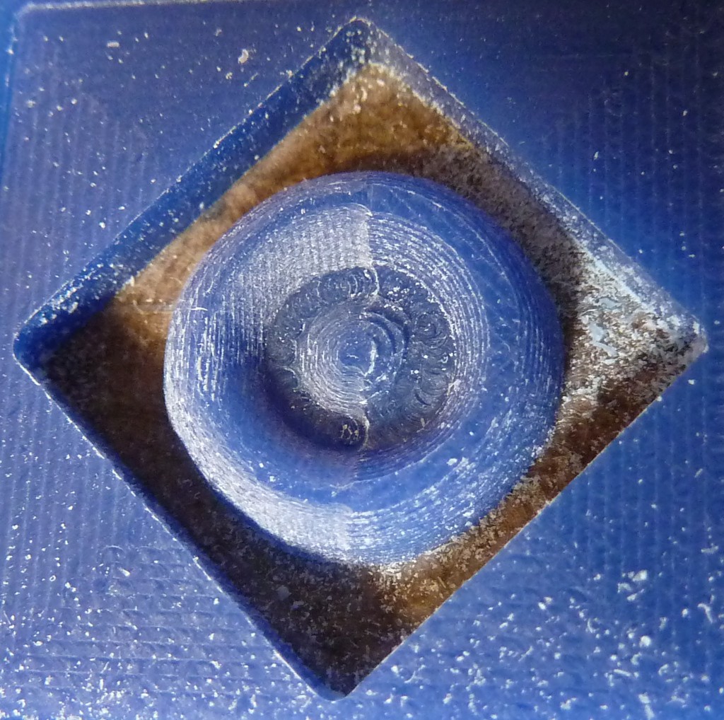
In the other photos above the center is pretty close but not perfectly positioned in the pocket. I put fresh (single sided) tape under the part to suspend the center in the center of the open square hole and eyeballed the center into place.
The first try maybe heated the X motor. The second try clearly heated the Z motor. I don't see indication of overheating the Z motor in the third try. Maybe it was just working on such a thin margin that it was bound to drop steps occasionally. Maybe the temperature sensitive intermittent had an upper limit also that wasn't very hot, and the motor was approaching that - but still the question of why it heated more while working profiles than while holding waterlines. Or did it cool down near to the low side of keeping the flaky coil working? And if so, back to the question of what cooked Z on the second try. I suppose the holding=hotter approximation will have proved inadequate before this is done.
Mystery.
And another little thing... exploring feed, speed and depth of cut remains a thing to do. When I first tried the first XY table under the Dremel-clone in a fixed stand, I tried a little deeper cut and it didn't go great. So trying to cut deeper hasn't been a front-of-mind thing.
That second fail cut a really deep slot (relative to project scale). A little rough but it kept moving. Hmm.
[1] bidirectionally. but a wonderfully less sterile word that seems worth rescuing from obscurity: boustrophedonic
If you watch a farmer ploughing a field, he cuts a furrow one way, then turns his tractor at the headland and ploughs the next furrow in the other direction. To cut all the furrows in one direction would require him to waste every alternate pass across the field. This has been obvious to farmers ever since they began tilling the land many millennia ago.
You can get some idea of how ancient the idea is from this word, which derives from the ancient Greek boustrophedon, literally “ox-turning” [...]
--Michael Quinion
Discussions
Become a Hackaday.io Member
Create an account to leave a comment. Already have an account? Log In.