 Paul McClay
-
OSHWA interview
10/13/2022 at 04:07 • 0 commentsOctober is Open Hardware Month -- an initiative of the Open Source Hardware Association. And OSHWA is starting a Monthly Talks series. And...
...I've just enjoyed the privilege of helping to kick off the series with some long answers for short questions and occasional handwaving. Thanks Lee & Sid for choosing this project to share!
Wow -- apparently I think with my eyeballs.
-
Z v3 survives slow learning -- and a bonfire of time
10/03/2022 at 20:37 • 2 commentsI considered giving up on this "better" vertical axis idea before figuring out that its problems were really just me.
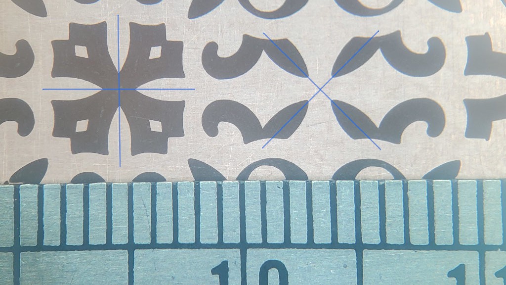
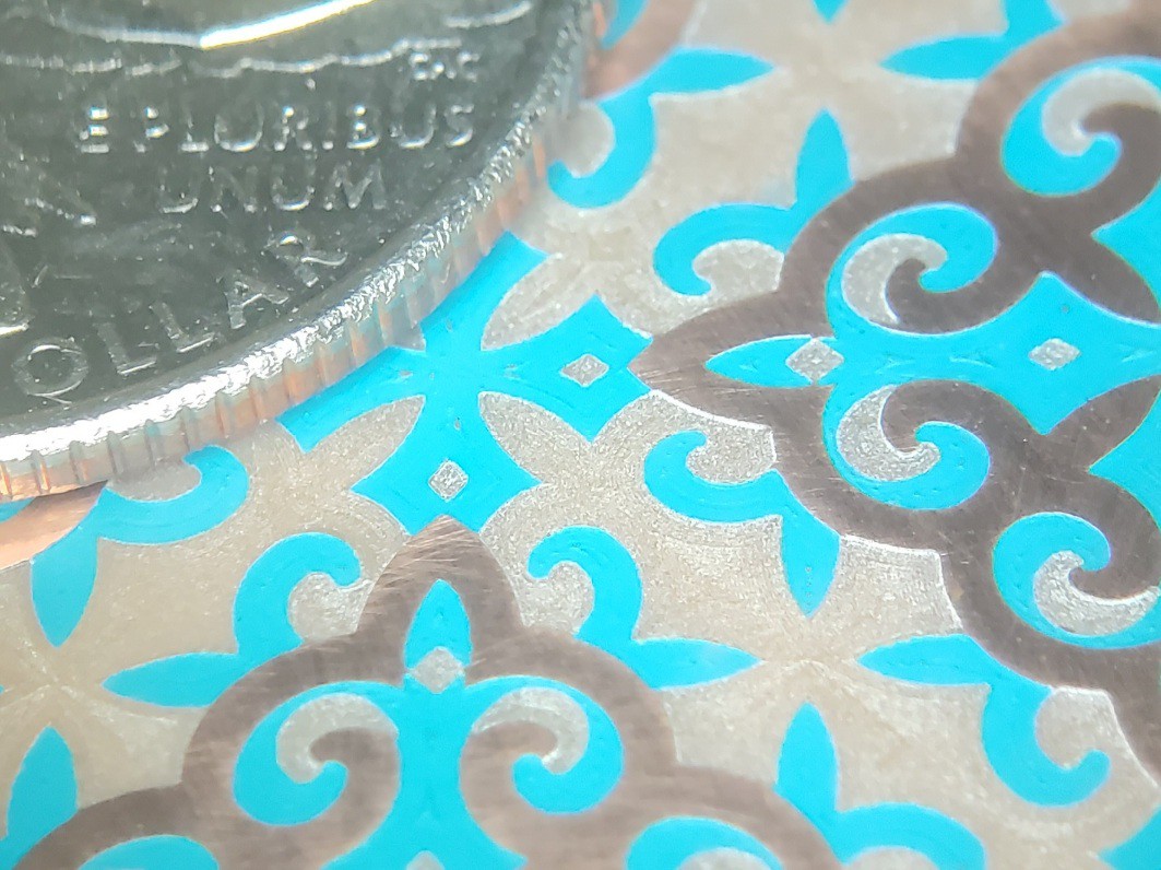
The pic shows a fragment of ornamental pattern milled from copper-clad board, and a mm rule. I like how the two sets of four points, in positive and negative space, look pretty close to symmetric and line up well.
![]()
That's encouraging because milling fine-pitch circuit board features is a target application and skimming a thin skin of copper from a surface that isn't flat tests the Z axis.
Six weeks of thrash for two lessons:
- Stepper heat changes tool tip to workpiece distance by more than the thickness of 1oz copper cladding -- slowly
- DIsconnect Z probe sense from conductive material before milling
Cleverly hidden among many words below is the lack of any more useful information that you would miss by not reading any further than right here ✾ about tedious circumambulations to nowhere other than discovery that they were somewhere between mostly and entirely unproductive apart from discovery of why so.
You can still bail out now.
Heat / Temperature / Dimension / Time
If you want to hit really precise Z levels with really tight repeatability over long-ish periods of time, set $1=255 in Grbl to disable stepper motor idling, jog something to power up the motors, and do something else for ~30min--3 hrs while the heat gets around. Where "really precise"/"really tight" means variation within the thickness of copper on a 1oz copper-clad circuit board. Caveat assumptions.
It took me a while to figure that out because different parts heat at different rates with different effects. So I was seeing really good short-term repeatability (<5μm) that seemed worth pursuing, but also slow drifts over ranges too large to ignore (>100μm) in time spans comparable to milling a circuit board. Sometimes drifting up, sometimes drifting down. Considering construction with string and soft "hard"board, I had anticipated that material "settling" would be an issue, so I first tried to interpret results and try "fixes" in that light. When the spindle drifted up on a trial cut (more on that below) I thought maybe vibration made the hoist cord wrap more loosely around the pulley, in effect making the pulley larger. Or winding on additional wraps possibly eased tension on the first/lowest wraps making Z height dependent on recent history of long or short movements. And other such digressions that didn't really explain or resolve the drifts I was seeing -- and seeing drifts means watching lots of trials to discern trends, or watching and taking notes to discern trends, or watching and filling spreadsheets to discern trends, or eventually automating long runs of many consistent trials under various conditions to collect lots of data to discern long trends.
There's other stuff you could do to reduce drift by promoting thermal (i.e. dimensional) equilibrium relative to expected heating during planned work. But I'll be surprised if anyone ever needs to care about that -- so please let me know what you're doing if you ever do!
(I abandoned several starts at writing this part because it kept turning into the beginning of a dissertation and I didn't need for finishing that to get in the way of moving on with this. :-/)
So it's all good now, right? Ye....no
Having a handle on Z drift and a repeatable height map of a patch of copper, which was not flat, I started a job that started with several offset laps around the perimeter. That started out beautifully cutting laps just through the copper all around the mapped hills and valleys (relative to cut depth), totally validating totally adequate Z height control -- until the cut started getting progressively shallower.
Time, then, for a log entry about progress to that point and concluding:
The weight of the Z axis hangs directly from the output shaft(s) of the lamest of geared steppers. Missing steps would be no surprise ... if the axis was drifting down as a result of missing upward steps. How does it miss downward steps and drift up?
:-/
I have half an idea what might be happening, and a couple of ideas to try...
...and so it continues. Bah.And indeed, so continued the bonfire of time. Neither idea worked, because I had no idea what was happening.
Eventually I established pretty clearly that the motor shaft position really was getting out of sync with where Grbl thought it was. Grbl gets a lot of use in lots of different applications and I didn't find anyone talking about Grbl itself suffering any issues with its internal notion of machine position and external sum of all step/dir signals getting out of sync. Remaining possibilities included electrical noise messing with the step/dir signals. But noise is noise and, over many trials, the unexplained Z lifting was very clearly very repeatable in terms of where in many variations of toolpath the tool mysteriously started lifting. So that ruled out a random process like electrical noise. Right?
I thrashed for a while trying to figure out what mechanical cause could make the motor skip steps upwards against gravity. Repeatably so, by some process related to features of the toolpath.
...
I'll skip a dreadful lot of narrative thrash gore here and jump to the conclusion: No. Not mechanical.
So it can't be signal noise, right? Ye....noi.e. yes it was electrical noise.
For probing copper-clad I just use two leads with alligator clips -- one for ground and one for probe sense. Easy. Based on no information beyond naive speculation, I clip the ground lead to the bit because I figure that's the part that's less isolated from power and less unlikely to do harm to an i/o pin. And clip the more vulnerable sense lead to the inert copper-clad material. After probing I disconnect and clip the two leads together to ground the long antenna hanging from the i/o pin before starting up the presumed-noisy dremeloid. Or so I did until I got lazy running a zillion probe cycles.
Chapter summary: this extra additional further digression wouldn't have started at all if I'd continued to unclip both probe wires rather than leaving the probe sense connected to the floating copper plate.
But how could "noise" be so un-random?
I'd already confirmed that Z was stable while cutting air.
Reconsidering with confirmation that the fault was electrical rather than mechanical, it looks like signaling was corrupted mostly when the tool tip was in contact with a copper island. When in contact with the contiguous field of the copper sheet -- and the probe sense connection -- there was no problem. So the first outline of a new pocket would get cut cleanly. That seems ironic to me because I would have thought the running deremeloid would be a source rather than suppressor of noise. Maybe high but not ~∞ impedance to Earth limited static charge potential. ??. After completing an initial outline, the copper inside became a disconnected island, and apparently something about the running tool in contact with that produced noise in the probe sense connected to the surrounding copper plate, causing Z drift to drift up until it reached a small distance (50μm < d < 500μm) above the copper. So apparently there was a proximity effect as well - maybe enhanced by the sharp tool point. ??.
Sometimes a fair amount of surface would get cut before the tool drifted up too far to clear copper - especially if starting the cut deeper than normal. Re-running the same pocket would have the tool in contact with the board substrate, then it could sometimes but not always re-cut the substrate to a more nearly flat bottom before contacting the remaining copper island and cutting some more of that as the tool drifted up again. So apparently contact with the non-conductive substrate was at least sometimes ok too.
I have the vague feeling of having read, several years ago, a similar description by someone else describing their discovery of a similar problem. Is this already a known thing?
Why always up if "random"? I don't know. Maybe it was actually a random walk but biased by depth/firmness/proximity of contact to favor randomly walking up. ??.
Why just Z? Well, it probably wasn't just Z. X&Y weren't keeping position perfectly either. But what I was focusing on as "large" faults in Z would have looked like small faults in X or Y. Also X was occasionally loosing steps for mundane mechanical reasons that I was tolerating because that wasn't the main problem. So X was already showing intermittent larger errors that I was already ignoring. Compared with primary focus "large"ness of small errors in Z, and actual occasional larger errors in X, small deviations in Y looked relatively insignificant so I left that as a lesser question for later without recognizing that unexplained Y deviations weren't actually obviously smaller than the Z deviations I was fixating on.
So, back to disconnecting both probe wires. Or onward to better filtering if this project was about the electronics.
Ima calling this a working thing.TODO: push model, cut vectors & build info
-
... still sorting Z axis repeatability ...
09/27/2022 at 00:07 • 2 commentstl;dr: thermal expansion ... and skipping steps upwards?
Wringing repeatability from this counterweight-less cheap-motored Z axis redesign has stalled me for a while.
Here's why I'm still trying:
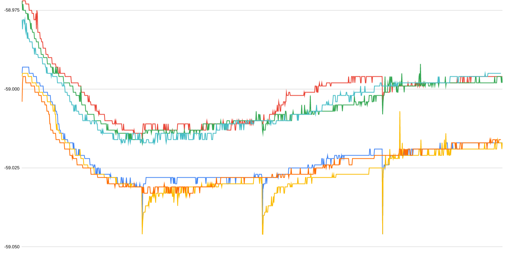
![]()
Microns. That shows <10 μm variation for 720 Z probes over three hours. Each ~1 hour block of 240 touches starts with a long up/down excursion. Indicated steps alternate between 1 and 2 μm because the actual microstep size is ~1.5 μm. The three downward spikes are the first touches after the long excursions and could be avoided by adding a small up/down hop after long up/down moves.
Other than those avoidable spikes, and a ~5 μm drift over ~20min (~80 probes) in the second hour, that looks like micron scale repeatability over usefully long time spans and cycle counts. Relative to a target of maybe 25 μm variation (match X&Y full step), that looks very encouraging and worth pursuing.
But
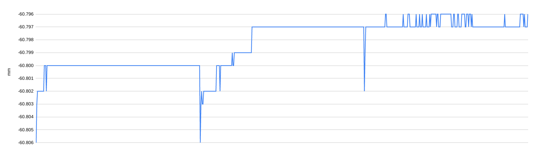
That 3hr stretch of wunnerful repeatability is cherry picked from data like this:

first big graph 
second big graph ...preceded by a bunch of manual data collection, preceded by a bunch of random thrashing trying to figure out what's the deal.
- The two graphs show about 30k points ((9k + 6k) x 2).
- Both are discontinuous;
- the first more so than the second.
- Only the one large-ish gap in the first graph represents elapsed time between sampling runs.
- Red/lower points: touch down/make contact
- Blue/upper points: lift off/break contact
- I can guess at causes for some but not all of the variation of difference between the two
Generally, I've been seeing that short term repeatability can be, and often is, very good -- and long term repeatability can be, and sometimes is, acceptable (relative to a target of 25 μm which is somewhat arbitrary but comparable with the full step stride of the X&Y axes and aimed at cutting just through ~35µm nominal thickness of 1oz copper cladding that isn't flat).
Some of the runs in the first graph show strong similarity in fine structure:
![]()
I've pretty well convinced myself that the wiggles in the initial downward slope reflect non-uniform microsteps. The distance/step cycle runs through two full steps. At least two of the 28-BYJ48 motors I've look at -- closely enough to notice -- show significant asymmetry between even & odd full steps. Haven't dug into that much yet, but for now I'm counting two full steps as the practical resolution of these motors. In the latest rev. I've shrunk the pulleys again to make two full steps move about 25µm for parity with the X & Y axes. (Finer string -> more turns fit -> less motivation for big pully diameter; more about string below.) These data were measured with 8x µstepping which is where the 1.5µm steps come from. While that's impractical "resolution", I'm much surprised that this marginally constructed device actually distinguishes single µsteps at ~16k steps/rev. While kinda neat, that's not really useful and as of right now I've dialed that back to half-stepping (~6µm/step).
Thermal expansion(s)
Apart from the finer wiggles, I think the general trend looks like different parts heating up differently. I'm guessing that the fast initial slope reflects the pulley heating quickly. Then the slower up-slope reflects the XY table growing taller as it heats up less quickly. That's a little less speculative because I can test that by unplugging the X&Y motors. The second-to-last spike-drop-slow-rise in the first big graph dropped like others then turned back up less quickly with the XY motors unplugged, which seems to corroborate that idea. The fact that there's still some slower exponential-like change happening suggests something else warming up. I'm guessing that it's the bulk of the Z axis heating up. Maybe changing the relationship between the stepper axle(s) and the tool clamp. ?.
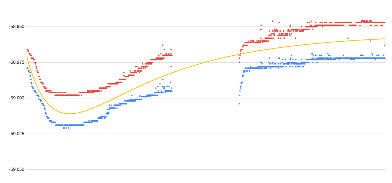
Anyhow, this kinda sorta validates the idea that the Z probe data reflect smaller and larger parts heating up quickly or slowly:
![]()
The yellow line is the sum of two exponential curves -- one faster and one slower. The gap reflects the time span of uncollected data.
The horizontal lines on that last graph above mark 25µm intervals, which is the variation I'm kindasorta aiming for. From my "artist's interpretation" curve fit, it looks like the longer time constant is about 45 minutes. That suggests that letting the machine sit for some small multiple of 45 minutes with the steppers powered would get well within 25µm of dimensions at eventual thermal equilibrium.
Not indicated there is the further effect of the "spindle" (dremeloid) heating up too.
The first big graph includes several temp cycles; the second big graph reflects longer kinda-continuous heating.
I think some of the trending in the first big graph correlated with room temperature.
So maybe something like...
I've been trying this idea: let the machine sit with the spindle running, room closed (doors/windows), and the XY table scanning back and forth across a diagonal similar to the extent of planned work at the planned XY feed rate, for a sufficiently large small multiple of whatever the long time constant turns out to be. Then probe/map the surface (because Z precision motivated by milling copper-clad board) and start a job.
Scripting gcode to loop scanning X&Y was reason to get after a >25-year-old to-do item: learn some expect (beyond most trivial use).
There there's yet more other stuff...
Z hoist cord materialFor a first try, I used the same white, three strand, probably-nylon cord that I've been using for the tool clamp. That gave the first encouraging result of close-enough-to-uniform 50 µm Z steps milling a small part.
![]()
While that finish cut sequence of starting at the top and stepping down demonstrated adequately holding a constant Z between equal increments down, it didn't really challenge repeatability of moving away (up) and returning to the same point. While that stuff showed pretty good short term repeatability for small motions, I was getting pretty random results from longer moves (higher Z lift). Like, more than 100 µm variability but I don't think I kept any numbers. Then I tried heavy carpet thread to see if that would be more consistent. It was, but not really convincingly so. But then there was other stuff going on that I didn't understand (see above) too, so: inconclusive.
For a different project idea a while back I looked for the lightest/thinnest Spectra® (UHMWPE) cord and found some 0.5 mm < d < 2 mm options sold for kites and spear/bow fishing. That didn't go anywhere and I didn't buy anything then. Looking again this time I discovered "braided" fishing line. Fishing people ("anglers" but does anyone other than anglers know what "angler" means?) use braided Spectra®/Dyneema®/generic UHMWPE cord with diameters down to less than 0.1mm. Prices at the nearest sporting goods monger were essentially flat up to 50lbs tensile strength before ramping up significantly for stronger/bigger line. So I picked up a reel of 50lbs-rated braided Spectra cord with nominal diameter of 0.36mm. Woot. Because neat.
That eventually looked like it would work well enough (first big graph). While the per-unit cost of enough of that is nearly nothing, the retail cost of >100x the needed length becomes the most expensive item in the BoM. So I went back to trying the carpet thread again. It kinda looked like that would work (second big graph). But...
Skipping steps - the wrong way
After much (muchly much) futzing, I've lately convinced myself that the Z stepper shaft(s) rotation is in fact actually drifting out of sync from where Grbl thinks it is. For now I'm believing that Grbl is doing the right thing with step pulses and not accumulating asymmetric rounding or some such subtle evil.
The weight of the Z axis hangs directly from the output shaft(s) of the lamest of geared steppers. Missing steps would be no surprise ... if the axis was drifting down as a result of missing upward steps. How does it miss downward steps and drift up?
:-/
I have half an idea what might be happening, and a couple of ideas to try...
...and so it continues. Bah.
-
Byproduct of debugging Z repeatability
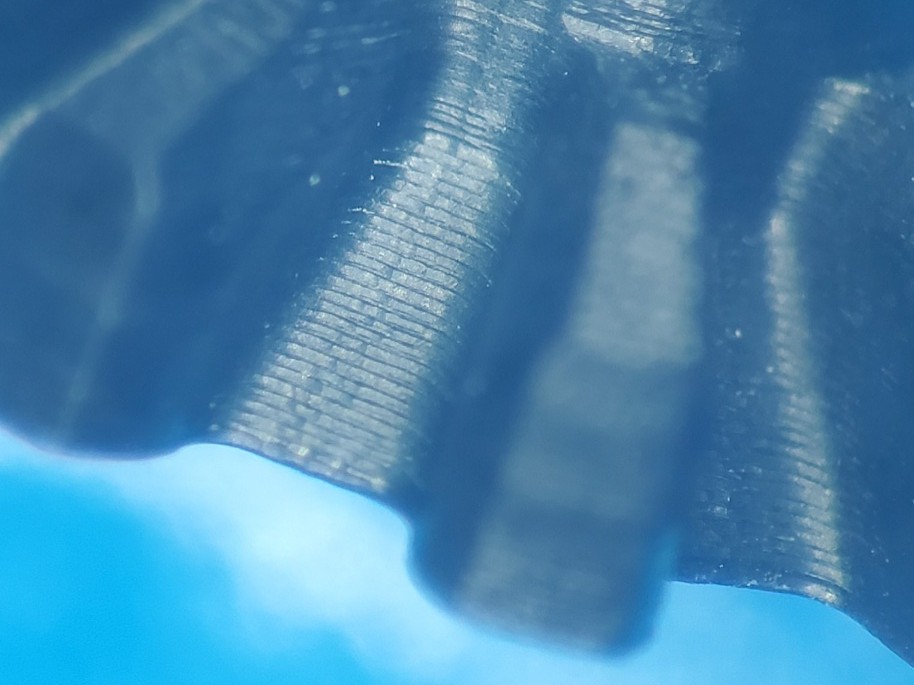
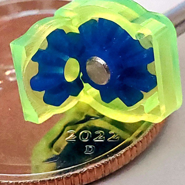
09/26/2022 at 21:28 • 0 commentsMore ornamental than functional, but skimming ~50µm from copper-clad board still tests control of cutting depth.
![]()
Copper figures "over" (but not really over) blue acrylic paint. Made by first cutting the blue parts, painting, cutting the background, then sanding the paint off the remaining copper. Sanding carefully -- the first try ended with entirely removing the copper from one spot while trying to clear a minor blemish from another spot.
-
Z v3 -- counterweight delete -- progress
08/17/2022 at 22:06 • 0 commentsFrom last week's episode...
The result is surplus torque and steps/mm, so the next rev can use a larger diameter to get more (all?) of the string wound onto the drum in a single helix of more nearly uniform diameter. Currently the steps/mm changes when the string fills the (thin) drum and winds back over itself [...]
So... yes.

In this iteration:
- larger diameter lift winch drum per last log -- this combination of drum diameter, material thickness and lift cord gets the full range of motion in a single layer of wraps (about two) for more uniform steps/distance
- space for a redundant hoist -- one motor still works but the chain of lightly constructed single points of failure holding the heavy/spinny/cutty part up from freefall might be too much minimality even for this project
- various other fixes/tweaks
(...and that little screw on the right frame side -- for stowing the counterbalance rig -- can go away now)
While assembling this rev I made a short list of minor tweaks for one more iteration that should be ready to share (because optimism).
-
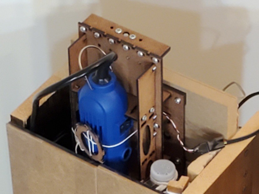
Z v3: counterweight delete (& other wins)
07/08/2022 at 00:07 • 3 commentstl;dr: it works -- scroll for gear example
The proto-concept for this project had a weak Z axis moving the heavy tool horizontally. For reasons, the idea got switched to conventional vertical Z with a counterweight helping the weakly driven axis. And so it was, from then until a post-MRRF epiphany about how my whole concept of Minamil's Z axis has been broken since that early reorientation.
So...
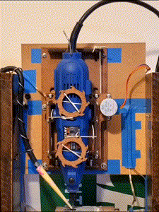
Here's a cheaper, smaller (vs v2.x), stronger Z axis that doesn't need any counterweight:
![]()
Because gravity is free anti-backlash (for a << g), and there's room up there to bodge on a bigger motor.
The last log entry showed a lashed-up proof of concept but not yet any attempt to see if it would actually work in anger.
Since then: to CAD and laser cutter... Largely because I'd already planned to try a different arrangement of the slidy parts.
Behold: Z v3
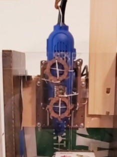
Trading a ~$10 stepper+leadscrew unit for a ~$2 geared stepper, the ubiquitous cheapous 28BYJ-48:

longer throw, too :) The motor turns a laminated (big disk/little disk/big disk) winch drum to haul the carriage up a bit of string that seems to be sufficiently unstretchy.
![]()
The result is surplus torque and steps/mm, so the next rev can use a larger diameter to get more (all?) of the string wound onto the drum in a single helix of more nearly uniform diameter. Currently the steps/mm changes when the string fills the (thin) drum and winds back over itself -- but that won't really matter until someone tries cutting much thicker stuff than I have so far.
Result: yes
For a first "real" test, I tried cutting one of the little bevel gears from the recently shrunk demonstration project:

little bevel gear -- 7.6 mm diameter Those look like encouragingly uniform 50 μm step-downs. That's really the main point of this log entry. ☺
Besides losing all the counterweight rigging, this version gains some other wins:
- reduced cost
- top of the machine is solid when not holding the rotary tool (vs. moving/fragile parts)
- longer range of motion (>70mm -- obstructed to ~66mm by limit switch in this rev)
- smaller/shorter than V2.x slides
- stiffer than V1.x slides, and I think not much less stiff than V2.x
- operates without tool mounted and counterweight rigged (or a finger under the empty carriage)
- option of using two longer rods vs 3x 100mm rods, or one long+one short; four bearings on two long rods should better resist twisting of the tool carriage
- long rods, if used, supported in middle to maintain stiffness -- otherwise prolly too long for 6mm
For reference/comparison/contrast:
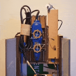
V1.x
![]()
(lame photo)
Uses same slide mechanics as X & Y. Most compact.
V2.x
![]()
(also lame photo)
Mechanically based on two copies of the X/Y slide in tandem. Because that seemed like a thing to try. Much larger than v1.x. Used relaxed size constraint (XY axes limit minimum footprint area) to spread out the bearings for greater stiffness - probably well into diminishing returns. Lower two bearings spread 1/3 wider. Upper bearing much higher above lower bearings relative to v1.x, especially in upper range of motion. Room for two motors+screw units, but didn't try/need that in Z with counterbalance and mild acceleration. Added a lot of height overall. The long tail of the moving tool carriage stuck up vulnerably from the top, while the "telescoping" configuration didn't add any benefit for this axis -- reasons why the next rev was going to drop the telescopiness for a less unconventional arrangement of bearings in a shorter tool carriage running on axially offset rods in a similar tandem base.
-
#MRRFX and whY rethink Z
06/27/2022 at 23:48 • 5 commentsMRRF
Last weekend I parked the current iteration of this project on a table at #MRRFX for a day. MRRFX being the tenth (Xth) gathering of the Midwest RepRap Festival (MRRF) "the largest gathering of 3D printer enthusiasts in the world!". There I met some really neat people, learned some stuff I didn't know I didn't know (busy day for Dunning & Kruger), and realized that I'm doing Z wronger than I thought.
I have only casual acquaintance with 3D printing and nothing of the sort to show, but teh Internetz said a few mill/router projects had crashed the show in the past without scandal. This year Joe Spanier brought his aluminum-eating Milk Cr8, and Duet3D had a colorful router running their controller(s) -- all news to me.
The trip was kind of an impulse idea decided only a few days before and prepped in haste. I wasn't at all prepared to be socially competent or retain names and contact info for many of the people who stopped for substantial conversations -- about this and about their own projects and experience too.
soft threads
Prompted by meeting Stefan Hermann of CNC Kitchen, I checked out some of his work including his 2019 review of threaded inserts for 3d prints where he measured torque-out and pull-out strength of several different types of heat-set brass insert -- including none. For "none", he drove screws into bare holes in relatively soft printed material. He confirmed expected low resistance to torque-out -- a reason why inserts exist. But, contrary to expectation, he measured pull-out strength nearly equal to the better inserts and several times better than the simplest/cheapest insert.
Most of the minimized design of this little CNC project is held together with short machine screws run edgewise into soft "hard"board -- which seems like it shouldn't work at all. The very low resistance to torque-out i.e. very great vulnerability to stripping threads out of hardboard viscerally reinforces the expectation of weakness. Stefan's finding that un-reinforced threads in relatively soft material can usefully resist pull-out even when vulnerable to easy torque-out gives somewhat better rationale than simply shrugging at the unexpected result that the method of assembling these "Minamil" designs apparently works.
A consequence of low resistance to torque-out -- i.e. ease of stripping threads -- is that while screws can be used to hold parts together, they can't be used to used to draw parts together and generate clamping force in the usual way. Most of the screws in one of these linear slides hold the clamps that hold the rods & bearings. A very early lesson in working with this design was to not use the screws to close the clamps but instead to mash the clamps directly then carefully turn the screws down to hold them. Also it becomes Very Important to take care to re-engage existing threads when removing/replacing screws in previously formed threads.
Z realization
Counterweight?![]()
We don't need no stinking counterweight!
but first, some history...
(or skip to last heading)
I first used one of the prototypes of the slide used for X & Y because it was handy to try. Then I used the same slide as X & Y and added a tool clamp to it because it was already done in CAD. That's the currently published design, it works, and later developments have not compellingly surpassed it, so that's ok. But it's not really a satisfactory endpoint because there's no reason for the Z axis to mimic the X+Y axes when it does a different job under different constraints. (for completeness: the zeroth Z axis was a fixed stand over the XY table)
Gravity, obviously. The counterweight arrangement got me over that hurdle and I mostly stopped thinking about it. Until recently when... I'll come back to that down the page.
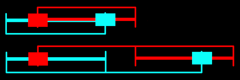
Cutting forces at the tool tip act on the Z slide through a pretty long lever, which ups the ante for stiffness. The size and clearance requirements of the XY stage set a minimum footprint. There's little reason for the projected area of the Z stage to be any smaller than that. The length of a rotary tool + Z travel sets a minimum working height above the XY stage. Keeping the Z slide shorter than that does have some benefit in allowing a shorter closed storage height with the tool removed, but I don't give much weight to that advantage over allowing growth in height in trade for other benefits. I built the current (2nd) frame with (initially) unallocated space under the XY platform and extra height to protect the maximum upward extension of the currently published Z slide, then didn't feel bad about growing even taller when we get to that... So there's plenty of room for the Z slide to spread out its bearings, both horizontally and vertically, for greater stiffness. The less-minimal Z axis in recent photos and shown at MRRF grew both horizontally, to spread out the two lower bearings, and vertically, to give the upper bearing greater separation from the lower pair -- especially in the upper range of travel. It also spreads out the clamp saddles and some details of the clamp/slide interface significantly stiffen the moving assembly -- at least in my imaginary FEA -- but I don't think that was the weak spot so I don't expect much gain from that.
The last couple of iterations gained length by copypasting the slide into a tandem pair and deleting half of the (doubled) hardware:
![]()
But this is unnecessarily unconventional when the only gains are lazy CAD and extending the bearing span well into diminishing returns, especially in the lower range of motion. Also the top end of the moving part is vulnerable unless protected by an even taller frame. So this could use instead a more conventional arrangement of fixed rods and moving bearings (or: all the bearings either fixed or moving).
...and some historically projected future...
If keeping with the same length rods (for simple BoM), the next iteration might look more like:
![]()
I think that's enough longitudinal bearing span to be not the weak link. When the rotary tool is not attached the top end will be lower, fixed and relatively less fragile. An obstacle has been working out how to get all of: protected leadscrew, access for backlash adjustment, best clearance of the fixed part above the work surface, and simplicity. Because motor placement constraints not illustrated. But I think that's about to cease to be a problem.
Oh yeah, I said I'd get back to gravity down here. The Z axis needs help to cancel gravity. A constant force spring (think retracting tape measure) would have been great but I couldn't find a suitable part and anything anywhere near the ballpark was radically incompatible with objectives of low cost and avoidance of special parts. I noodled a few ideas for a counterweight within the dimensions of the frame, but complexity and parts. While somewhat awkward, the beverage bottle beam balance works and can be made from garbage. Solved.
A recent exchange on the HaD discord got me thinking again about the "solved" problem that I'd stopped thinking about a while ago. Lightbulb: retracting reel badge/ID/key holders. The market seems to have settled on a de facto standard of about 30mm d. x 10mm thick reels pulling about 100gf for larger or smaller fractions of $1 in smaller or larger quantities. Balancing a tool + slide mass <1kg would require a bank of <10 of those in 30mm x <100mm across for <$10, which could sit behind rather than above the slide given a means of turning the string tension through ~90 degrees. That might possibly work out as another improvement of the/a next iteration of the Z axis. But I think that too is about to cease to be a problem.
...but -- D'oh!
I've been barking up trees in the wrong forest.
Talking with lots of real live people at MRRF, answering real questions about stuff that I'd long since stopped muttering to myself about apparently helped break up some prematurely congealed beliefs about what and why. I suppose that's the ideal of "peer review". Just before going to bed last night, while sketching options for where to put the motor+screw unit in the last (i.e. next) Z slide diagram above, I had a monolith moment.
Those nifty little motor+screw units, while contributing to apparently-commendable results from a compact assembly of low cost parts in the XY table, also cause unnecessary problems in the Z axis which has no need of their benefits. While they work well in XY; I wouldn't have even begun to think any such thought for Z at all if I hadn't tricked myself into the mirror maze by ... how really?
I suppose it went something like this:
- #CDCNC driven by three of the same little motors with steeper pitch screws, with light Y vertical and heavy Z horizontal
- making the first iteration of the current XY table under the assumption that it and a single Z slide would end up in the same configuration -- likely by subbing first XY then Z into the same frame
- discovering that the shallow-pitch leadscrews weren't going to move anything vertically without some extra stuff to cheat gravity
- deciding that if I had to add more stuff to an axis, it may as well be the Z axis which moves ~invariant mass less frequently and more slowly (lower acceleration) over shorter distances.
- . . . in which decision I hid from myself the assumption that the Z axis "had to" use the same motor+screw drive as the horizontal axes
So, trying again: with the tool-bearing Z axis turned to vertical, it:
- will have to lift 500g < m < 1000g
- which should require lifting force greater than any upward reaction forces from the tool tip
- will descend with acceleration << 1g
So the axial load on the axis should never switch direction.
This sounds like a job for the king of cheap geared stepper motors: 28BYJ-48 (unipoleotomized). Sufficient torque (I think) and awful backlash won't matter.
Maybe, pending actually trying it. There may be too much stiction in the gears for that motor to move by consistent small increments. And I'm not sure how to get a sufficiently inelastic coupling between motor and slide. But I think I need to just try with what I've got and see how well or poorly it works.
- Shallow-pitch leadscrew: gravity is enemy
- Cheap geared stepper: gravity is anti-backlash
Or so goes the (new) theory.
update: GIF above shows first whack at 28BYJ-48 doing Z. Haven't tried actually cutting anything yet. Next rev of Z slide in mind will be shorter and mount motor below top of the slide i.e. much less stuff sticking out of the top of the box.
-
Runout reduction revisited
05/18/2022 at 02:15 • 0 commentsPoorly controlled runout has haunted this project since first musings about its silly predecessor. Pulling back from an earlier somewhat helpful idea seems to have helped to escape a local maximum. At least for parts that can be finished with a single tool.
To prove the pudding, an even smaller differential gear set ̶i̶n̶ ̶p̶r̶o̶g̶r̶e̶s̶s̶.̶.̶.̶ done:
![]()
I prolly should add something here about reducing runout with cheap dremeloid clones...
Already kinda glossed the method in this log. The main thing since then is just getting better at getting more predictable results with less effort. Also I partially undid an earlier attempt to constrain the poorly constrained collet, which made it easier to just push it around until it points in the right direction.
The "in progress" pic:
![]()
Done with a cheap generic DremelⓇ-like rotary tool.
Minamil 2dc: a minimal CNC mill
Each axis: ̶$̶5̶ ̶$̶8̶ $10 motor+lead screw, 3x LM6UU, 3x 6mm x 100mm rod, 1/8in hardboard, PC case screws


