Close
0%
0%

DIY Echosounder

Creating a real echosounder from scratch

Similar projects worth following
When building my autonomous boat ( https://hackaday.io/project/166552-small-autonomous-survey-vessel ) I soon found that I would like to have some kind of echosounder on it to map the depth and prevent it from running aground. Unfortunately echosounders are still rather expensive. Only recently with the introduction of the Ping sonar by Blue Robotics it seems to get into the realm of hobbyists like me. At US$280,- it is still a considerable investment. And for years I've been looking for DIY sonars since I just wanted to make one myself. But these are rare, not to say virtually non-existent. Since I've been working with Sonar based instruments for years I also know where the problems are. Let's see if we can get it done this time.

There are a few problems when it comes to building your own sonar from scratch.

  • Get hold of the active element required for sonar: the transducer. Transducer material (usually piezo ceramics) is hard to get in small quantities. Usually they are made to order, and a few hundred dollar for a single batch is pretty common.
  • Mechanical design of the transducer. Very little information on this is freely available online. Most companies keep the design process to themselves. And there is some design software available, but that's all commercial as well.
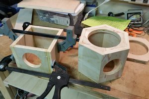
  • A watertight housing for transducer and electronics. Not  a trivial thing. My experience is that it is very hard to keep water out since it tends to creep through the smallest of holes. Extra complication here is that you will also need some way of connecting the electronics to the outside world.
  • The electronics. Although that is not very complicated, it does require some specific components like  transformer and tuning coils which are also not as easy to get at the average hobby-electronics store.

  • Electronics

    Cees Meijer09/21/2020 at 20:42 0 comments

    A Sonar system consists of several blocks:

    • A transmitter stage. Usually a push/pull switching driver consisting of a pair of power FETs and a driver
    • A frequency burst generator. An oscillator with gating to create a short burst at the required frequency
    • Amplifier and filter for receiving the return signals
    • Digitizer to sample the return and make it available in digital form.

    For the burst generation and sampling it seems obvious to use a micro-controller board. Preferably one with a decent clock speed so it can support a fast AD converter and a high frequency burst signal with decent precision. As the sound travels through water at 1500 m/s, you will need to sample at at least 150 kHz to get to a centimetre resolution. And I chose a 512kHz piezo, so the controller needs to create a square wave burst at this frequency.

    The standard Arduino boards are obviously too slow for this, so I thought of using an ESP32 board like the WEMOS Lolin32. But I soon found out that it is hard to get a good sample rate on the AD inputs. Even when using low level programming it seems that 90 kHz is about the maximum. So I soon came to the Teensy boards. A standard Teensy has an AD sample rate of up to 400kHz. Added benefit: the Teensy platform focusses on audio processing and sampling so a lot of functionality is available out of the box.

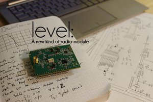
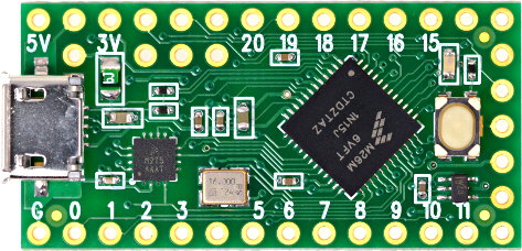
    It looks like even the cheapest Teensy, the TeensyLC (yes,LC for Low Cost)  might be sufficient for this task. But will it also be able to generate the transmit pulse and necessary control signals ? I will need a 512kHz burst, and some analogue ramp signal for the Time Variable Gain amplifier. And it turns out that this is not just possible, its also very simple.
    int TX_Pin=23;
    unsigned long TX_Freq = 512000;
    
    void setup() {
     analogWriteFrequency(TX_Pin, TX_Freq);
     analogWriteResolution(10);  // analogWrite value 0 to 1024
    Serial.begin(115200);
    }
    
    void loop() {
    // Transmit burst
    analogWrite(TX_Pin,512);
    delayMicroseconds(20) ;
    analogWrite(TX_Pin,0);
    delay(5);
    // TVG Ramp
    for (int val=0;val<1024;val++)
     {
     analogWrite(A12,val);    // Use the DAC output on A12
     delayMicroseconds(100);
     }
    }

    This simple Arduino code generates a 512 kHz burst, and an analogue ramp signal on the dedicated DAC output:

    The first image is a continuous square wave of 500kHz, just to show how accurate the PWM frequency setting is (very accurate). the second shows the burst signal, which is slight longer than the 20 uS delay, probably because it also takes time to execute the command that switches it off. And the last image shows the linear ramp that starts 5 mS after the transmit. The ramp is linear, but it could be any shape, either from a formula or from a table.

  • Housing and Transducer mounting

    Cees Meijer09/15/2020 at 11:17 0 comments

    For the echosounder I need to create a housing  that has the following specifications:

    • Waterproof to a few meters
    • Can be opened and closed
    • Contains feed-through for cables or connectors
    • Cheap, preferable made from off the shelf parts

    Now I designed and built several subsea housings in the past as it is part of my job, but these are always custom made at a professional machine shop. Usually they consist of Delrin plastic tube with special shaped end-caps that have double o-rings seals.

    There are a few examples around of people who built waterproof housings, and most of them use standard PVC parts as available in any hardware store. The one I like a lot is this one:

    https://thecavepearlproject.org/category/diy-underwater-housings/

    Not only do they use standard parts, the result looks really good.

    First I thought this concept was not usable for me since these PVC parts are produced and sold only in the US, but recently I found that they are sold on Amazon and actually by Formufit online as well and shipped worldwide (as far as I can see)

    But this also may be over-complicated for my design. So I just started by drawing the piezo-disc, and the the nearest size PVC tube I could find (50 mm) to see what i could do with my 3D printer.

    The grey part is standard PVC, the yellow is what I intend to print. The channels as visible in the cross-section view will be used to pour the epoxy or PUR resin in, which will seal the transducer element. The idea is that the 3D printed part will form the backing on the transducer. And when I print this using a  30 - 50% infill with honeycomb structure it will be both very stiff, and filled with air which will block acoustic reflections from the rear.

    Remains the top section, which I'll have to close in a way that it can be opened.

    And yes, the transducer end works out as intended. After soldering a thin coaxial wire to the piezo disc I can glue it on the base.

  • The Piezo discs

    Cees Meijer09/09/2020 at 18:29 2 comments

    If you search for 'Piezo Ceramics' you will soon find that there are several (not a huge number) suppliers. Most of these suppliers however require that you send them the specifications of the required parts so they can make you an offer for something that is basically custom made.

    Only recently some suppliers offer some specific parts from stock

    The German company PI (Physik Instrumente) has a store with some selected discs at reasonable prices. They also have really nice section with technical info on Piezo materials

    STEMiNC (Steiner and Martin Inc) Sell parts in small quantities, but the shipping and handling are relatively expensive if you only need one or two pieces.

    And of course there is China. There are plenty of manufacturers there, and thank to AliExpress these are also approachable to us (those who do not speak or read Chinese ...)  Here the choice is almost overwhelming, but it's not always clear what is available in small quantities or what the specs are for a specific item. In the end I opted for SOARPiezo. :

    Ultrasonic Piezoelectric Ceramic Disc PZT 40x4mm-PZT5

    A 
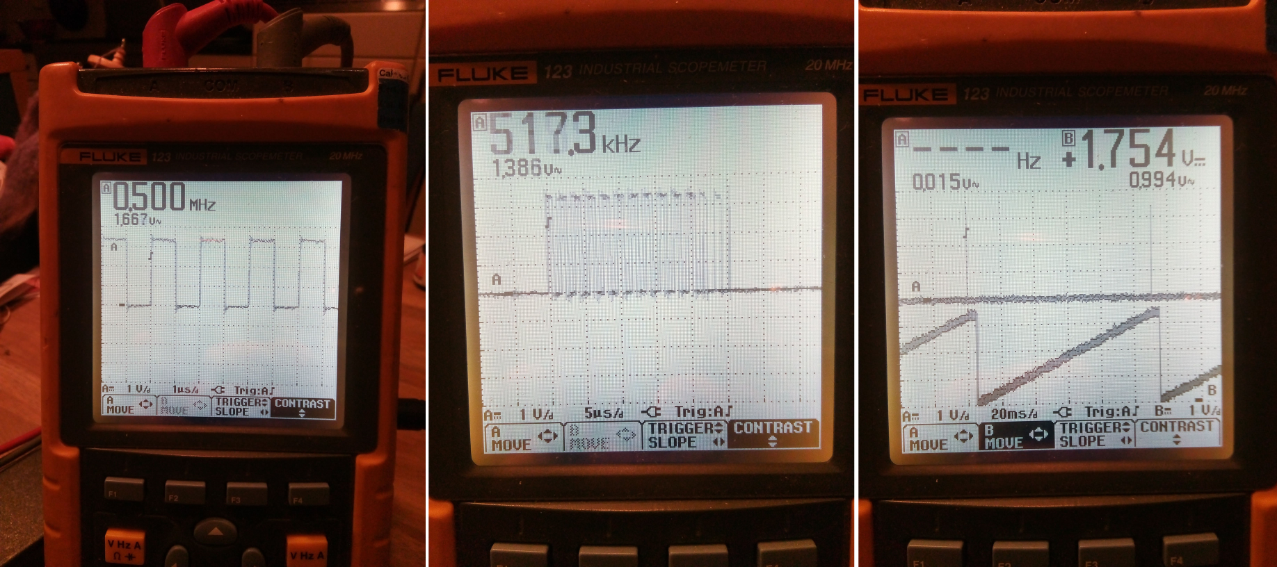
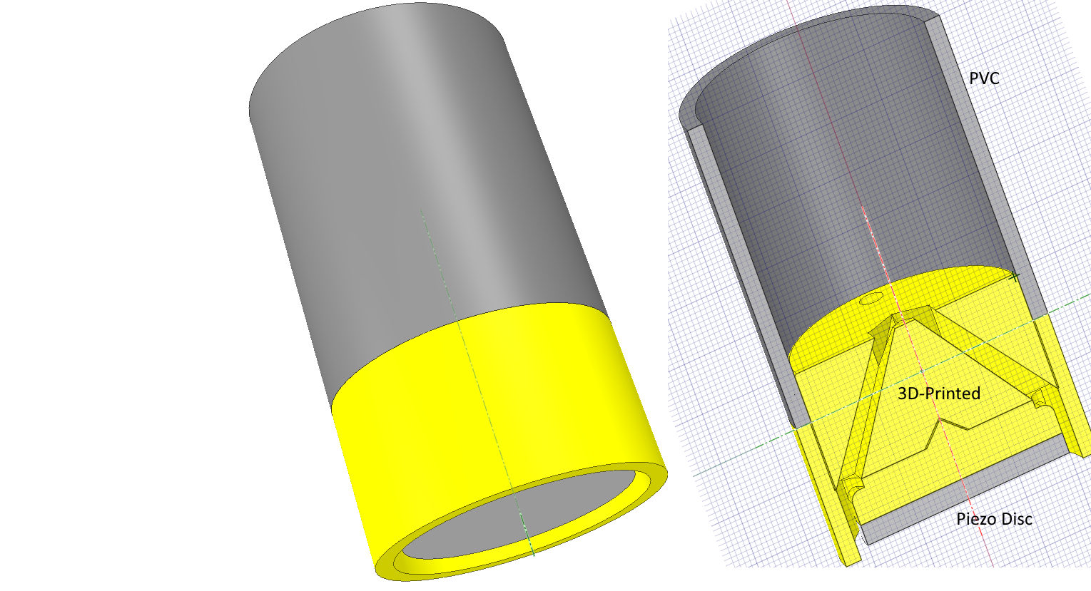
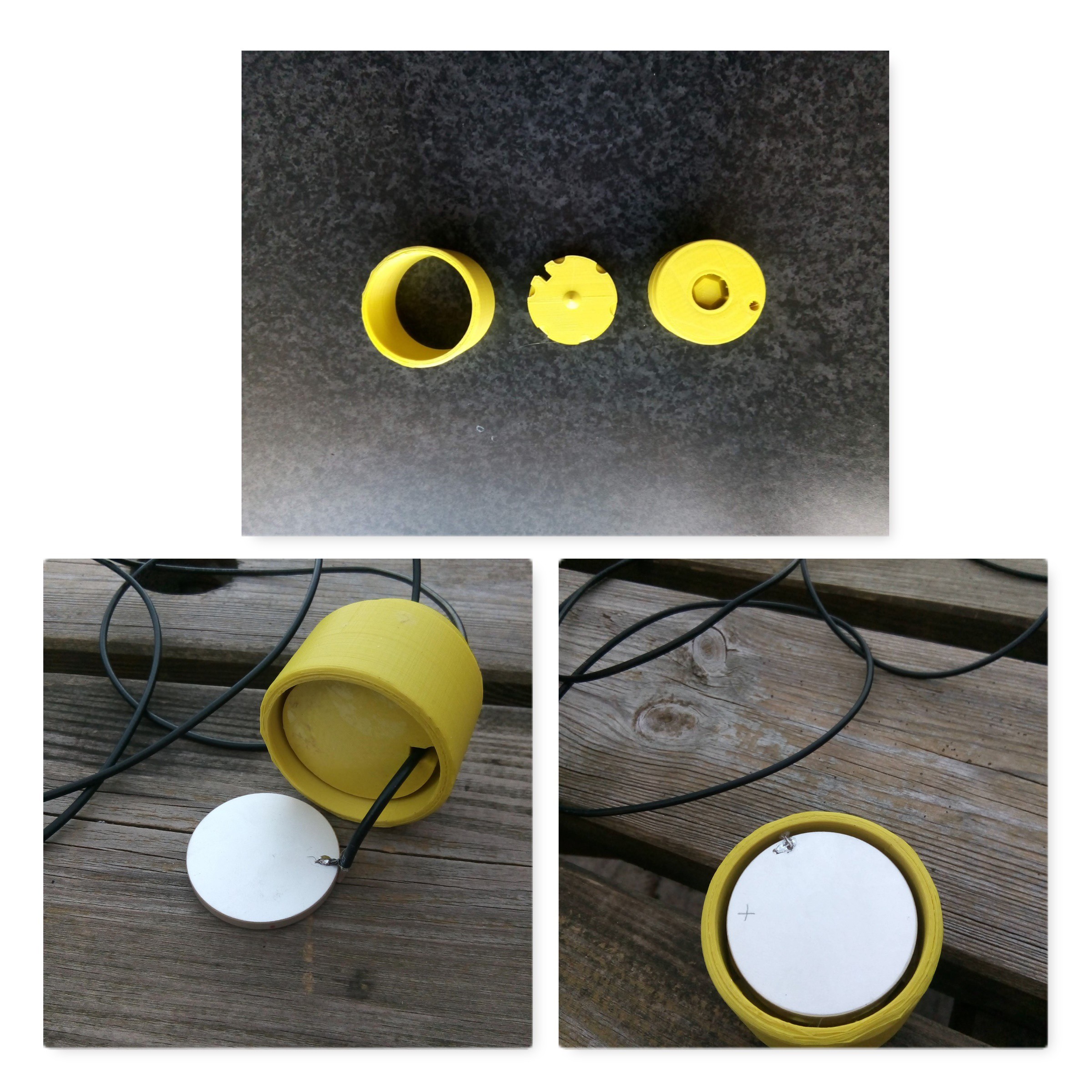
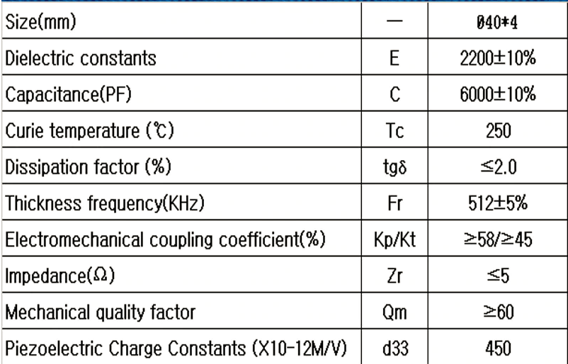
This disc has a 'thickness frequency" of 512 kHz which is a frequency that is commonly used for short / medium range echosounders. Depending on circumstances, ranges of 50 to 100 m should be possible.
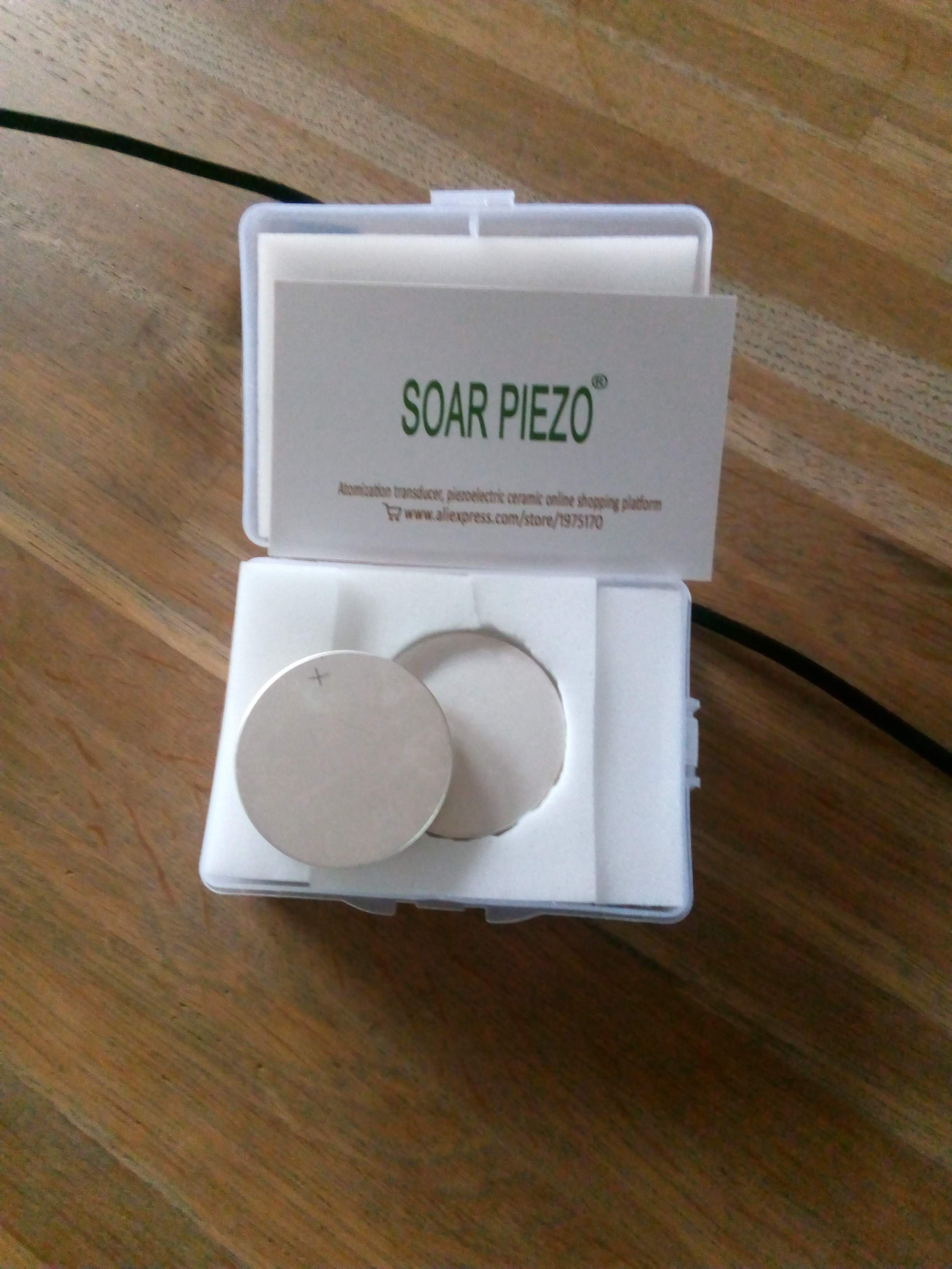
    These discs are €5,20 each, and with a €7,- shipping that is not too bad. So I bought 4, and they arrived in less than 2 weeks:


    Nice touch: they marked the '+' side. Not relevant if it is used  as a single transducer echosounder, but very nice to know if you want to build an array where the phase of the individual transducers must match.

View all 3 project logs

Enjoy this project?

Share

Discussions

light24bulbs wrote 09/11/2022 at 20:40 point

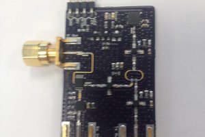
Fascinating stuff. I wonder if you could find out who is supplying parts used inside commercial fish finders and simply order those. After all, they are the right specification already. It might also be possible to hack one. Makes me want to order a transducer and see what I can get out of it.

I've had some luck on Alibaba with finding the manufacturers of a complete object and getting them to sell me a subcomponent. After all, they have it. 

  Are you sure? yes | no

mdidomenico wrote 02/17/2022 at 14:24 point

any updates on this?  i'm very interested in doing something similar, but instead of a custom piezo disc, use a standard 200Khz airmar transducer.  i'm not an EE so i got stuck on the amplifier section

  Are you sure? yes | no

nejc.likar wrote 05/01/2021 at 14:03 point

Hi,

I wonder about thickness / radial mode vibration differences.

Is for a project like this (sonar) necessary to choose thickness mode vibration?

Many piezoelectric discs have their thickness mode vibration frequency very high (MHz), which might be too high for underwater sonar application.

The commercial sonars work with two frequencies (50kHz / 200kHz). So they use also radial mode vibration. How is this possible? 

Thank you and regards

Nejc

  Are you sure? yes | no

ruegalfonso wrote 02/23/2021 at 20:16 point

The scope images have been very inspiring for me.

Thank you!!

  Are you sure? yes | no

Cees Meijer wrote 02/23/2021 at 21:42 point

You're welcome. Glad this project (even though there is not much progress) is useful after all...

  Are you sure? yes | no

Jonathan wrote 12/14/2020 at 21:01 point

Hi, pardon the ignorance of this question, but in sonar circuitry, what is the benefit of a Time Variable Gain amplifier?  Would the program driving the operation of the receiver continually increase the gain of the amp the longer the return 'ping' took to arrive, assuming that the longer the duration, the deeper the water and the weaker the return signal?  Also can you recommend any good text on sonar fundamentals?  Thanks.

  Are you sure? yes | no

Cees Meijer wrote 02/23/2021 at 21:48 point

Yes, you are completely right about the use of TVG, that's how it works. Regarding a text on sonar fundamentals: besides Wikipedia, I would not know of a real good one. I usually Google 'sonar fundamentals' and sometimes I find something useful.

  Are you sure? yes | no

Tom Nardi wrote 09/15/2020 at 06:20 point

Looks very interesting for when (or more accurately, if) I ever finish my ROV. Right now it's just exploring the depths under my desk...

  Are you sure? yes | no

Cees Meijer wrote 09/18/2020 at 20:46 point

Sounds familiar. My 'Autonomous Boat' is still far from autonomous, and I have not used it to collect data yet...

  Are you sure? yes | no

Similar Projects

Does this project spark your interest?

Become a member to follow this project and never miss any updates