0%
0%
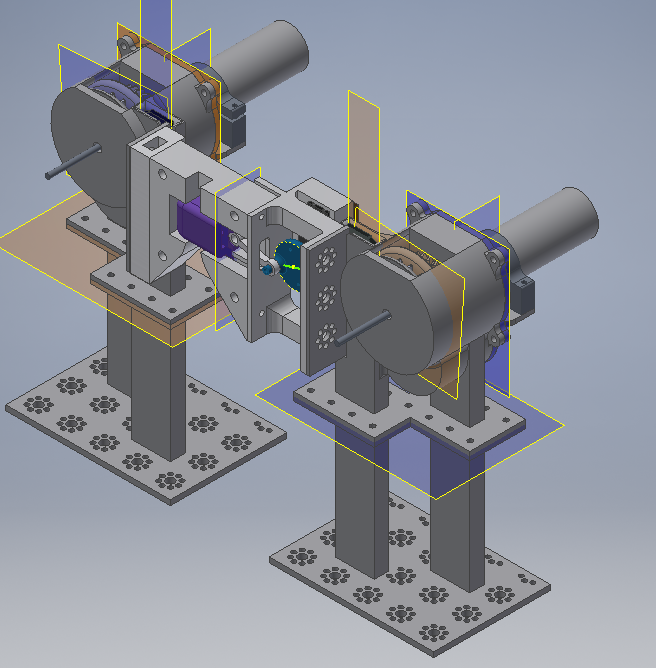
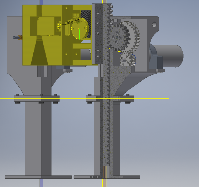
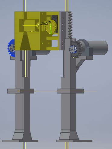
Lift and Lock Mechanism | FTC Robot (2018-2019)
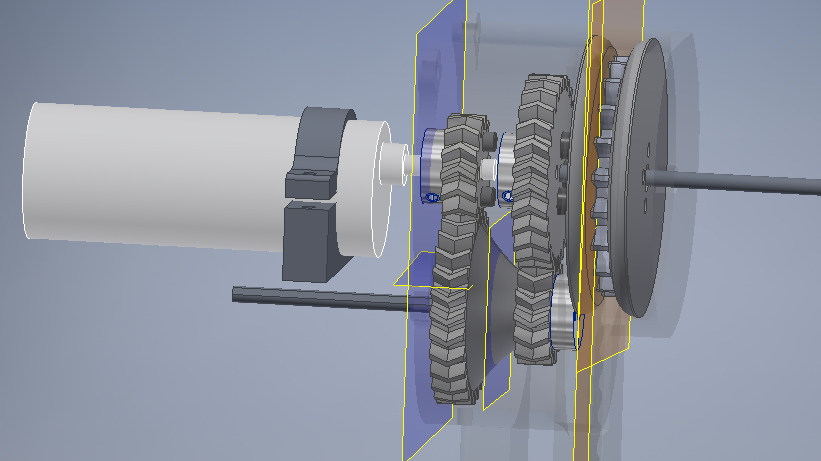
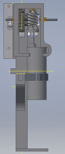
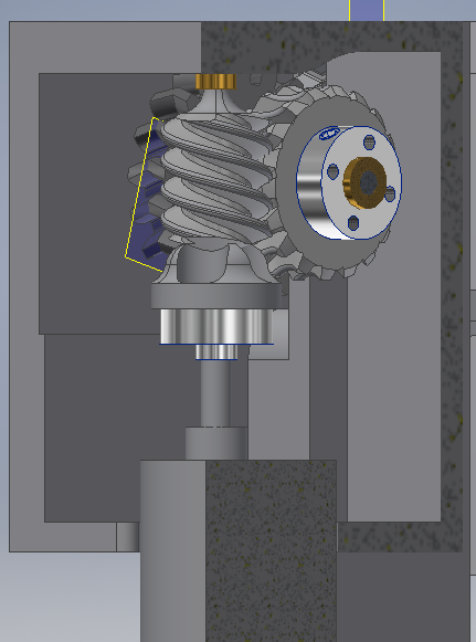
A servo-powered deadbolt attached to a rack-and-pinion based design, which locked to the lander and lifted the robot off of the ground.
 Silas Waxter
Become a Hackaday.io member
Already have an account? Log in.
Just one more thing
To make the experience fit your profile, pick a username and tell us what interests you.
Pick an awesome username
hackaday.io/
Your profile's URL: hackaday.io/username. Max 25 alphanumeric characters.
Pick a few interests
Projects that share your interests
People that share your interests


")
 Michael G
 Nathan Peterson
 Aaed Musa
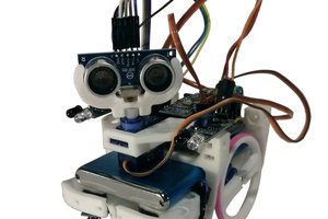
 Dasaki