0%
0%
Fixing up an old Pioneer 3-DX
Found some old robots in e-waste and will try to fix/modernise them
Become a Hackaday.io member
Already have an account? Log in.
Just one more thing
To make the experience fit your profile, pick a username and tell us what interests you.
Pick an awesome username
hackaday.io/
Your profile's URL: hackaday.io/username. Max 25 alphanumeric characters.
Pick a few interests
Projects that share your interests
People that share your interests
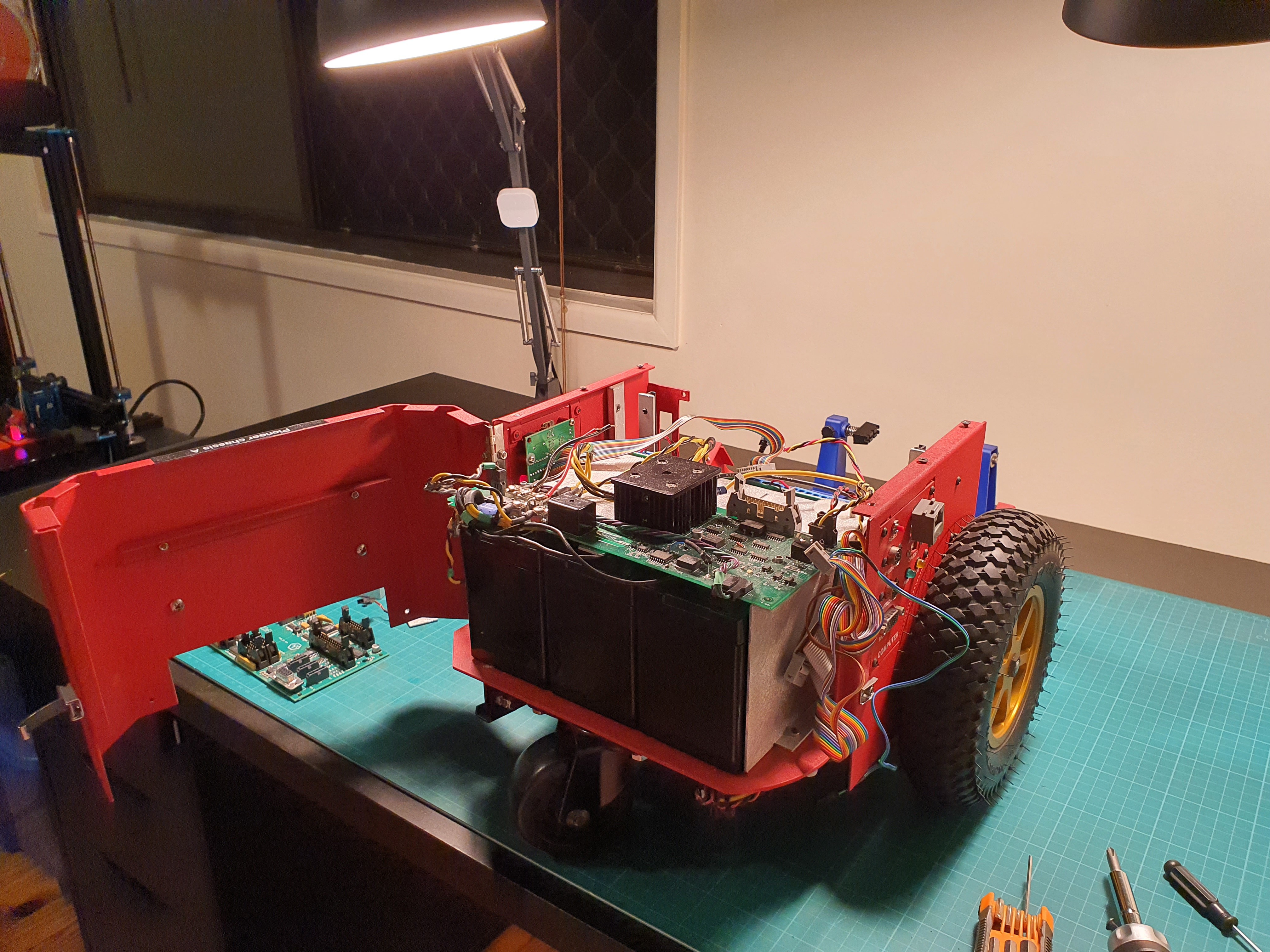
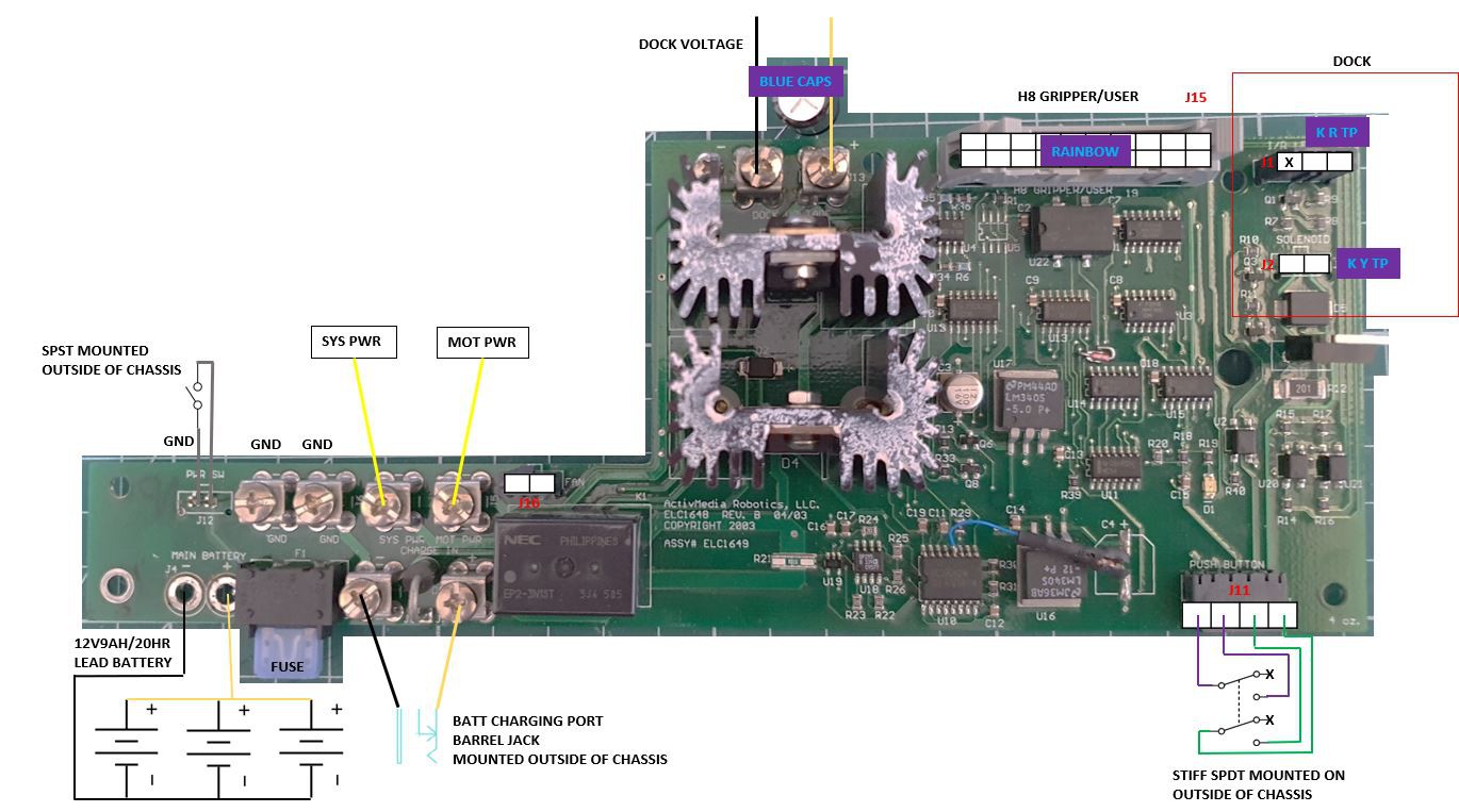 DOCK: Pioneer chassis has a self charging dock on the underside. Power board has a port J2 to control a solenoid which lowers an arm to make contact with pogo pins. I am assuming the robot aligns with the dock with IR, and that there are IR emitters supplied by the power board at J1 and receivers are connected elsewhere but it could be doing both from the power board. Dock charges through the dock voltage screw terminals J13-14.
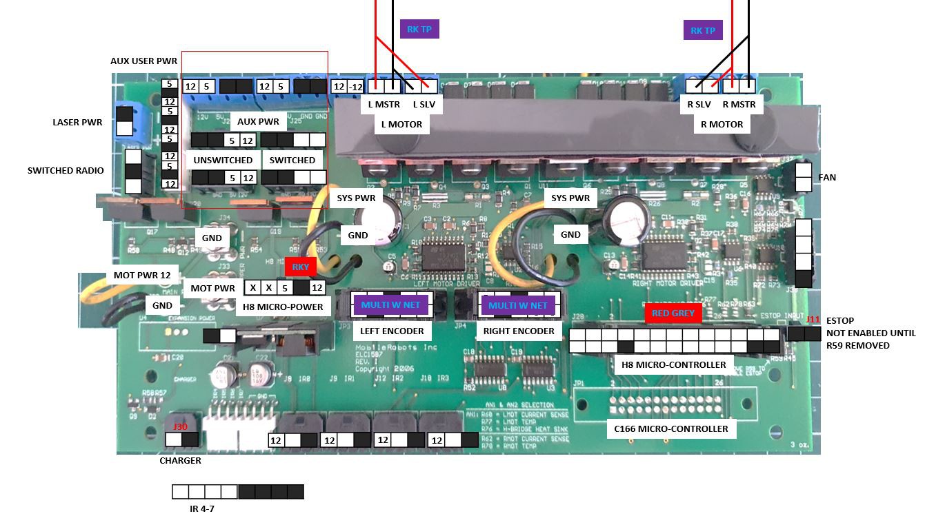
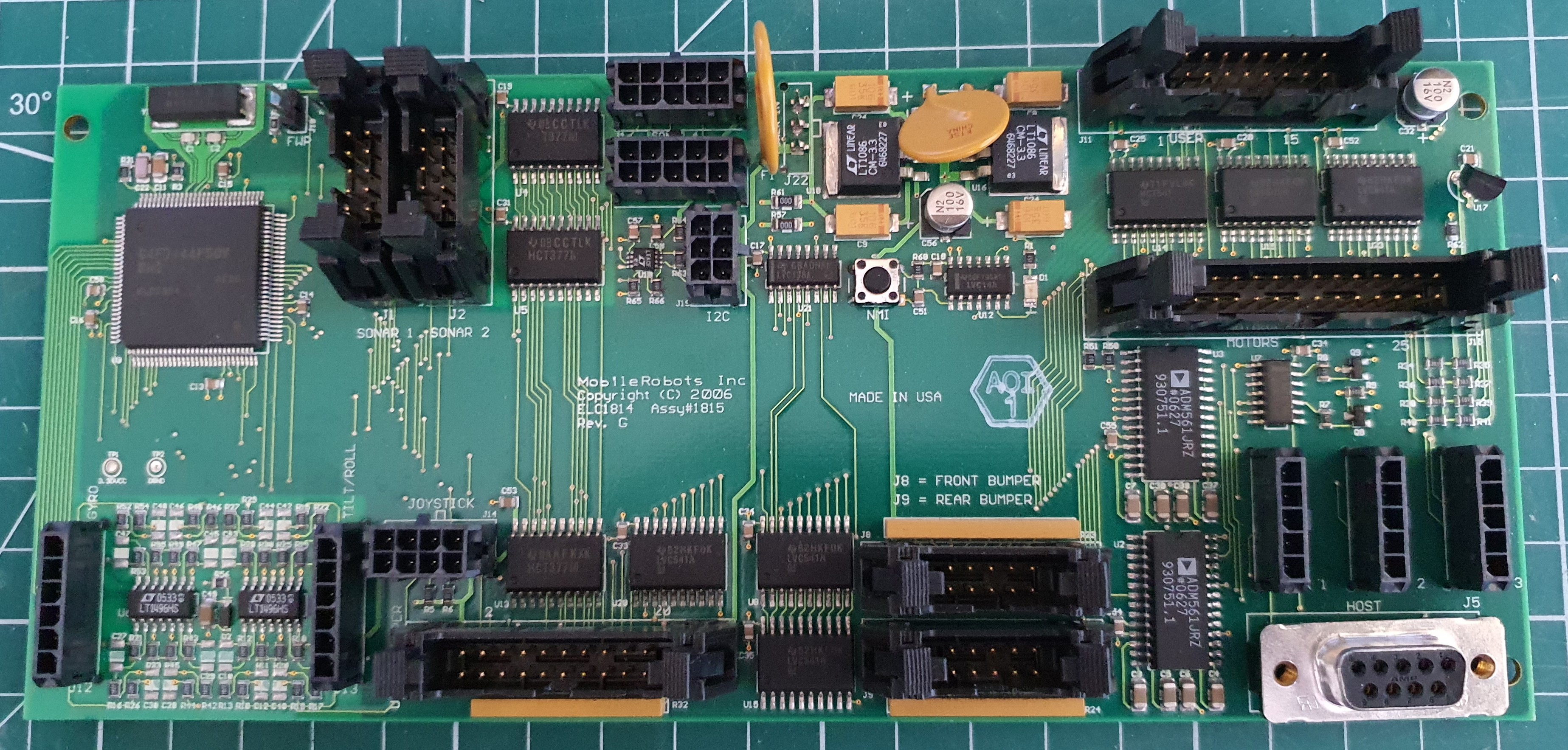
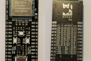
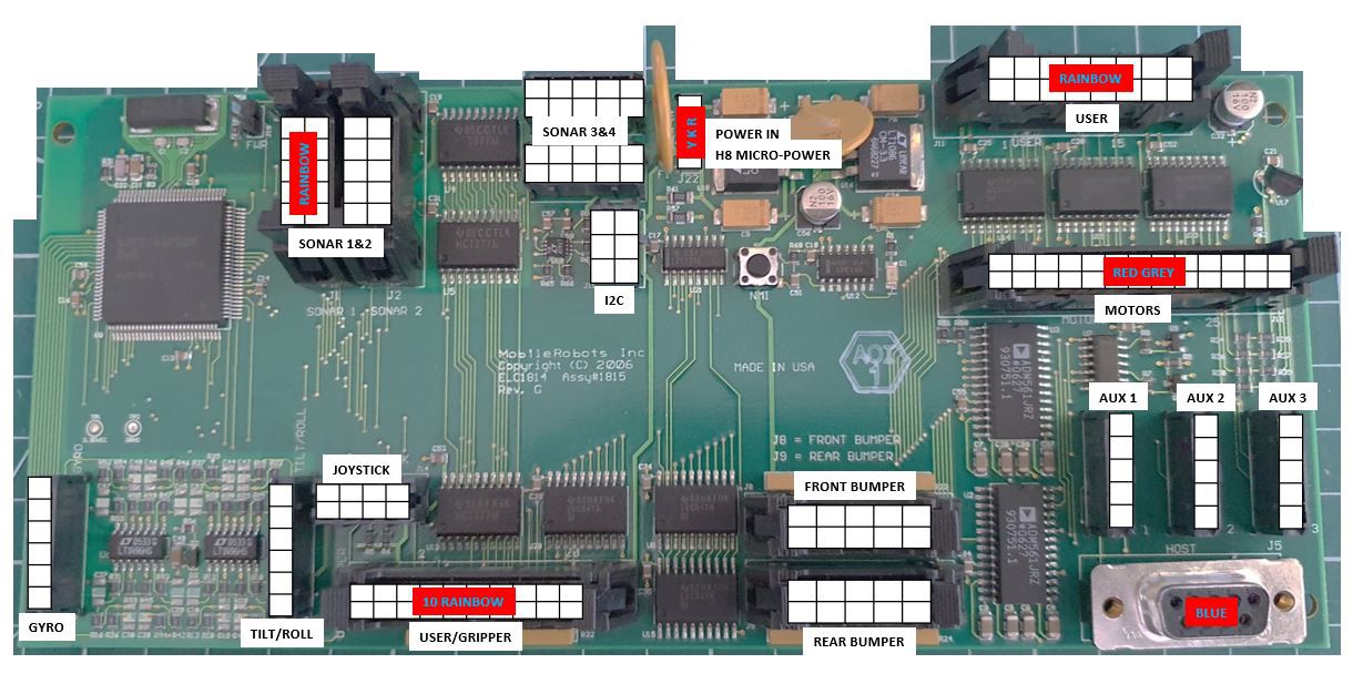 I intend to replace this with a more modern MCU. It takes gyro, tilt/roll, joystick, 3x sonar, motor, and the mysterious "user" connection. I'll figure out its communication with the motor board and replicate it on a newer MCU.
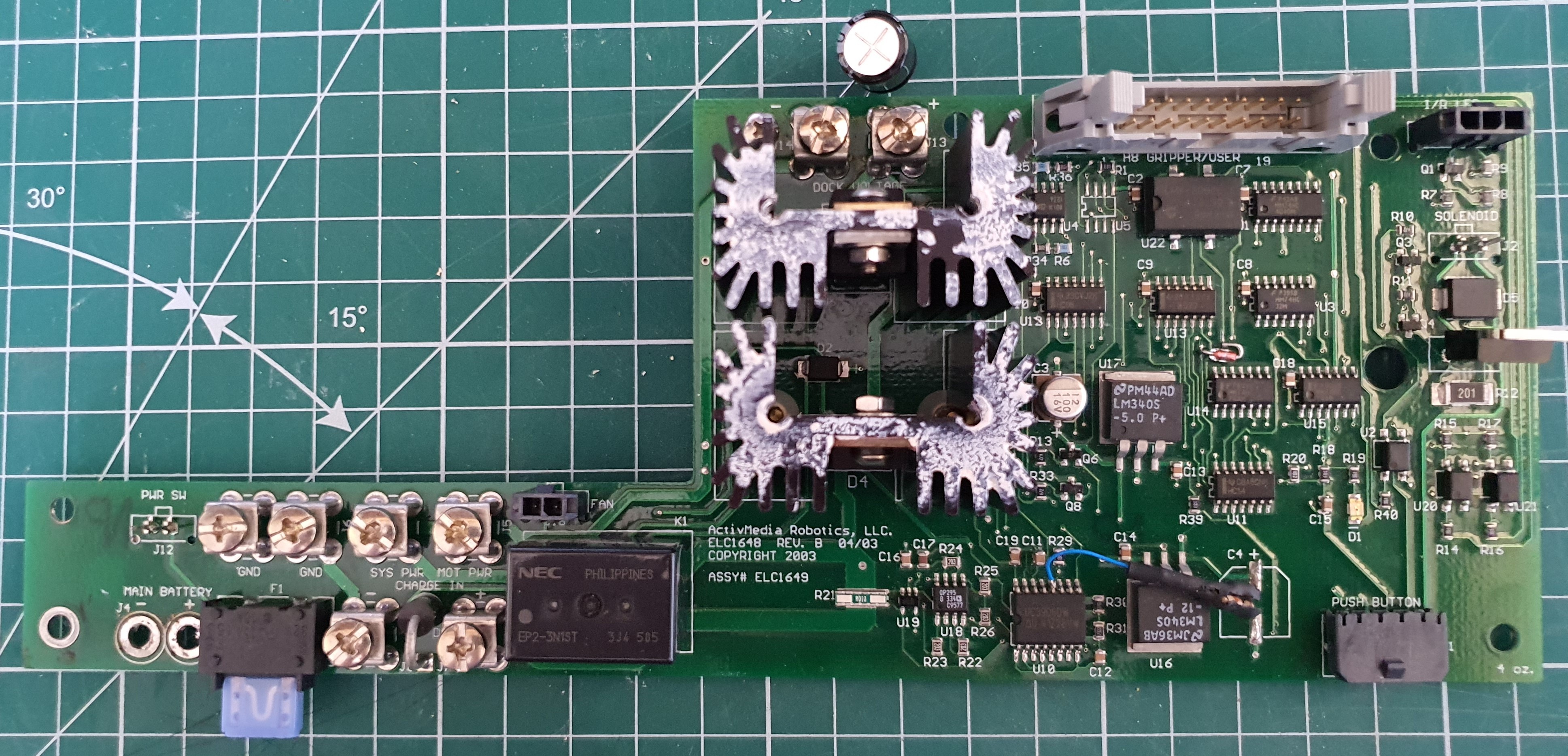
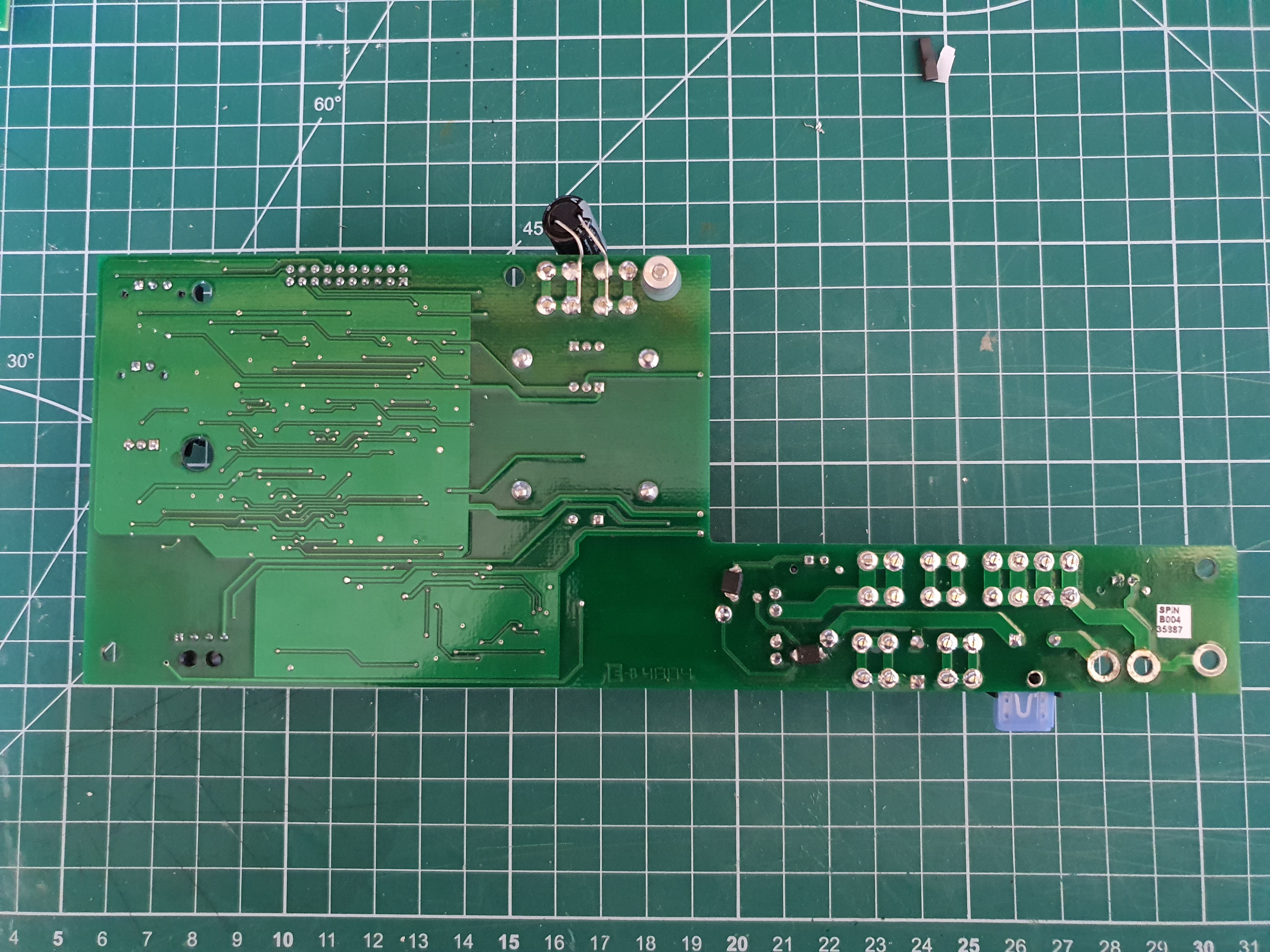
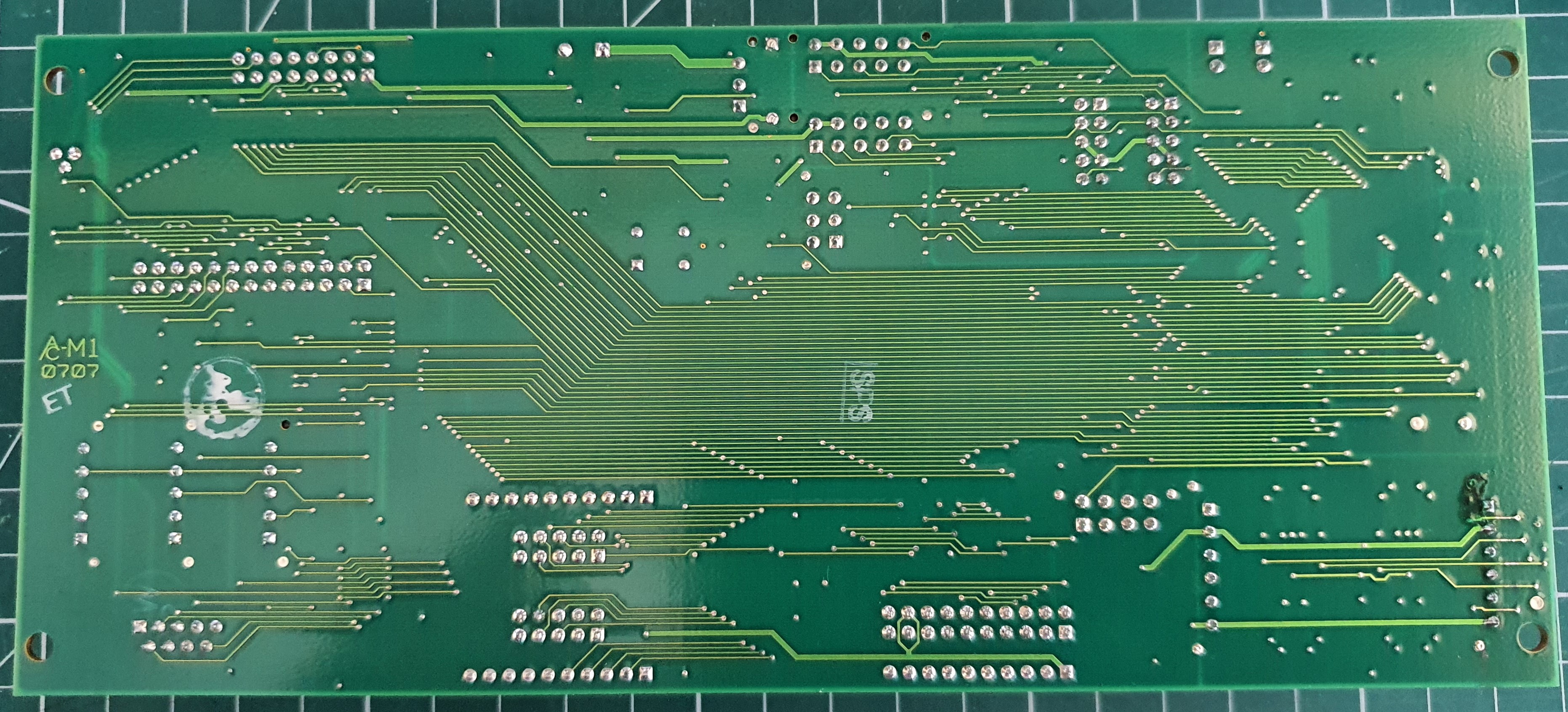
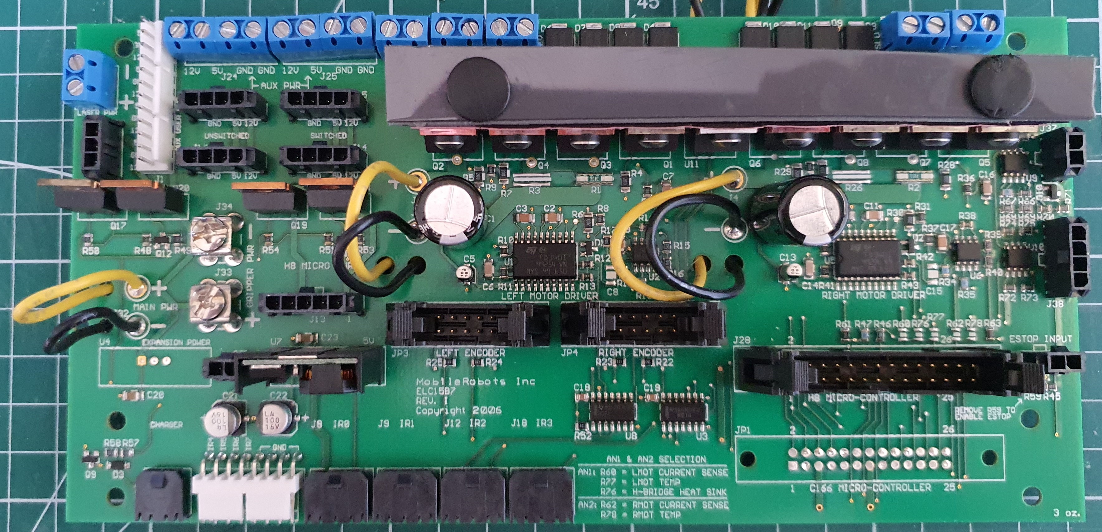 Motor Board - Top
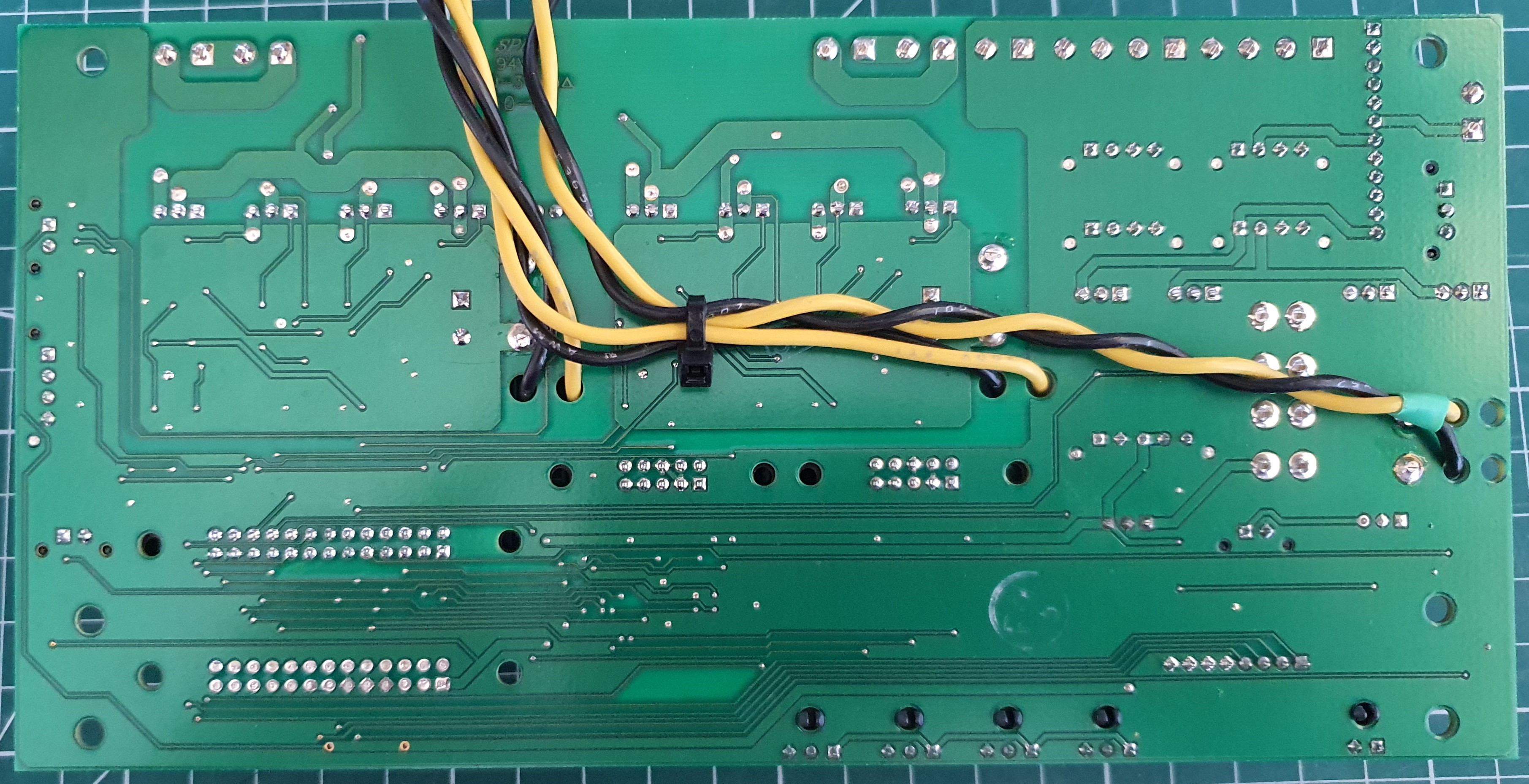

 cyplesma
 Nikolaj Andersson Nielsen
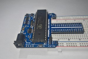
 Daniel Garcia
You know you're living in the future when robots start showing up in e-waste.