-
Frontplate prototype arrived
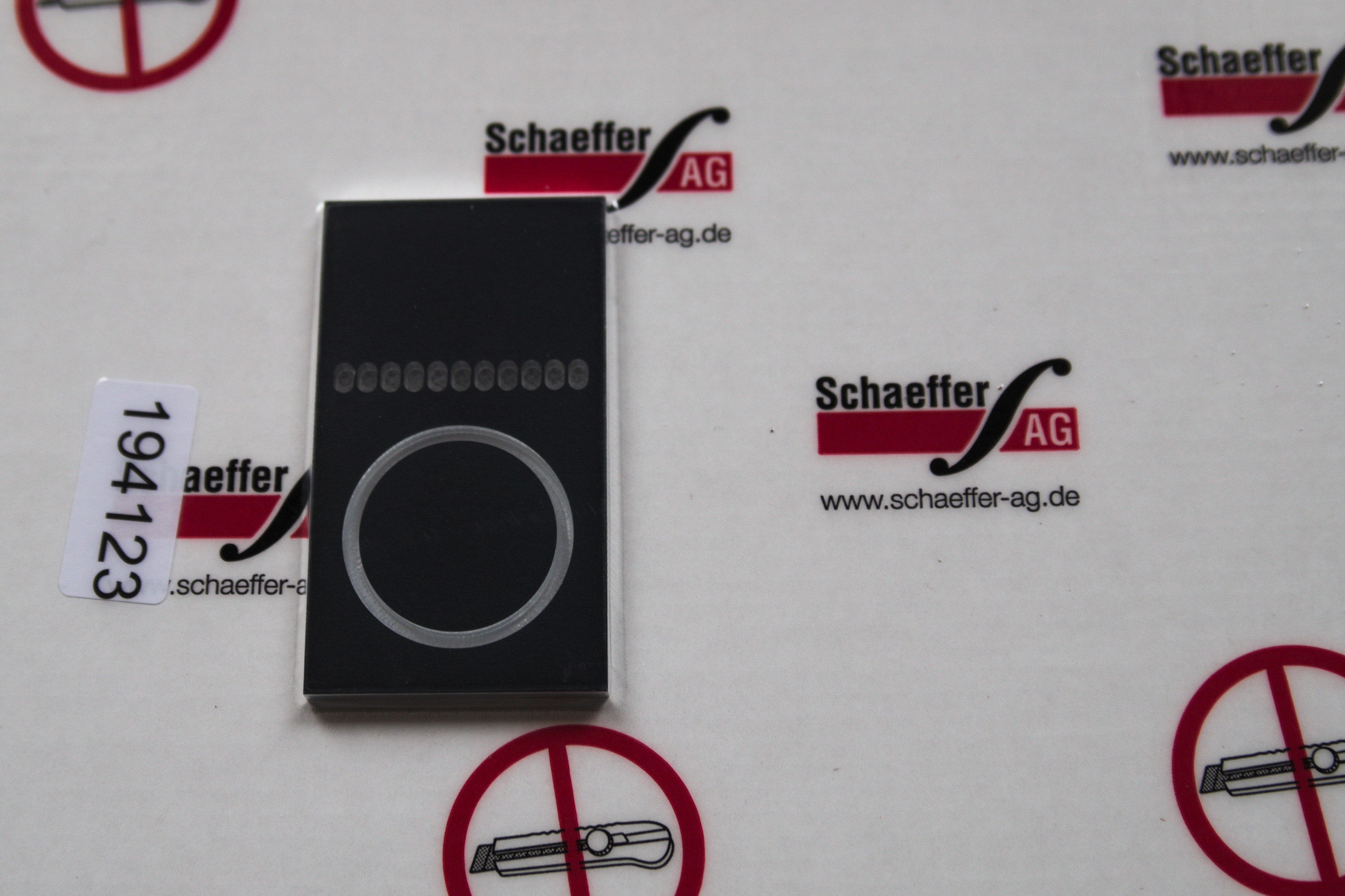
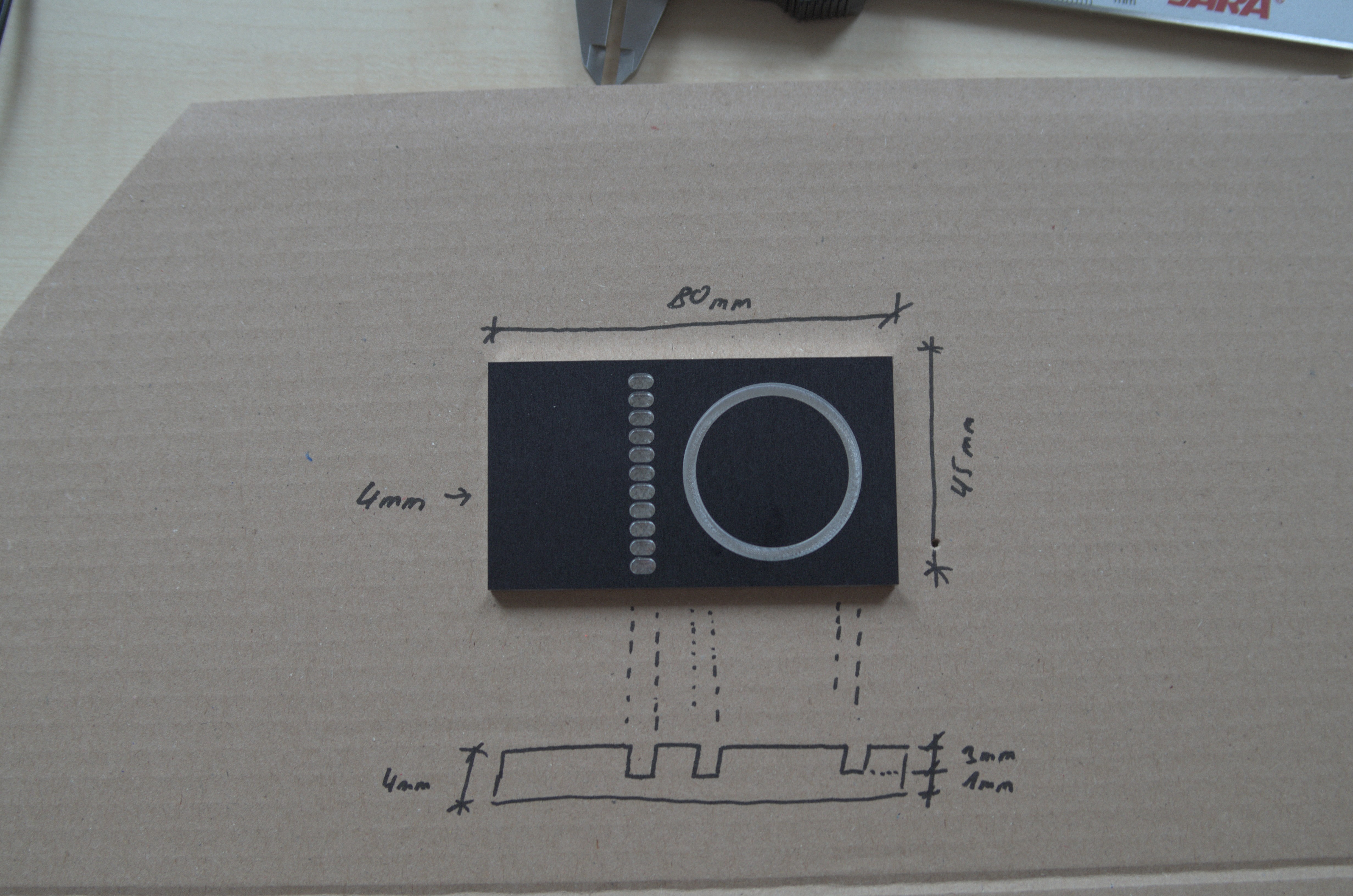
11/09/2016 at 17:51 • 0 commentsToday the milled piece of aluminium, which will be my prototype for the front plate, arrived. It measures 45 x 80 x 4 mm³. I'll test how i can mount the leds, seal the holes with epoxy and so on.
![]()
![]()
The ring on the right side will be the back illumination for the knob. The inner diameter is 30mm, the outer diamter 35mm, which results in an 2.5mm wide slot. No idea, how to fit a 3mm led in there :-/ Next time it should be <= 5mm wide.
In the center there are eleven ("Well, it's one louder. Isn't it?") 3 x 5 mm² wide slots, which will act as an analog vu meter. I'm not sure if I would use this, but i'll give it a try.
The space on the left will be used for some custom 3mm and 5mm holes. They will be used as an channel indicator.
I'm still waiting for te leds and the epoxy. I will take some time until I can drill the holes, as i don't own a drill press. Until then i can only mark the holes and play with the TLC59401, which will drive the leds an the front plate.
-
Designing the chassis
11/07/2016 at 20:36 • 0 commentsIt seems, that i like to design my project from the outside to the inside. So i startet to think about possible designs. Using the pictures of the vu meter, some textures, an 3d model of an Marquardt 1812 switch and some Photoshop / Indesign-magic i was able to create a first visualisation of the front cover.
The measurements and the desing are / is based on the modushop chassis Pesante 02PN 2U that includes a front plate which measures 90 * 450 * 10 mm³.
The front plate will be milled by Schaeffer AG, as they provide a good service, a offline design software and are able to process material send in by the customer. To save some money (and to have some fun at the milling machine), only the front face wil be milled there. All holes and all milling on the back side will be done by myself.
Every glowing part will be illuminated by a 3mm blue led. Those leds are mounted from the back. The holes in the front will be filled with 2k epoxy. Let's find out, how to fill those holes without spilling too much epoxy on the surrounding :). To practise this, i ordered an example piece which will be shipped this week.
As an extra feature, the rotary encoder knob will be back illuminated. It will be possible to adress every single led with an PWM signal. So its possible to add different effects like "breathing" or some "position informations" e.g.: If you're on the top end of the menu, all left leds will light up. If you're on an option in the center, the top leds will light up, and so on.
As I'm not 100% percent shure about the placement of any element, I need to try out some more pssible combinations.
![]()
-
vu meter dimensions
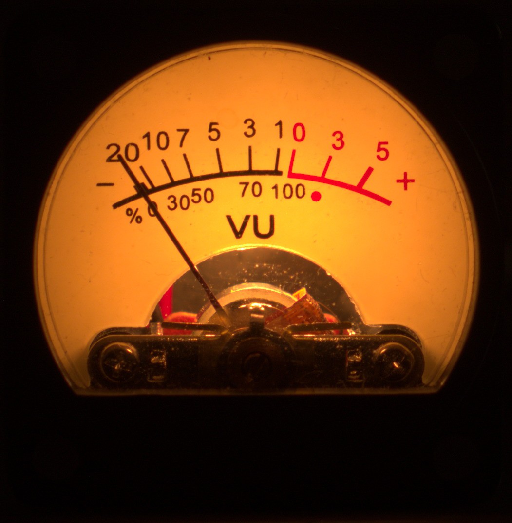
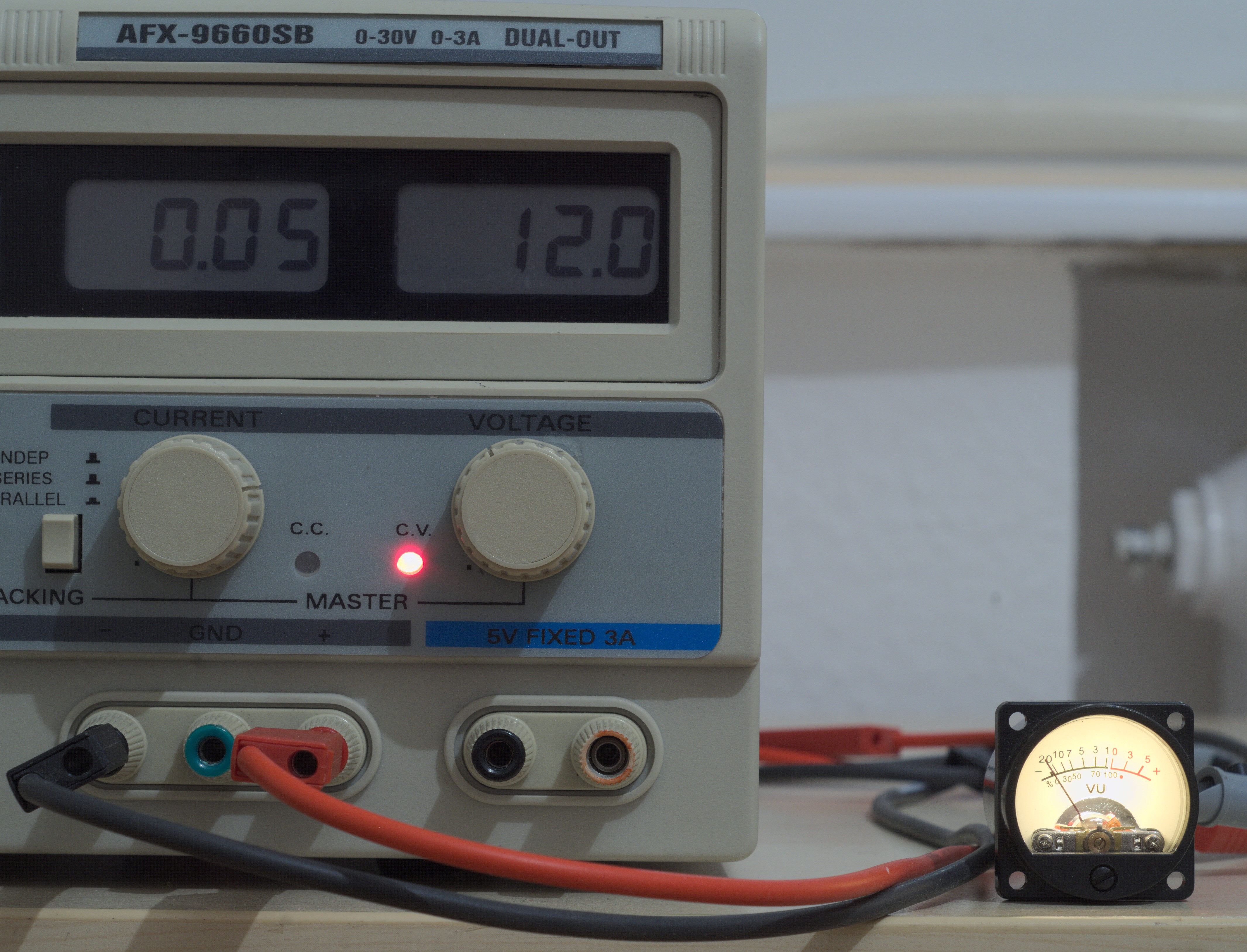
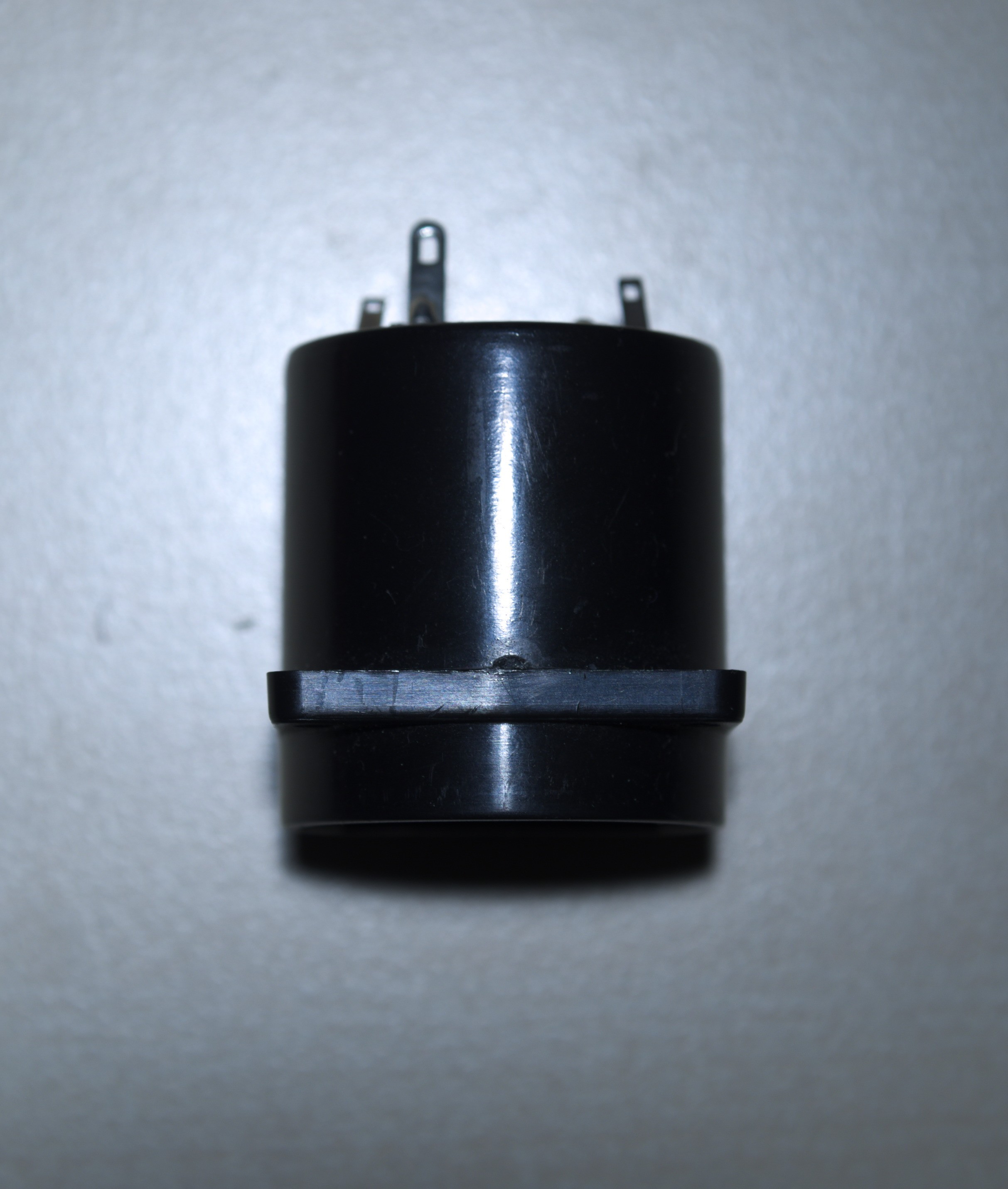
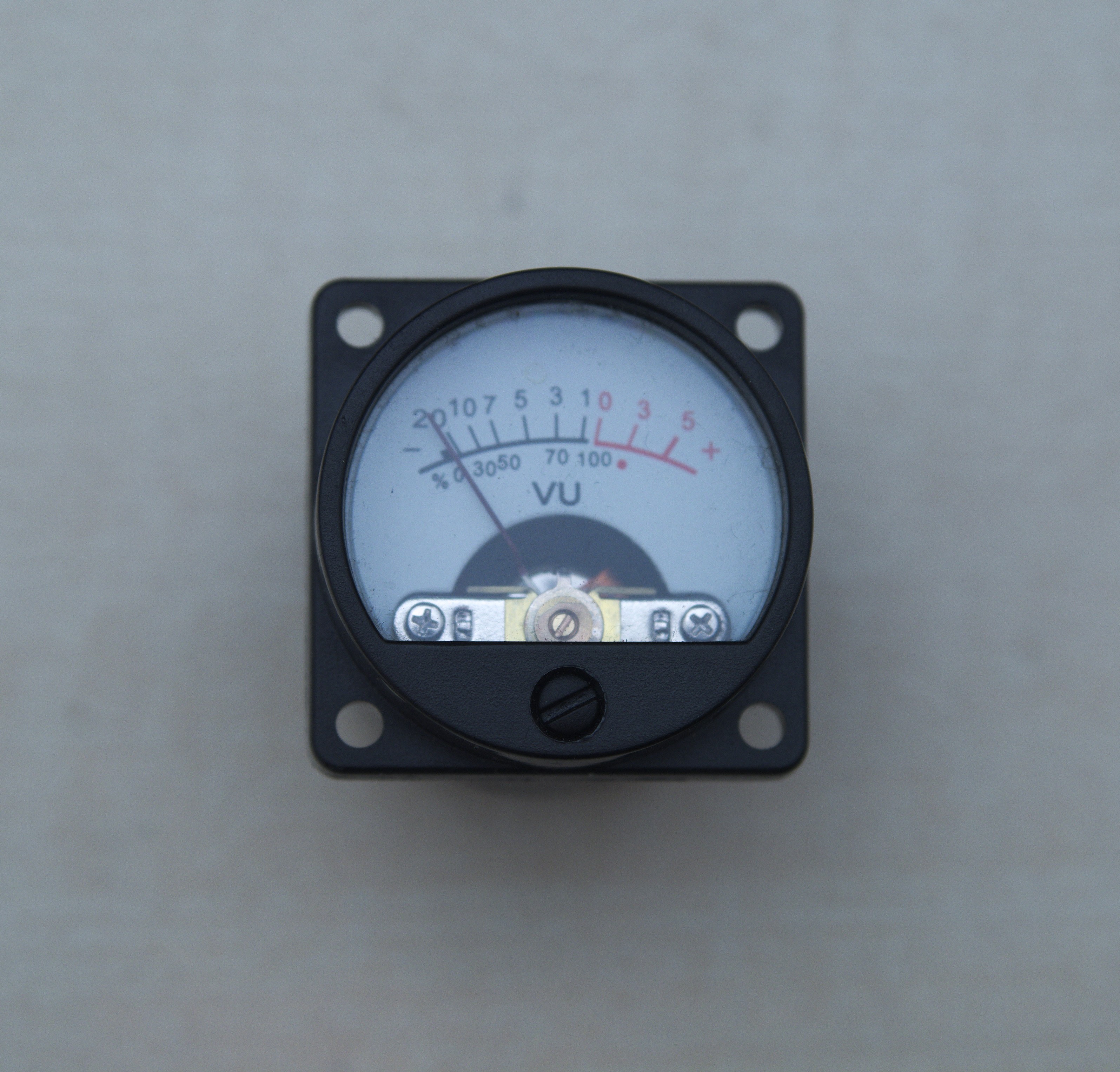
11/03/2016 at 20:54 • 0 commentsToday i took some measurements and photos of the vu meters as a basis to design the front panel, which will be designed in the next step. Those vu meters have at total length of 36.4mm. The first round part is 7mm long, followed by a 3.8mm long square part. The round parts have a diameter of 33.9mm. The square part has a side length of 35mm. The four holes have a diameter of 3.2mm and are 27.8mm away from each other (center of the hole).
The background illumination works well at 12Volt, consuming 50mA.
![]()
![]()
![]()
![]()
PGA2311 DIY Preamp
Let's build a preamp around the PGA2311, some relais, an Atmega and some more parts
 MughtyWinky