 Mitsuru Yamada
1. Hardware configuration
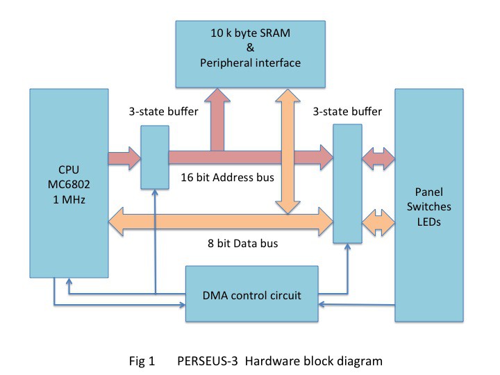
Figure 1 shows the hardware configuration. When CPU is performing instructions, CPU accesses memory devices and peripherals. When you are programming, CPU is separated from bus lines by a Direct Memory Access (DMA) circuits and switches and LEDs on the panel are connected to memory devices directly. The schematic is shown in the attachment file PERSEUS-3_schematic_1.pdf.
2. CPU
I chose the Motorola’s MC6802 as the CPU for this computer because I had machine language development experience with this CPU in 1980 and the ease of making DMA circuits. The MC6802 has the same instructions as the popular MC6800, but in the halt state, the address bus does not go to high impedance and remains outputting the next executable address. This is inconvenient for normal DMA circuit design, but it is suitable for displaying the running address on LEDs.
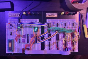
3. Memory
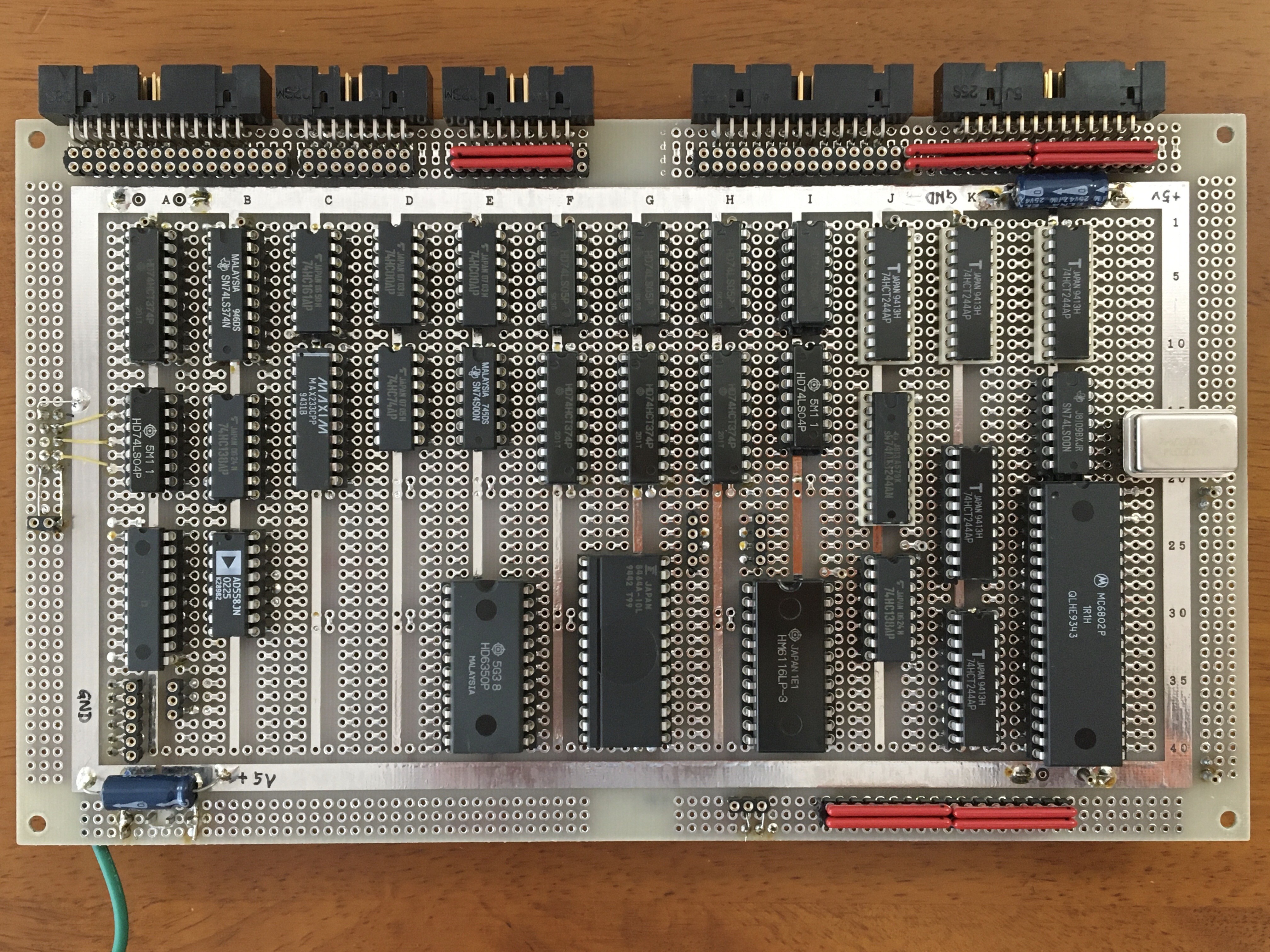
The memory devices are one 16 k bit SRAM (HM6116LP-3) and one 64 k bit SRAM (6264A-10L). The total memory capacity is 10 k byte. Both devices are backuped by 3.6 V, 70 mA h NiMH battery. The battery has a trickle charge. The 2 k byte area by HM6116 including system vector addresses has a write mask switch. The interpreter is installed to this area. Making the write protect switch writable and then you will input the program. Then making the write protect switch write-disable and then you will run the program. This way, the program will not break if it runs out of control. A photo of the main board is shown below.
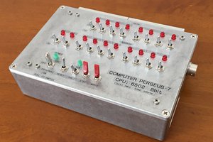
4. Panel switches and LEDs
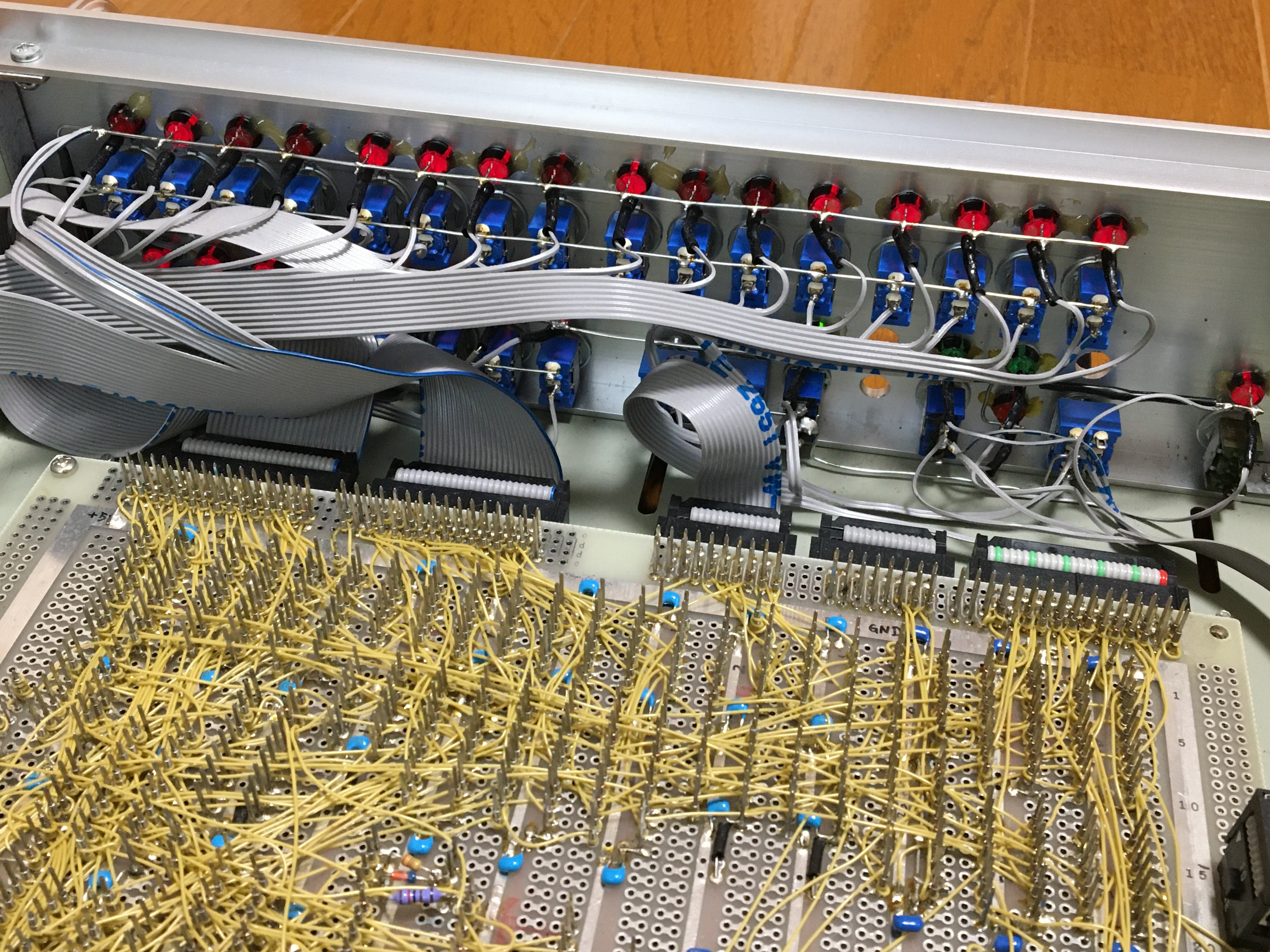
In this computer you enter the programs with switches on the panel. Sixteen address switches are connected to address bus though 3-state buffers (74HC244). Eight data switches are also connected to data bus though 3-state buffers (74HC244). The DMA circuit controls the 3-state buffers. In the serial interface, there are LEDs on the transmit/receive signals so that you can directly recognize the communication status. One bit of the parallel interface is also equipped with a switch and an LED to make it easy to understand the operation of the interface.
5. Debugging by instruction one by one
When the RUN/HALT switch on the panel is set to the halt side, the HALT input signal of the CPU goes to a low level, the CPU stops running. The address LEDs points to the next execution address of the stopped instruction. The memory address bus and data bus are connected to the switches by a DMA circuit. The data display LEDs display the memory data value of the address that the address switches are pointing to. Now, when the write switch is pressed, the value of the data switches is written to the memory and the LED display changes to the written value.
Press the step switch and the CPU will execute one instruction and stop. The correct progress of the program can be seen in the address LED display. When the switch is set to the RUN side, the CPU will start continuous execution from the stop position.
6. Peripherals
The computer has an RS-232C serial interface and an 8bit parallel input/output interface. As a serial interface, Asynchronous Communication Interface Adapter (ACIA) MC6850 (HD6350 Hitachi) is used. The parallel interface is configured with standard logic 74LS374,74HCT374. The computer also has an analog input/output interface. As an analog input, 8bit A/D converter (AD7820) and as an analog output, 8bit D/A converter (AD558JN) is used. The dynamic range is 0v to 2.5V. This is to experiment with analog signal processing.
7. Build
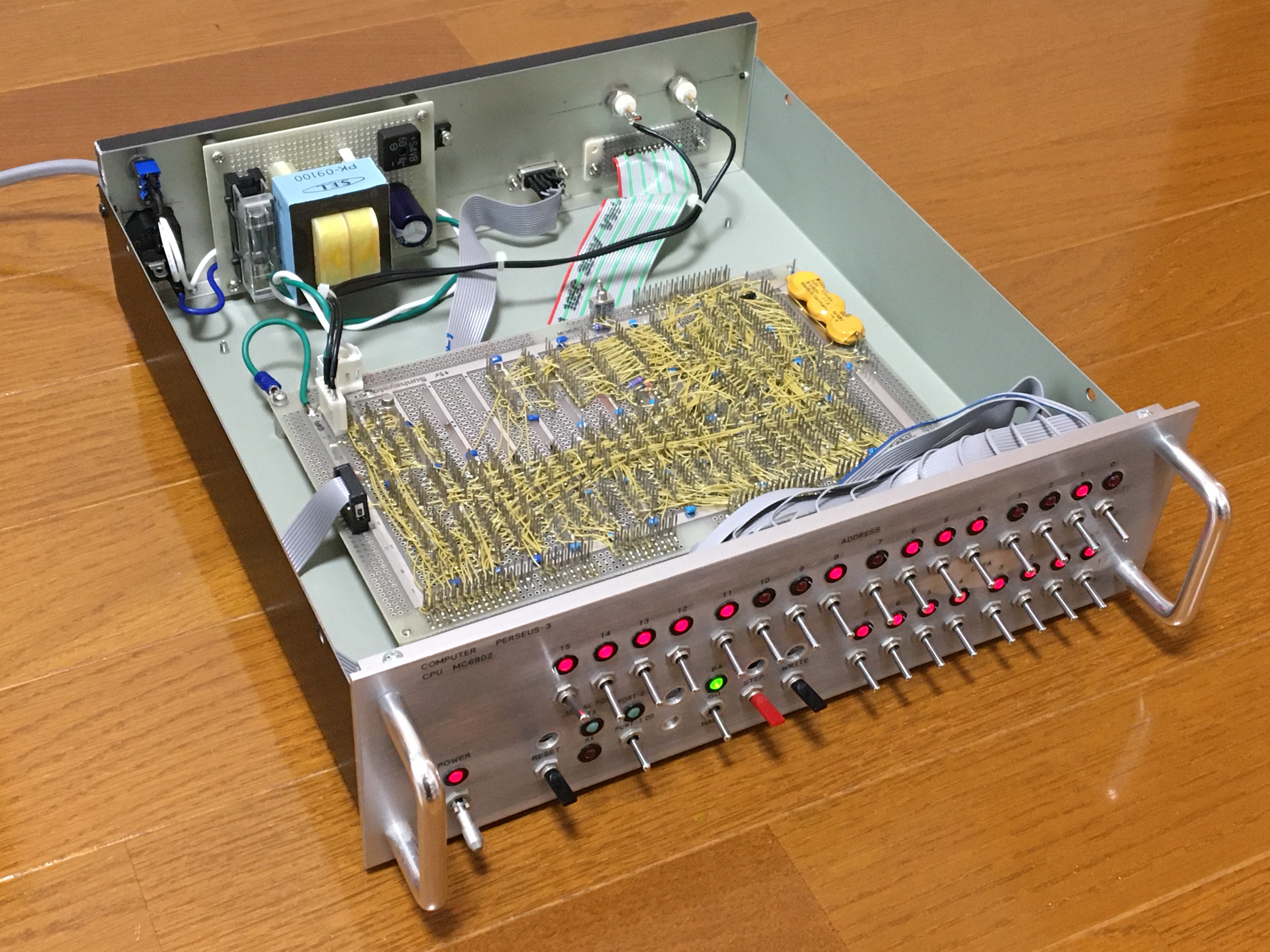
The computer uses a 30 cm x 30 cm x 9 cm steel enclosure but the panel is made of aluminum. This enclosure was for making to self-made audio amplifier. The 5V,1A power supply using transformer and regulator IC 7805 is mounted at the rear of the enclosure. AC power input is 100V. Wiring on a universal board is wire wrapping.
8. A tiny interpreter language
I made tiny 16 bits integer interpreter language...
Read more »


 Tim Ryan
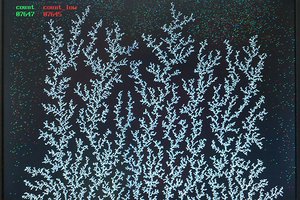
 Bruce Land
 Julián Lell
Really fantastic craftsmanship - truly inspiring! Thanks for sharing this beauty and piece of art here.