-
Boldly Going Forward
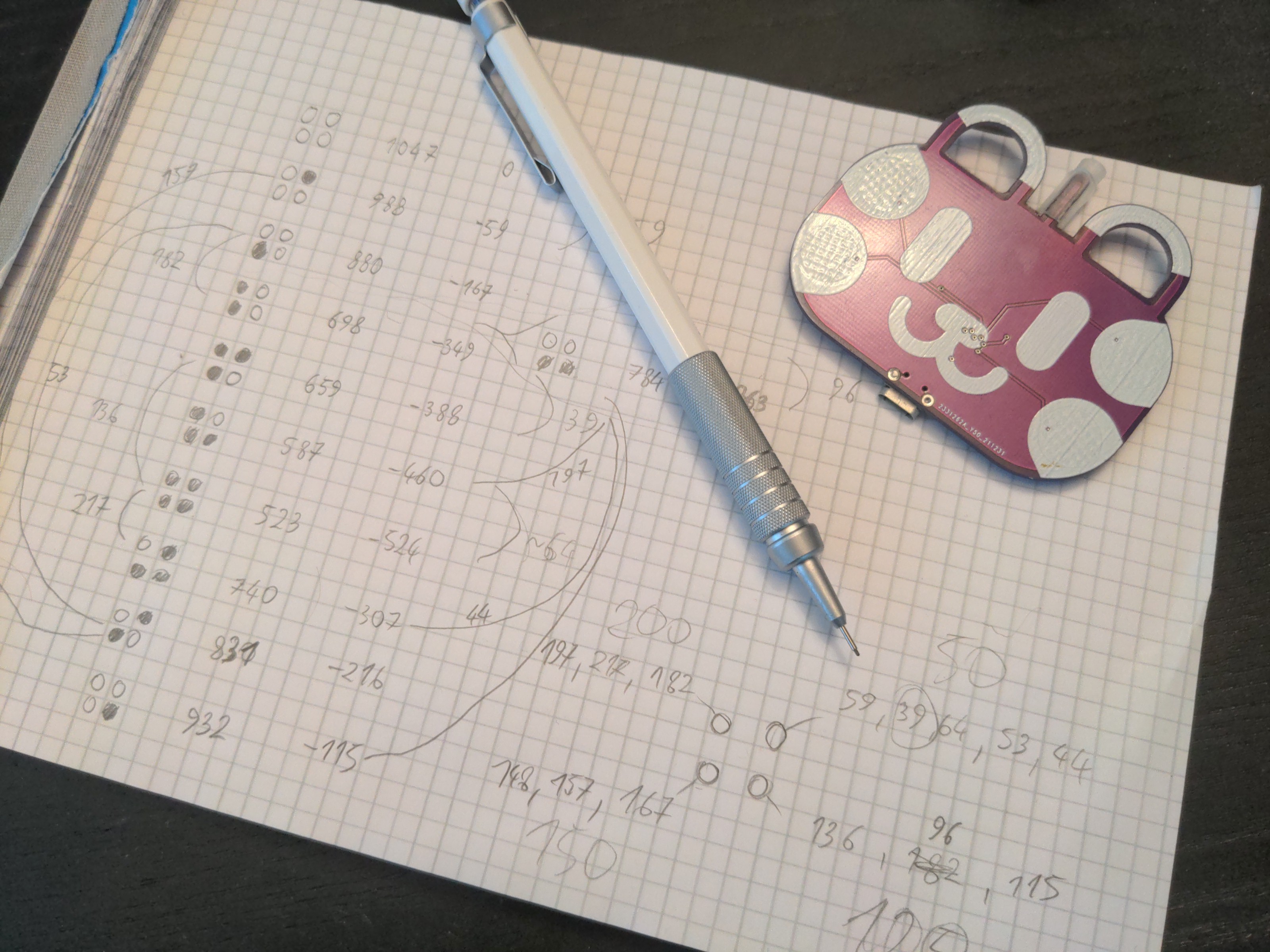
10/23/2022 at 21:40 • 0 commentsIt has been some time since I last worked on this project, mostly because the tests now require actually playing some sounds, and that generally annoys people. But I have been home alone this past week, so I managed to push this a little bit forward. First of all, I had to figure out how the holes actually work. So I took the fingering chart, noted the frequencies of the notes, and compared how covering and uncovering of each hole affected the frequency.
![]()
Turns out the frequency is roughly linear to the total surface area of the holes (as helpfully stated by this Wikipedia article), but not quite, as it also depends on the total volume of air and other details. Also, most ocarinas are not really tuned according to equally tempered scale, which is why makes them so interesting — each one has its own unique feel.
So I decided to just go with very rough increments of frequency by 200, 150, 100 and 50 Hz respectively for each of the four holes on the front (ignoring the holes on the back for now), and later I might just "snap" them to the nearest clear note, if that's needed.
Immediately I discovered several problems with the current prototype. Since the traces for the touch pads pass under the speaker, and they are pretty sensitive, the speaker interferes with the touch sensing, giving a weird vibratto effect. Also, the traces for different pads are too close to each other, and it's very easy to touch ones you didn't mean to touch. And finally, the speaker was very quiet.
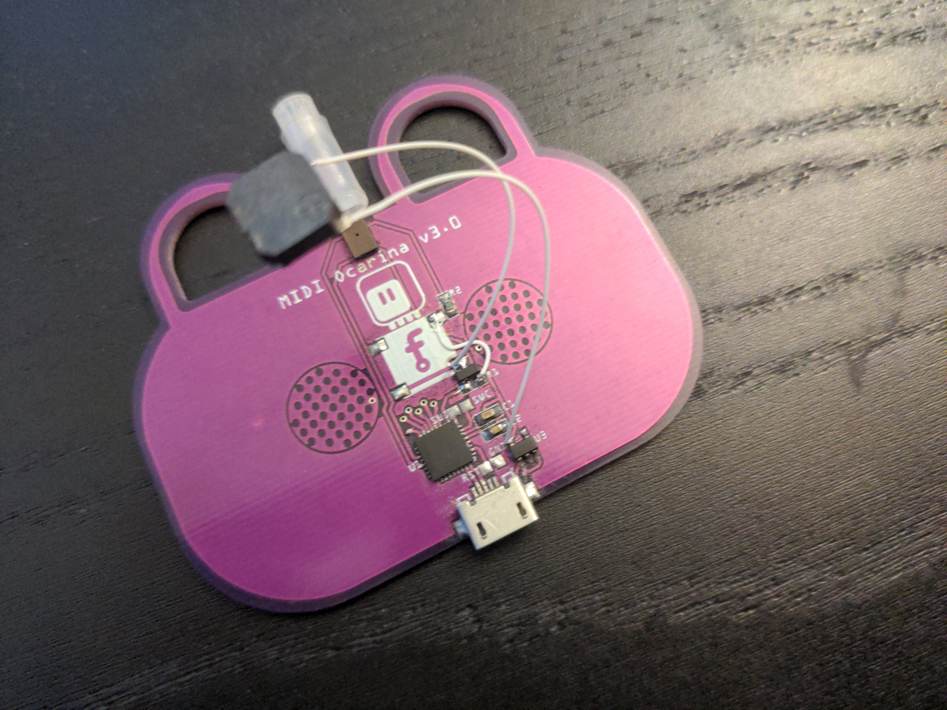
I solved the first and last problem by removing the speaker from the PCB, adding a MOSFET, and making the speaker hang from some wires. Unfortunately the second problem will require a PCB redesign, and I decided to also add a battery holder, so that it can be used without a computer.
I still have one more problem, which is a little bit weird, that I so far failed to diagnose properly. It seems that removing a finger from the pad is detected with some noticeable delay. I'm not entirely sure where that comes from, so I'm holding off on ordering a new PCB yet, in case the fix involves moving the traces again.
![]()
-
Microphone Test
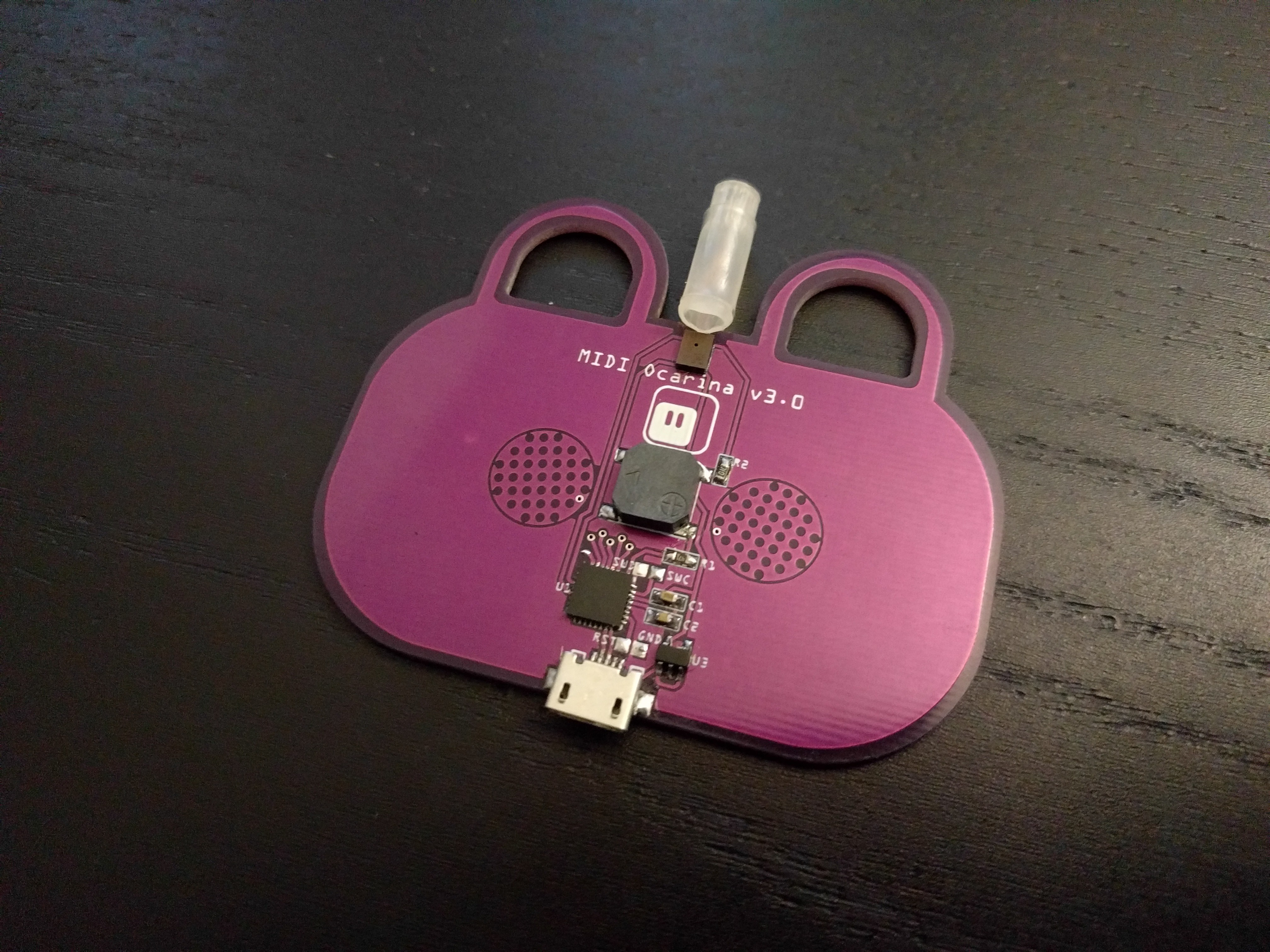
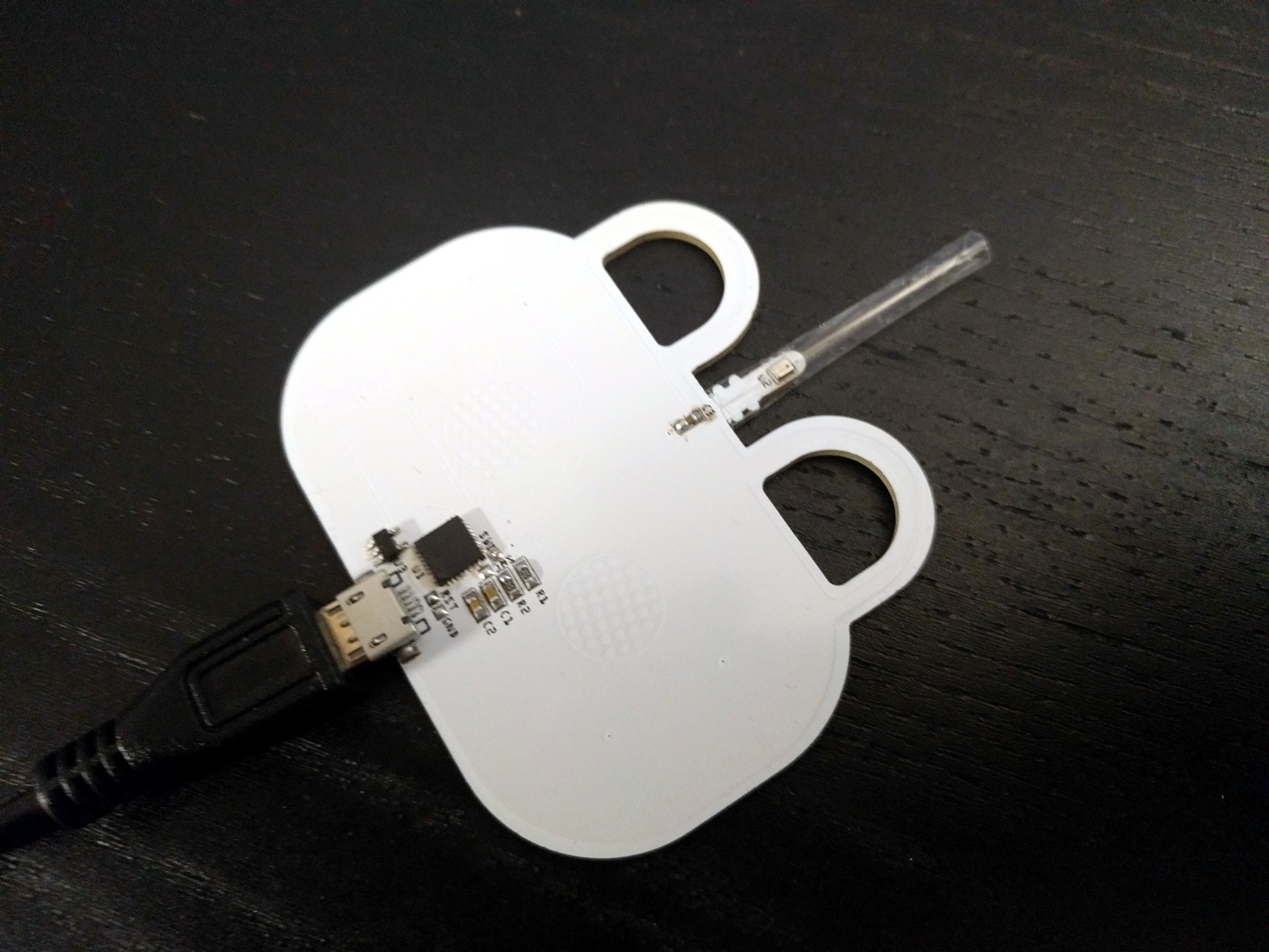
01/15/2022 at 20:50 • 0 commentsThe board has arrived, as well as the microphones. I moved all the components over, and added the microphone and speaker:
![]()
A simple example confirms that the microphone works, and that it's easy to see when it is being blown into:
import board
import array
import audiobusio

mic = audiobusio.PDMIn(board.TX, board.A2, sample_rate=16000, bit_depth=16)
samples = array.array('H', [0] * 160)

while True:
    mic.record(samples, len(samples))
    mean = sum(samples) / len(samples)
    energy = sum(abs(sample - mean) for sample in samples)
    print(energy)
Now to program some output...
-
Designing Second Prototype
12/30/2021 at 20:38 • 0 commentsAfter several more attempts at fixing the pressure sensor in software somehow, I've given up on it, and decided to try a different approach. This time I want to use a microphone placed in the stream of air, and measure the acoustic energy that it picks from the noise of the air rushing by. This should have no problems with a lag or a long recovery time.
To avoid mucking about with analog circuits and amplifiers, I decided to use a PDM microphone — a very simple MEMS device, that takes a clock signal, and gives you back 0/1 pulses that correspond in their frequency to the shape of the waveform — a bit like doing sound output with PWM, only in reverse. Of course CircuitPython already has a audiobusio library that handles it, so it's really easy to get it working: https://learn.adafruit.com/adafruit-pdm-microphone-breakout/circuitpython
![]()
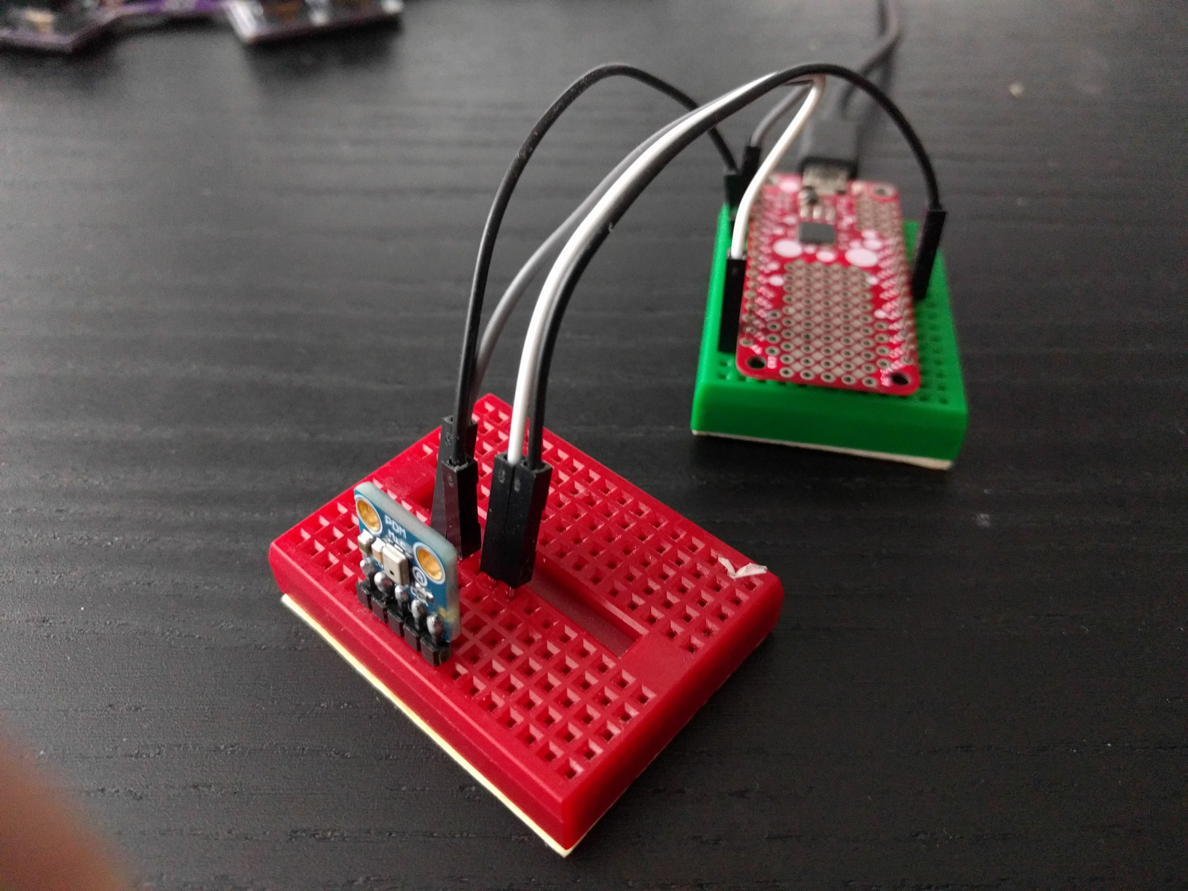
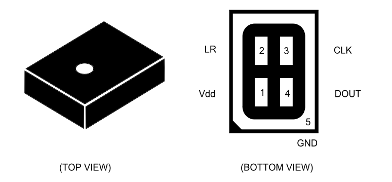
After a test with a module on a breadborad to see if it will work well enough and to determine which pins to use, I went ahead and created a PCB for the new version. I had a moment of doubt when it came to creating the footprint, as the datasheet shows something like this:
![]()
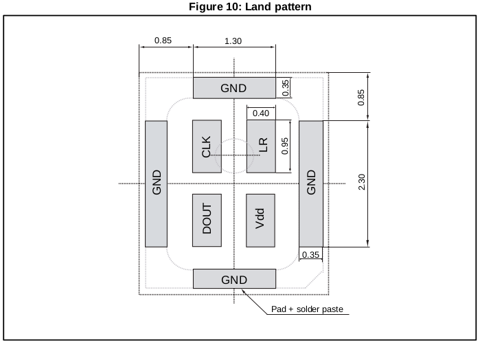
You see, there is no way to route the traces to those pads, unless you use some expensive via-in-pad setup. However, a few pages later they show the recommended footprint, which is a bit more reasonable:
![]()
Using this, I created the PCBs and placed the order at JLCPCB. I should be able to continue the experiments in a week or two.
![]()
Oh, I also added a footprint for a cheap piezo speaker, I will see if I can PWM the tones.
-
First Prototype Problems
01/05/2021 at 18:52 • 0 commentsThe PCBs arrived from @JLCPCB today.
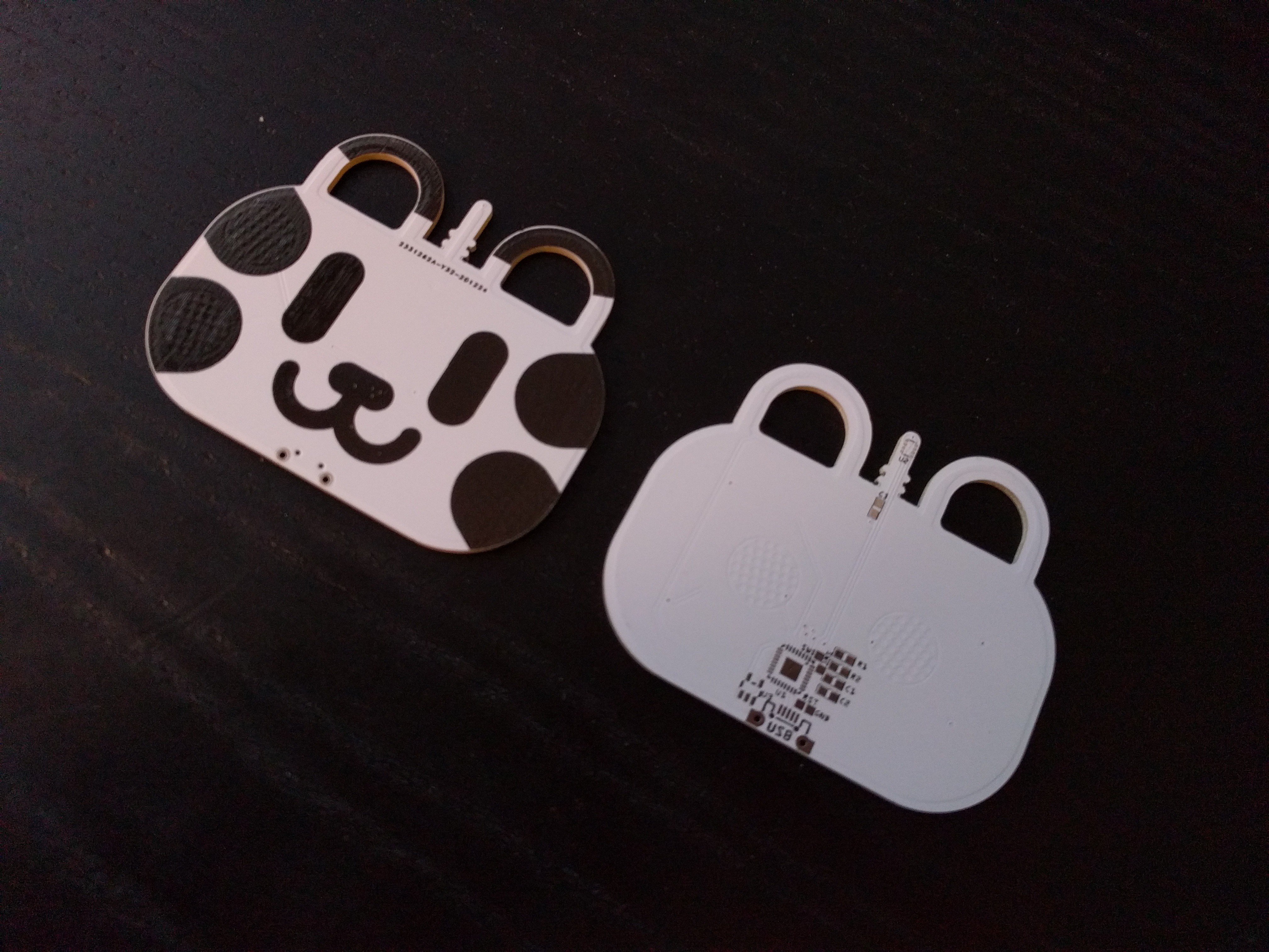
![]()
Assembling one and flashing CircuitPython on it only took a moment, but I had to wait until the evening with programming it.
![]()
I wrote this simple test program that just displays the state of the "holes" and the pressure sensor reading on the USB serial:
import board
import time
import struct
import busio
import touchio


class BMP280:
    _buffer = bytearray(3)

    def __init__(self, i2c, address=0x76):
        self._i2c = i2c
        self._address = address
        self._buffer[0] = 0xf4 # ctrl_meas
        self._buffer[1] = 0b001_001_11
        self._i2c.try_lock()
        self._i2c.writeto(self._address, self._buffer, end=2)

    def get_pressure(self):
        self._buffer[0] = 0xf7
        self._i2c.writeto_then_readfrom(self._address,
            self._buffer, self._buffer,
            out_end=1, in_end=2)
        return struct.unpack_from('>H', self._buffer)[0]

holes = tuple(touchio.TouchIn(pin)
    for pin in (
        board.AREF, board.A0,
        board.A4, board.A6,
        board.A3, board.A1
    )
)
i2c = busio.I2C(scl=board.D6, sda=board.MOSI)
sensor = BMP280(i2c)
base = sensor.get_pressure()
time.sleep(0.1)
base = sensor.get_pressure()
while True:
    print(sensor.get_pressure() - base)
    mask = 0
    for hole in holes:
        mask = (mask << 1) | hole.value
    print(bin(mask))
    time.sleep(0.1)
It's very simple, but it already allowed me to see two potential problems.
First of all, I put traces to the two left-hand "holes" close to the left bottom "hole", which means that you will sometimes touch those traces by mistake, and it's enough to trigger it. The next version will have those traces on the other side of the board, safely shielded with a generous ground fill. Easy.
Second, my initial tests with the sensor were very brief, and I actually converted the value I was reading from the registers wrong, so I didn't notice that the sensor actually "swings back" after I blow into it, and takes a good minute to stabilize back to the ambient pressure. That is a considerable problem if we want to be able to play faster than one note a minute.
For now I'm planning to make it trigger by observing the first derivative — the change in value, if you will — instead of the absolute value read from the sensor. This also solves the problem of the drift that the sensor has, and the challenge of being able to play while riding an elevator. It will complicate the code somewhat, unfortunately. If I can't get it to work, I will probably switch to a microphone.
-
PCBs
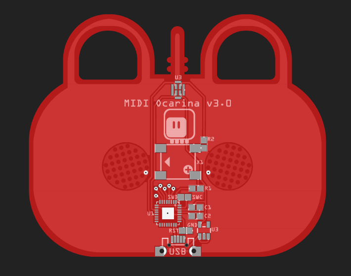
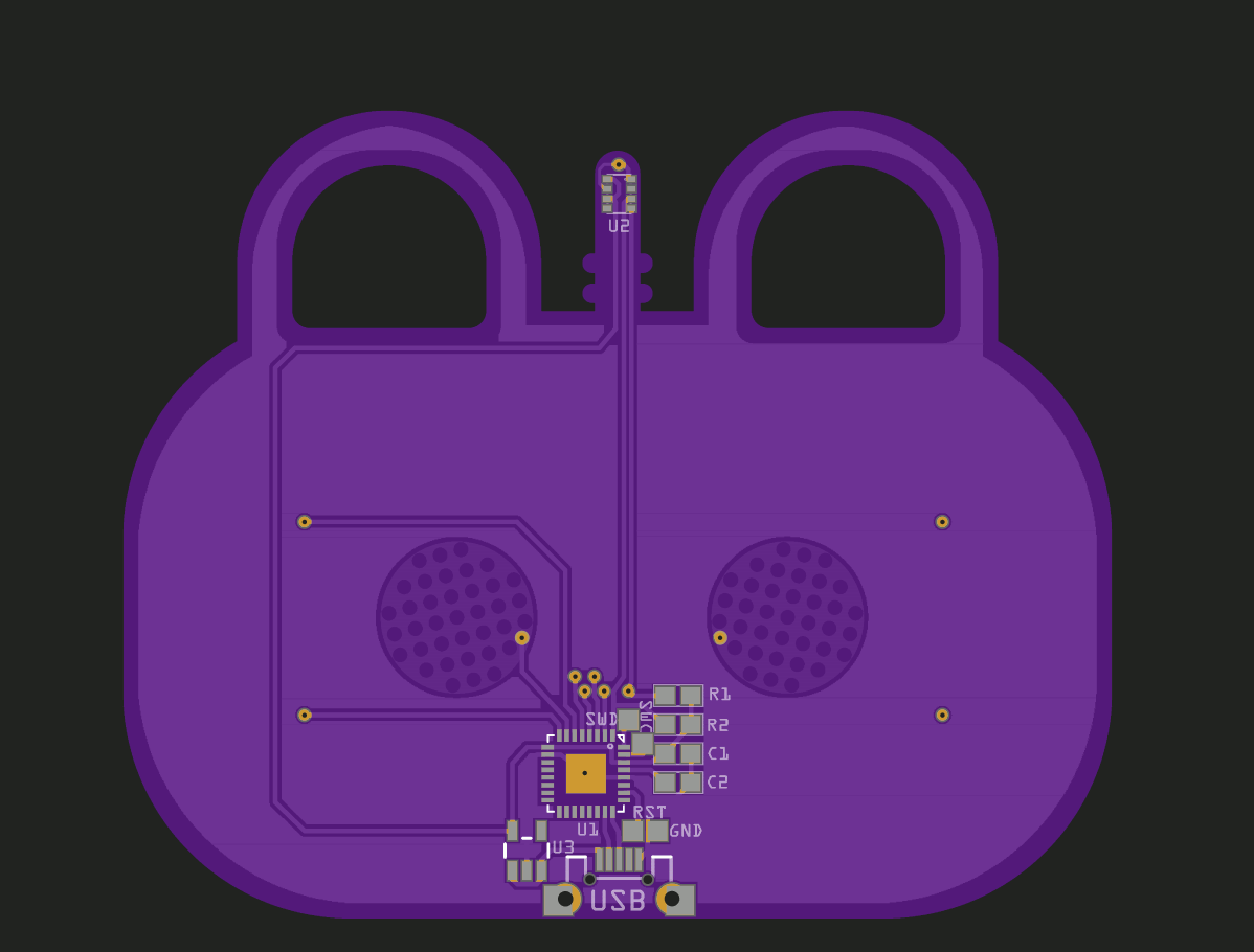
12/23/2020 at 18:45 • 0 commentsI could prototype this project now with some Adafruit Feathers and carboard and wires, using the breakout for the sensor and some tinfoil for the touch pads, but I decided that I'm lazy, and went right into the PCB design step. I came up with this:
![]()
![]()
The "antenna" thing on the top is where you attach a piece of a silicon hose, so that you can easily replace and wash it if you need to. There are also six pads for the "holes" — two on the back, and four on the front. Unfortunately that used up all the touch-capable pins on the SAMD21, so I can't use the DAC pin anymore (it's one of the touch pins), so at least this version is going to be only a MIDI controller, with no audio output of its own. There is also no battery necessary, since it's going to have to be connected to USB anyways, taking power from there. Depending on how well that works, I might find ways of adding more features to it later.
-
What? Why? How?
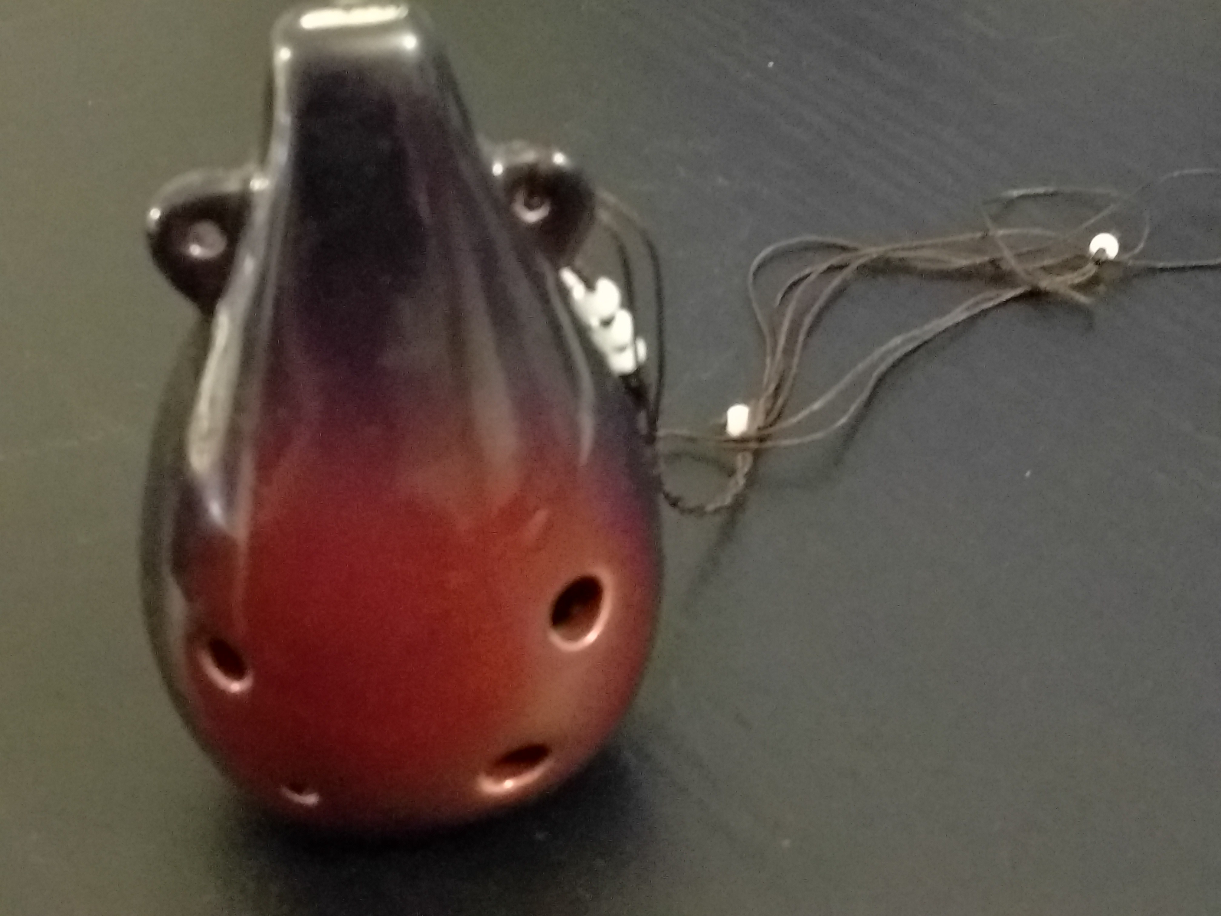
12/22/2020 at 22:39 • 0 commentsOcarina is a pretty unique instrument. It's officially woodwind, even though it usually doesn't contain a single piece of wood, being made out of ceramics (though wooden ocarinas do exist, as well as plastic). It usually has much richer and more interesting sound than all kinds of pipes. And thanks to its appearance in several computer games, you can easily find a lot of game music converted to ocarina tabs. The six-hole ocarina is a specific type of this instrument, that has six holes, and often can be worn on your neck as a pendant.
![]()
There is one big problem I have with my ocarinas, though, and that is probably common to a lot of people who want to practice playing instruments — nobody wants to listen to you practicing, especially if you are pushing your current skill and making a lot of mistakes. For piano players this is a solved problem: just get an electric keyboard and play wearing your headphones! While there are also electronic woodwind instruments, they are usually a bit weird, look nothing like a six-hole ocarina, and use completely different fingering than an ocarina does — so not very good for practice.
So I'm going to build my own. I need a sensor for detecting how hard you are blowing, and six touch-sensitive pads, for detecting which holes are covered and if they are covered whole or just partially (for bending). I'm going to start with a simple USB MIDI output, so that I can use a synth program on my computer to actually make the sounds, but maybe I will also make a standalone version with a headphone jack and a battery — we will see how the project progresses.
The first thing, and probably the hardest, is to decide on the breath sensor. The most obvious solution is a pressure sensor, placed inside some kind of a pipe, so that I can measure the air velocity. If that doesn't work, I can use a variety of other solutions, from a microphone to a heater and temperature sensor.
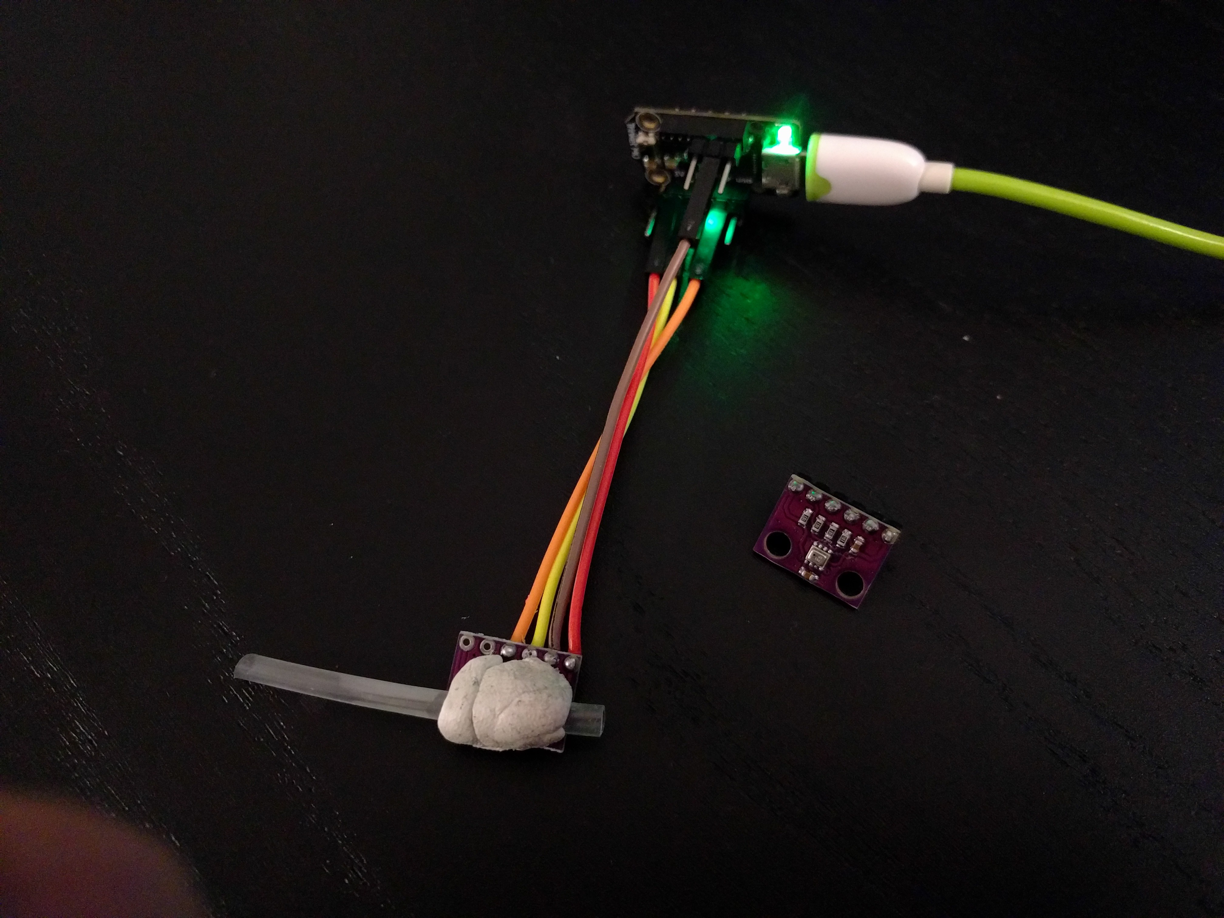
So I took a BMP280 breakout board, blue-tac-ed a piece of straw with a hole on the side on top of it, and tested what readings I can get from it. Initial tests are very promising, I can see a marked increase in the sensor readings while blowing into the straw. More testing is necessary to see how well this behaves, but I'm hopeful.
![]()
 deʃhipu