Close
0%
0%

Rittenhouse 520 Sequencer

Replacement sequencer for a Rittenhouse 520 doorbell

Public Chat
Similar projects worth following
Replacing a worn out electro-mechanical sequencer to keep my door chime in service because I like it.

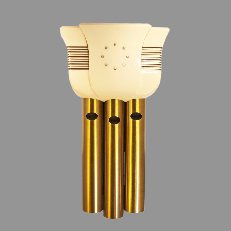
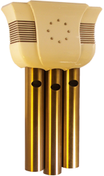
Recently purchased a new to me house, and I was blessed to receive a Rittenhouse 520 door chime from 1950.  Based on hours of research, I found someone who services them, and he came back with this stellar quote:

"Aside from just being non-functional and non-repairiable, they present a fire hazard.  Any multi-note chime that is partially functional has that possibility. The solenoid coils which are intended for momentary operation became little low-powered heating coils when left powered-on indefinitely, due to the normal electrical resistance of the wire.  This heating up can get to the point of begin able to ignite flammable material. Not kidding here- I was once contacted by a fire inspector who explained to me the risk of fire that doorbells in less than perfect working order can present, and in fact have caused numerous house fires."

Because the failure mode has to do with power from the electro-mechanical dashpot (which coincidentally is filled with PCB laden oil) It was necessary to either retire the whole chime, or find a way to replace the dashpot.  Enter everyone's favorite microcontroller: the ESP32. 

I figured that while I'm replacing the fire hazard, I might as well create something I could use for other types of notifications in my house as well, like my basement laundry, or if someone's at my back door as well as the front one.   This project is a journey about me learning more electronics, fixing a fire hazard in my house, and repairing a unique Item that I enjoy looking at and listening to.

x-zip-compressed - 39.58 kB - 02/26/2022 at 17:03

Download

sldprt - 149.96 kB - 02/13/2022 at 19:46

Download

sla - 97.74 kB - 02/13/2022 at 19:46

Download

Rittenhouse 520 sequencer.zip

v0.3 of my attempt at an electronic sequencer.

x-zip-compressed - 2.79 MB - 01/28/2022 at 03:37

Download

Ritt dashpot warning.pdf

Warning I found about the use of the original dashpot and the fire hazard they create.

Adobe Portable Document Format - 109.45 kB - 01/19/2021 at 19:52

Preview
Download

  • 1 × TinyPico Nano ESP32 controller
  • 2 × DF01M Discrete Semiconductors / Diodes and Rectifiers
  • 1 × H11AA1 Opto and Fiber Optic Semiconductors and ICs / Optocouplers and Optoisolators
  • 3 × G3VM-41AY1 Switches and Relays / Solid State Relays
  • 3 × SMB10J20CAHR5G TVS Diode

View all 11 components

  • Finally a working part!

    Michael02/14/2022 at 02:32 0 comments

    After a couple revisions, learning what worked in terms of electronic components, and some seriously rookie mistakes, the v0.3 board that was sent out to OSHPark came back and after soldering on a bunch of parts, I tested it with the doorbell and IT WORKS!   Thank gosh.  Attached is a couple pictures of the test rig I used and the installed sequencer.  Next step is to rewire the doorbell to the button on the front door and test it in place before cleaning everything up and installing it for real.

    Testing Sequencer
    First test of the new circuit board
    Installed Sequencer
    What the new sequencer looks like installed into the doorbell

  • v0.3 Sequencer Sent to fabrication

    Michael01/28/2022 at 03:40 0 comments

    I've gotten  back to work on this project after a long absence.  Finally got tired of people knocking on my door instead of using the doorbell.  Worked through some kinks in the original design, updated and streamlined some of my circuit designs, and removed some superfluous components.  Finally sent out for a prototype board to OSHPark today to see if this design will work better than my previous attempt.  I've uploaded my KiCAD files if anyone else want to take a look or critique.

  • Tracing Doorbell Wiring

    Michael10/30/2021 at 05:05 0 comments

    I've not been working on this project for awhile (the kitchen took precedence).  I've traced the doorbell wiring to make sure that I hook it up to my circuit board correctly:

    white - power wire (screw 1 on the front)

    red - high chime

    brown/red stripe - low chime

    yellow - screw 3 on from (switch wire)

    grey - med chime orange - ground?

    sky blue - to chimes

    brown - power wire (shared with white)

    black - secondary chime wire.

    Dark grey - neutral wire screw 5 on front

    Screw Terminal Labels
    Screw Terminal Labels

  • Learning Circuit Design...by Failure

    Michael04/08/2021 at 15:51 0 comments

    After creating the design for the power supply, the next piece that I needed to create was the interface to ring the chimes.  Because I started without any idea about the intricacies of circuit design, I started testing with a out of the box relay module from Sainsmart:

    https://www.sainsmart.com/products/4-8-channel-5v-2a-solid-state-relay-high-level-trigger

    Hooking this up to a test circuit just to try and ring the bell through a button and connecting the relay to the solenoids...fried the board.  Not understanding inductive loads, I had not given any thought to inductive flyback, and even after frying the Sainsmart board, I went to to fry some more solid state relays before understanding the circuit design necessary to protect against this type of problem.   After coming to this realization,  I added a TVS diode across the relay, and this has fixed the problem for now, but as always I am happy to be criticized to update the circuit and add more protection.  The design of this part of the circuit is below:

  • Researching New Sequencer Power circuit

    Michael01/21/2021 at 17:42 0 comments

    Assuming that someone has tried to do something like this before, Google once again comes to the rescue to find a possible solution for my issue.  after some researching I found this very helpful site that gave me a solid background upon which to create my new sequencer:

    https://lowpowerlab.com/2015/04/13/doorbell-moteino/

    Really easy to follow documentation on how to create a rectifier circuit, as well as a doorbell press detection circuit!  really helpful and simple. So working through what I found I decided that I could probably leverage a lot of what was found in this tutorial, with a few modifications. Because the chime I have requires a constant 16VAC power supply, I already had a power source I could tap into to power the sequencer.    I decided to beef up the rectifier to a full-bridge style chip, I settled on the DF01M for its small packaging and more than adequate output, paired with a 100uF, 50V capacitor to smooth the voltage output.


    This was my first foray into some more semi-serious circuit design, as before this it was incredibly simple stuff.  Once I had all that wired up I added a D24V25F5 buck converter from Pololu to drop the voltage to something the ESP32 could handle, and tested the circuit to make sure the output was at the level I expected.  Amazingly it worked!  A few tweaks to the circuit to add an power LED indicator and we had created a stable power source.

  • Background Research

    Michael01/19/2021 at 19:10 0 comments

    As with every project in the Google age, I started by, well... Googling it.  Apart from the overall design, there exists no identifying marks on the chime, except for some indication of the required voltage etc underneath the volume knob.  So after some creative googling (doorchime 3-note, chime old, chime 1950s , etc.) I was able to find the following reference:


    https://www.electrachime.net/resonator-door-chimes/rittenhouse-beverly-1949/

    Beverly Model – The highly popular model is ideally suited for those people who prefer a chime which takes up less space than the long-tube model. It has a beautifully rich resonant tone, a melody of either 3 or 4 notes. A simple link attachment makes it possible to install the chime to play either a 4-note melody or a shorter 3-note sequence if the owner prefers. The Rittenhouse volume control permits adjusting the tone to any desired level. A shut-off switch also makes it possible to completely turn off the unit if for any reason you do not wish to be disturbed. The rich, ivory plastic housing and the graceful brushed brass tubes combine to provide a beautiful design that is in good taste in any home.

    With the model number in hand, I was able to narrow my Googling, and ran across the delightfully helpful site Knock Doorbells.  Here is where I was able to learn pretty much everything I needed to know not only about how the chime worked, but also about the inherent dangers of this type of chime.  Originally I was just looking to replace parts until it was in working order, but with the knowledge gained from Knock Doorbells, I decided it was worth trying to upgrade it in order to minimize my fire risk and give it some new life.   

View all 6 project logs

  • 1
    Order Materials

    The circuit board was ordered from OSHPark, but I have also ordered PCBs from PCB Way in the past with good results, OSHPark's ordering process is just a bit more intuitive.  You can download the necessary gerber files here.

    Parts can be ordered from all the standard electronics supply houses, Mouser and Digikey being my mainstays.  I have compiled the list of parts you need on the project page here. 

  • 2
    Installation

    The board as it is made has silkscreening on the bottom marking the hookups for each wire attached to the doorbell.  Here is a picture of that:

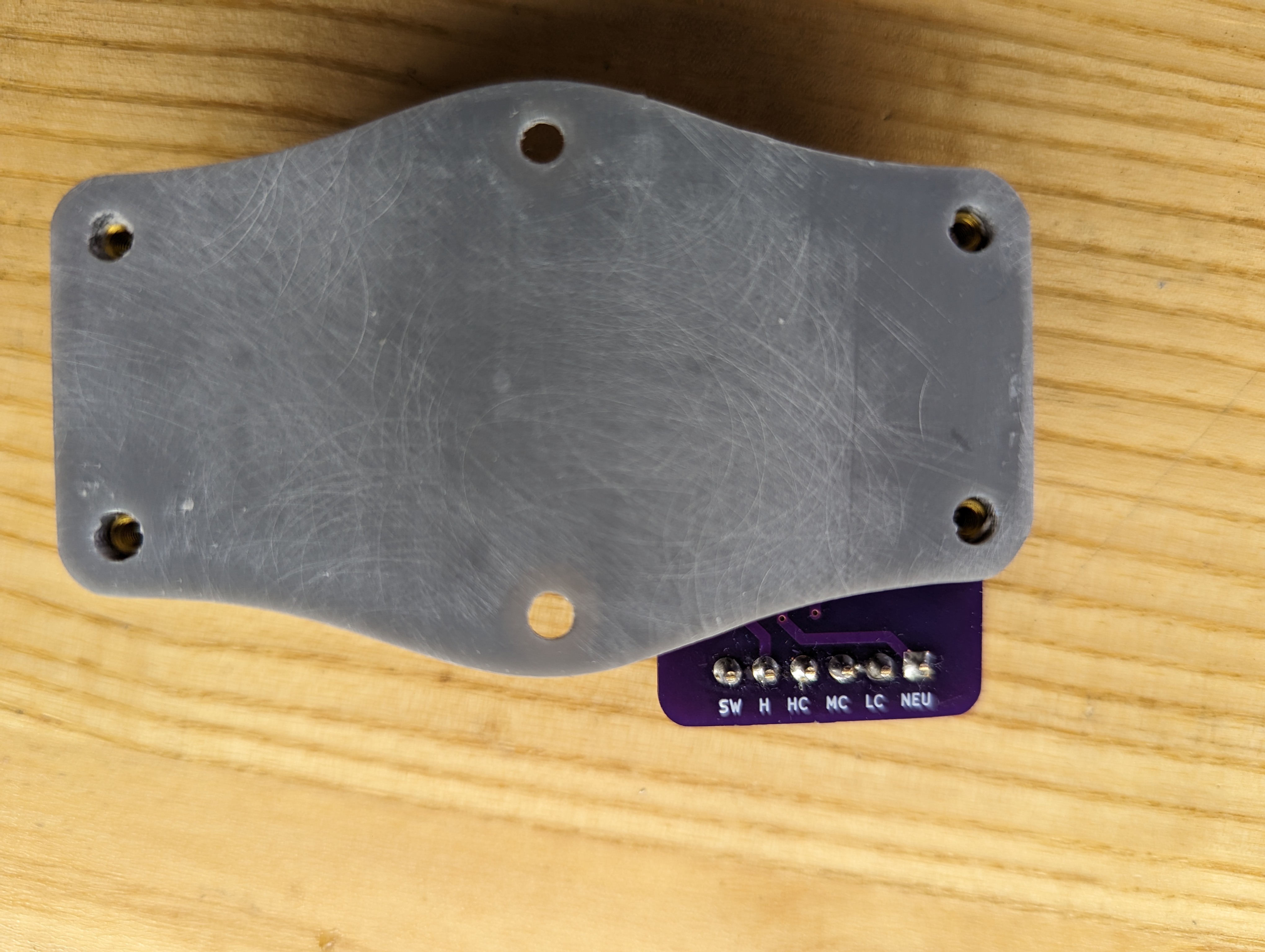
    The notations are as follows:
    SW - Switch hot, this should be connected to the doorbell switch on the terminal
    H - this should be the constant hot from the terminal (connected directly to the transformer)
    HC - High Chime, wire connecting to the high chime
    MC - Mid Chime, wire connecting to the middle chime
    LC - Low Chime, wire connecting to the low chime
    NEU - Connect to the neutral terminal post (connected directly to the neutral wire on the transformer)
  • 3
    Installation of the mount on the doorbell

    On the back of the doorbell, there are six screws that hold the brass resonators onto the mounting plate.  In order to mount the new sequencer, you need to remove the center two screws.  Once removed, center the sequencer mount so the two center holes align with the two screw holes that you just removed.   Use the screws to fasten the sequencer mount to the mounting plate, making sure to catch the screws in their original holes in the resonator.

View all 4 instructions

Enjoy this project?

Share

Discussions

Similar Projects

Does this project spark your interest?

Become a member to follow this project and never miss any updates