This project was developed in partnership with Robô Lúdico Schooland JLCPCB Factory that offers 5 free PCBs of Arduino Compatible Board.
Introduction
Radiofrequency identification or RFID (Radio - Frequency Identification) is a method of automatic identification through radio signals, retrieving, and storing data through RFID tags.
These RFID tags can be placed on animals, objects.
Thus, these labels have many applications such as the non-stop label placed on vehicles, animal identification.
There are 3 types of RFID tags: passive is tags that respond to the signal sent by the transmitter, semi-passive, and active tags that emit the signal itself.
There are currently several ways to control access to a location: using a fingerprint, keypad with a password, and using an RFID system.
In this article, we will learn how to develop an access control system using RFID technology.
This system will consist of the MFRC522 RFID module, a servo motor to open the door, a display to be the system's HMI, and signaling LEDs.
So in this article, we will learn how to develop an access control using an RFID module.
Therefore, through this article you will learn:
- Perform the circuit assembly on the protoboard;
- Understand the functioning of the RFID module;
- Servo motor activation;
- Writing on the LCD display.
Now, we will start the complete presentation of the development of the parking access control system project using the RFID module.
Developing the parking access control system using the RFID Module with Arduino
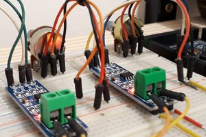
The heart of this project is the RFID module, which consists of a printed circuit board with the MFRC522 integrated circuit and an antenna on the board.
When the board is energized, the module emits a radio frequency signal and when a tag approaches the module, the tag is read, each tag has a different code.
The module is powered by 3.3 V and it uses SPI (Serial Peripheral Interface) communication to communicate with the microcontroller used.
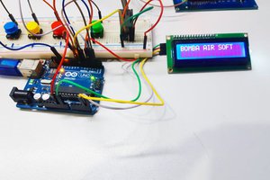
To develop this project the first step is to assemble the circuit in figure 1.

The operation of the circuit is quite simple! The Servo-Motor works as a mechanism for opening and closing the gate. Each time the tag is recognized by the RFID module, the Arduino sends the information to activate or close the gate.
The LCD is used to function as a communication interface with the user.
Next, we'll see how the programming logic for this project works.
The operating logic of the parking system control with Arduino
To program the Arduino Nano we will need the following libraries:
- SPI - Library containing the functions necessary to carry out SPI communication.
- MFRC522 - Library that contains the necessary functions to communicate with the RFID module.
- Servo - Library that contains the necessary functions to start the servo motor.
- Wire - Library containing the necessary functions to carry out I2C communication with the LCD display.
For this project, we'll use the JLCPCB Arduino Compatible printed circuit board presented below.

You can obtain the Arduino JLCPCB compatible PCB for your projects for $2 in your first order with the link: Earn my PCBs Arduino Compatible.
Use the JLC-RECE coupon, earn a $2 off discount, and earn 5 PCBs.
The liquidCrystal_I2C and MFRC522 libraries are not installed in the Arduino IDE, so we will have to install them.
After installing the libraries, close the Arduino IDE and open it again.
The complete code is shown below.
/* * Teste Leitor RFID * tag 1 F1 B103 1F 241 17703 31
F1 B1 03 1F
 tag 2 14 45 29 57 20 69 41 87
14 45 29 57
 */

#include <SPI.h>
#include <MFRC522.h>
#include <Servo.h>
#include <Wire.h>
#include <LiquidCrystal_I2C.h>

Servo myservo ;
LiquidCrystal_I2C lcd (0x27,2,1,0,4,5,6,7,3,POSITIVE);

#define vermelho 4
#define verde 5
#define SS_PIN 10
#define RST_PIN 9

MFRC522 mfrc522 (SS_PIN, RST_PIN);

void...
Read more »
 amr.mostaafaa
 Silícios Lab