 Amey Dahikar
-
1Working
![]()
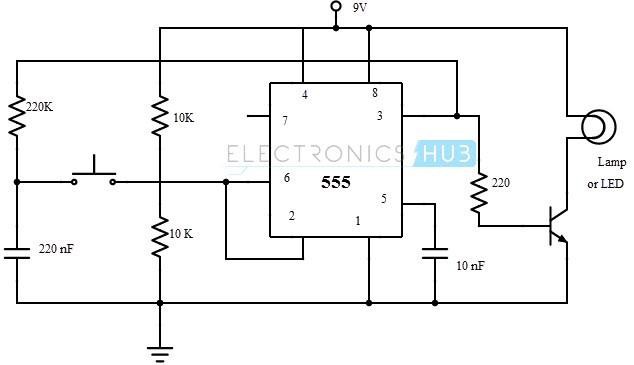
Source :- https://www.electronicshub.org/wp-content/uploads/2015/06/Flip-flop-to-control-LED.jpg
When the output at pin 3 is high, the capacitor C charges through the resistor R1 to the peak value i.e. VCC. When the output at pin 3 is low, the capacitor discharges through the same resistor to 0. In order to switch the output from high to low or low to high, a switch is used at the junction of trigger and threshold pins.
The voltage divider formed by the resistors R2 and R3 will provide a voltage of VCC / 2 at the pins 6 and 2. When the switch is pressed, this voltage is interrupted and triggers the internal flip-flop. This will allow the output to switch between the two states.
-
2CIrcuit Diagram
![]()
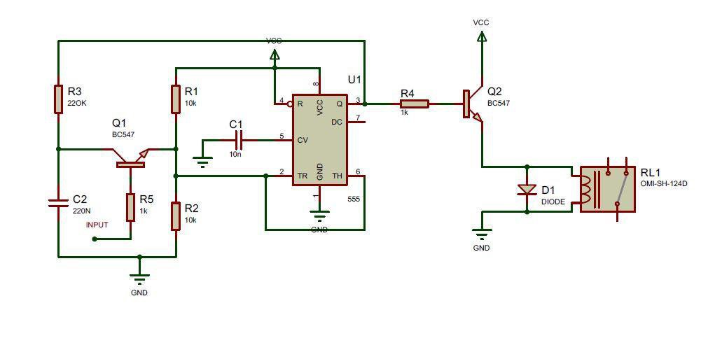
A circuit that acts as a toggle flip-flop is shown below. It is used to light an LED and the LED switches between ON and OFF when the switch is pressed.
So, as I am using IR Sensor Module its give value high or low but I required to connect two pin like a switch, so I decide to use simple bc547(Q1) transistor as a switch as shown in the circuit diagram below. It just work fine in my circuit as high voltage apply to the base of the transistor, current star flowing from collector to base acting as a conductor
-
3Youtune Video
WAVE SWITCH||TOUCH LESS SWITCH USING 555
Basic 555 timer IC and IR sensor project
Discussions
Become a Hackaday.io Member
Create an account to leave a comment. Already have an account? Log In.