mircemk
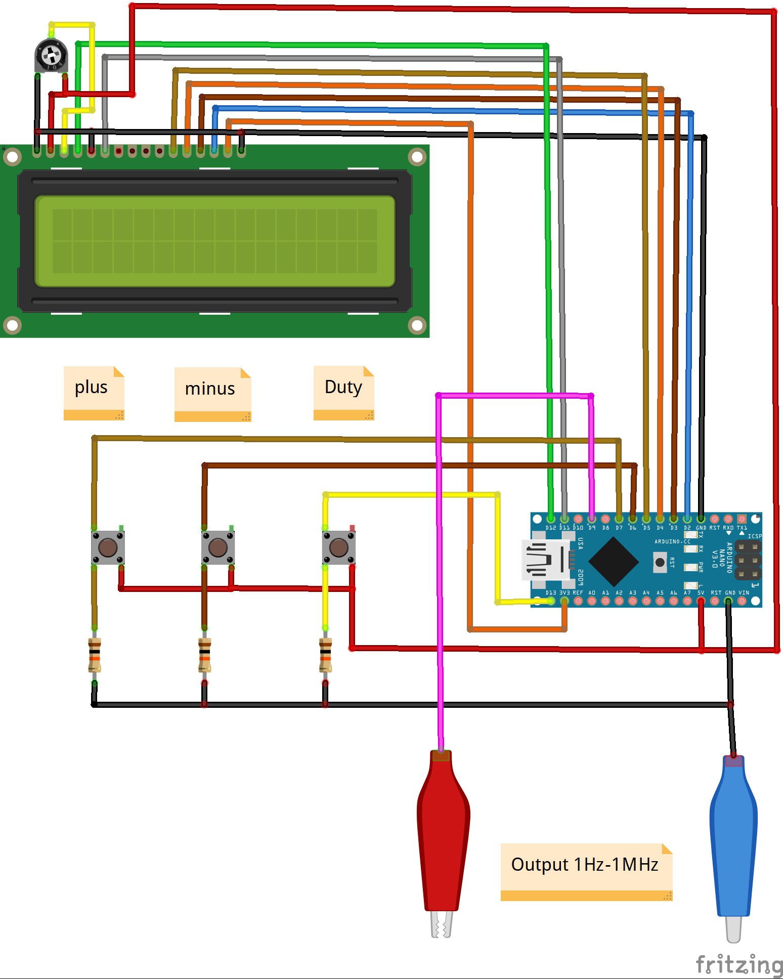
 Device is very simple to build and consist only a few components:
- Arduino nano microcontroller
- LCD Display
- Three pull Up resistors
- and three push buttons
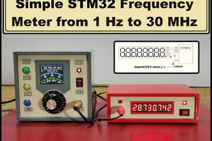
The pulse generator has the ability to adjust the pulse repetition period using the buttons connected to digital inputs 6 and 7 of the Arduino. 13 input pin allows you to adjust the duty cycle. The duration and duty cycle readings are displayed on the first row of the LCD 16 × 2 indicator, and the frequency readings are displayed in the second row. The minimum step for adjusting the pulse repetition period is 1 μs, so the frequency will change discretely, for example, 1 μs is 1 MHz, 2 μs is 500 kHz, 3 μs is 333.333 Hz, and so on, and as the frequency decreases, the smoothness of its adjustment increases. This is quite impractical at higher frequencies but that is the price of simplicity. In one of my previous videos I have described the construction of a similar device but with the help of a specialized DDS chip that does not have these shortcomings and has a much larger range, but is more complex to build
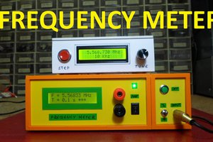
To visualize the output signal I use small single- channel oscilloscope. Finally, the device is mounted in a suitable box, and it is another useful tool in the electronics laboratory.
 Nick Johnson