0%
0%
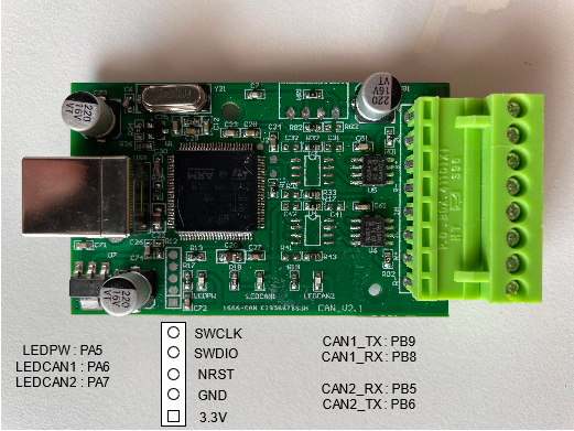
USBCAN-2A Hack
USBCAN-2A is a Chinese CAN Bus Analyzer running with a stm32. My goal : flash the unit with my own program
 F Caminade
Become a Hackaday.io member
Already have an account? Log in.
Just one more thing
To make the experience fit your profile, pick a username and tell us what interests you.
Pick an awesome username
hackaday.io/
Your profile's URL: hackaday.io/username. Max 25 alphanumeric characters.
Pick a few interests
Projects that share your interests
People that share your interests


 Just4Fun
 Electroniclovers123
 J3TTBlack88
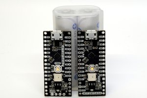
 andriy.malyshenko