Ben Gruver
-
Steel sheets and static bases
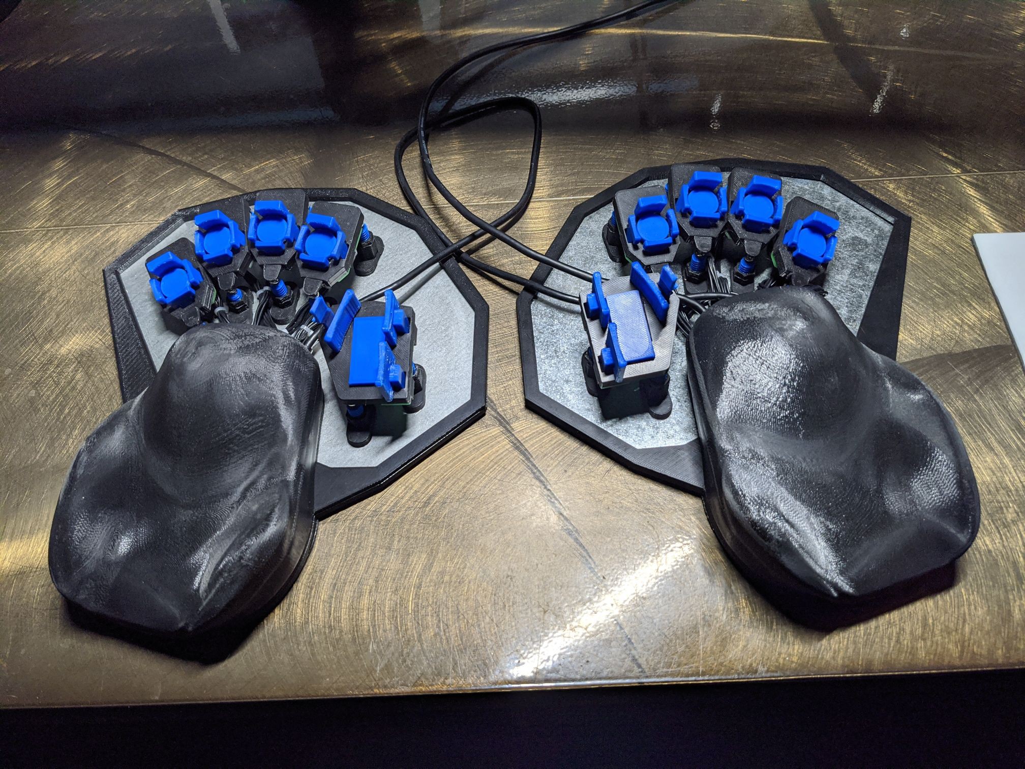
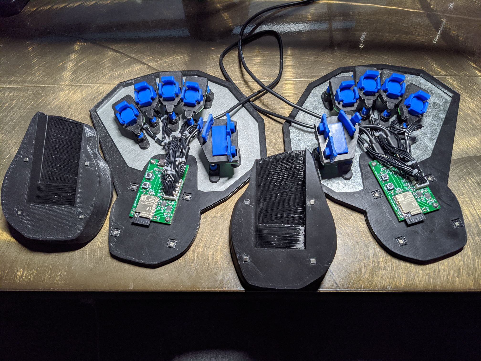
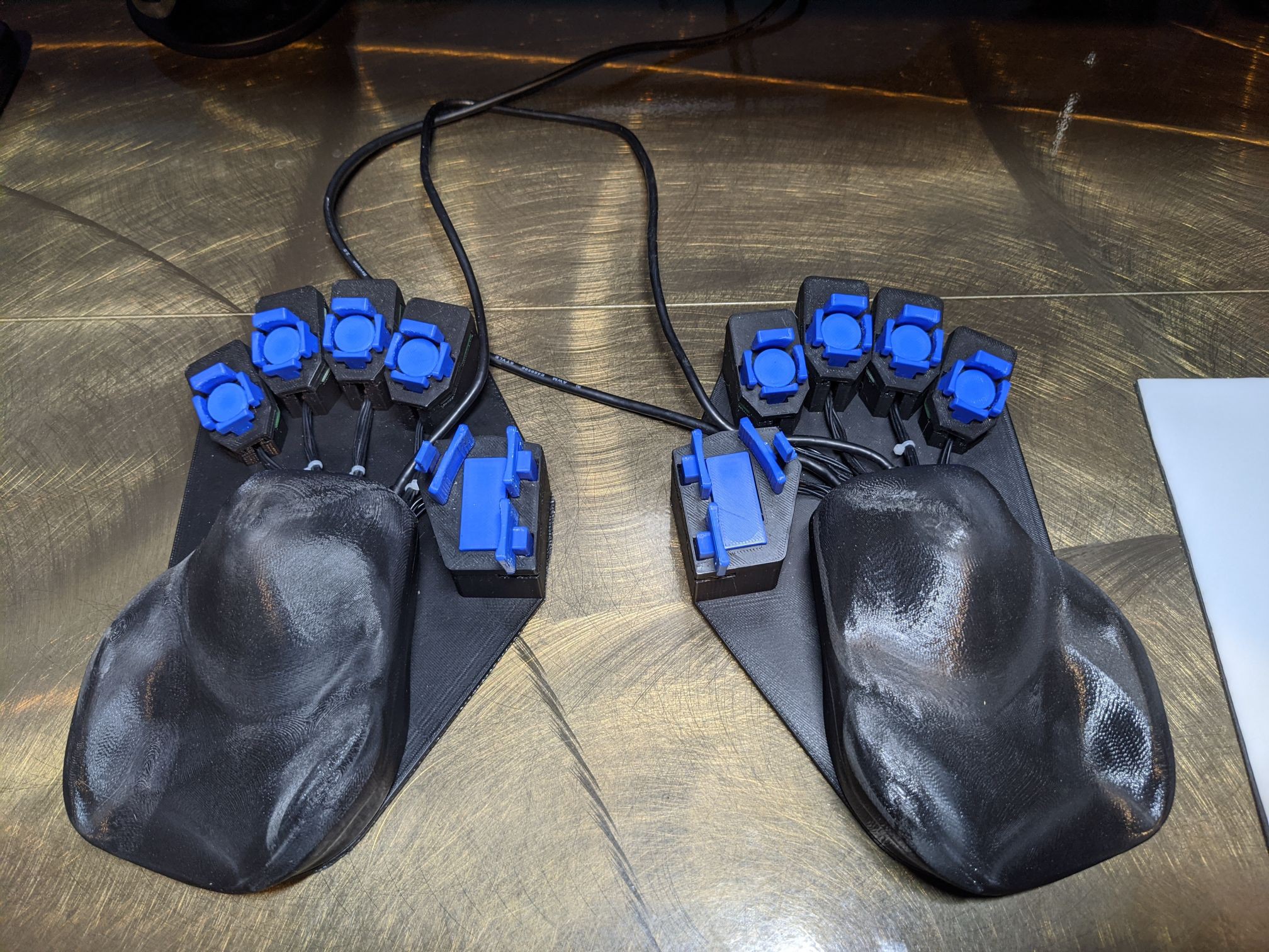
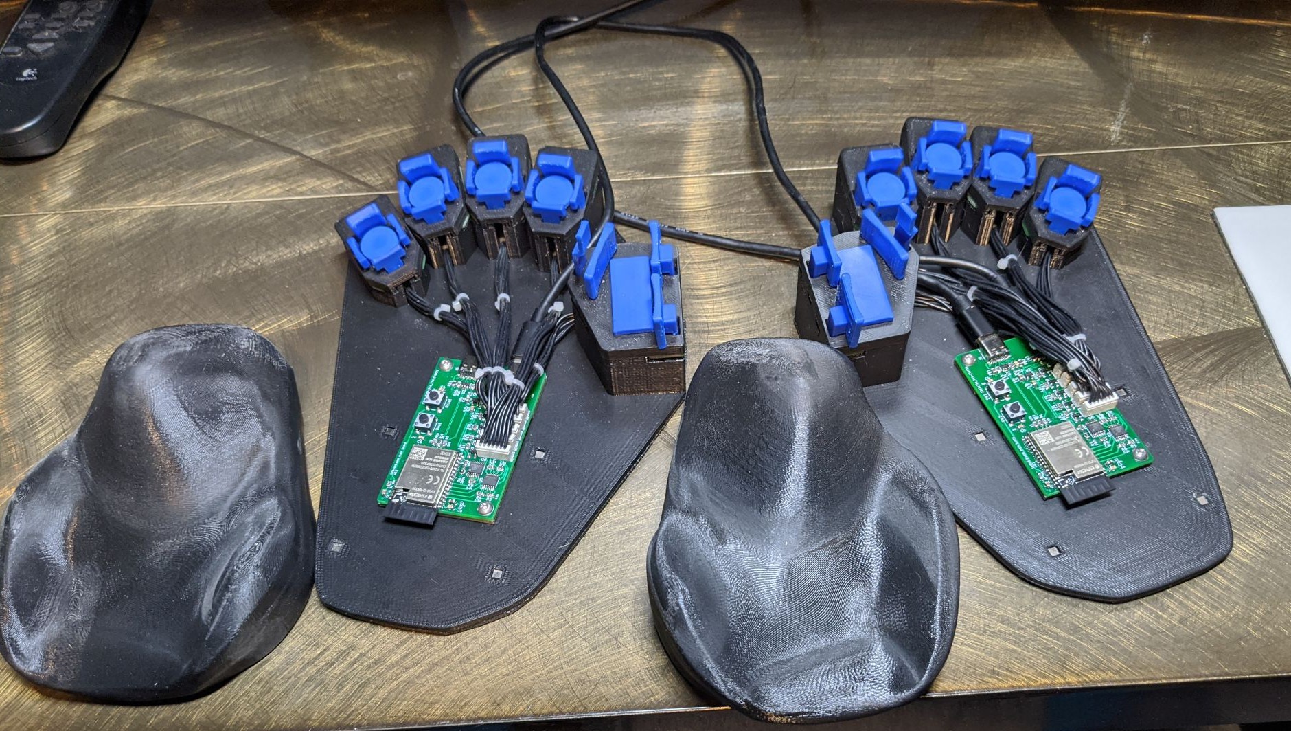
06/08/2021 at 08:34 • 0 commentsI've developed the designs for 2 different bases to attach the handrests and clusters to. One is based around a steel sheet, with the clusters attached magnetically, for maximum adjustability, and the other is a static design, with the clusters set at a specific location and orientation, for maximum stability.
Adjustable Design
![]()
![]()
Static Design
![]()
![]()
![]()
The idea is that you start out with the one that uses a steel sheet, and live with it for a while, adjusting the positions of the clusters until you're satisfied with how it feels. And then you take some measurements (exact method TBD) and use the position and orientation of all the clusters to make a static base.
When I was originally setting up my v1 lalboard, it took a while before I got everything positioned just right, with lots of small gradual tweaks as I tried to figure out the best positioning. It's surprising how much difference even moving a cluster less than 1mm can make in how everything feels under your hand.
The steel sheet is great for adjustability, providing six degrees of freedom/adjustability for each cluster. But it's not a great permanent solution, due to how difficult is it to get everything set up *just right*. So if you accidentally bump it and move things around, it's rather annoying trying to get everything back exactly where it was.
The static base solves this by providing a stable, immobile mount for the clusters. It's also smaller (no margin around the edges past the clusters), and provides somewhat better cable management (although I still have some ideas to improve this).
-
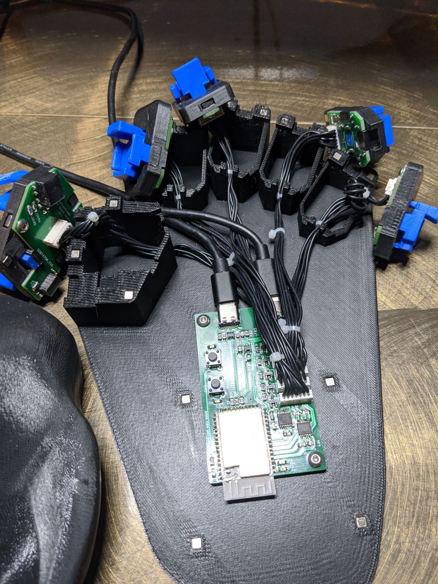
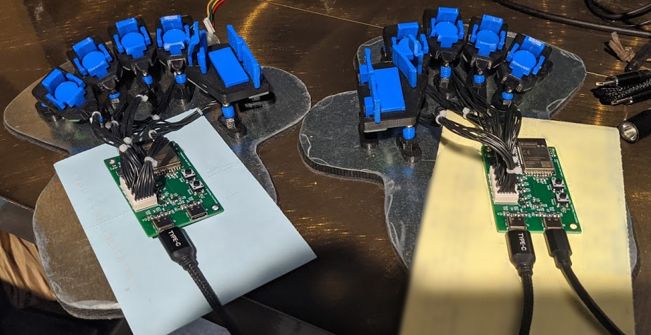
Central PCBs in, first full prototype up and working
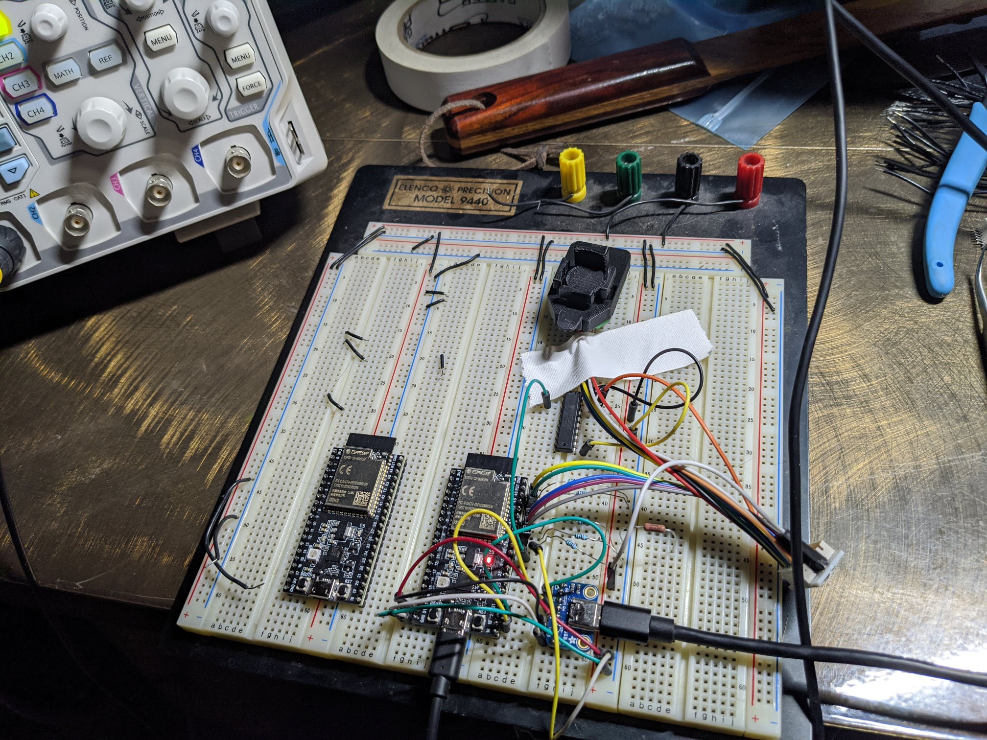
05/16/2021 at 23:10 • 1 commentThe central PCBs came in last week, and I got my first experience soldering fairly fine pitch SMD parts. I had just bought a stereo microscope recently, so I was able to put that to good use when soldering these.
The soldering wasn't actually nearly as hard as I was fearing. I think the USB-c connectors were probably the most difficult, but really not *too* bad. The ESP32-S2 module in particular was much easier than I was expecting.
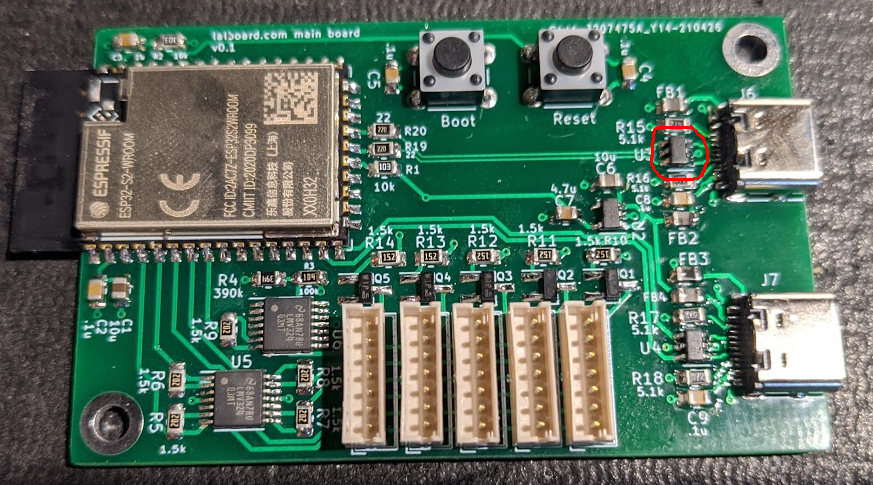
After I got the first board soldered up, I ran into a couple of snags. At first, it wasn't enumerating as a USB device when booting into DFU mode. I used a little usb-power meter I had and confirmed that it was drawing more power when booted normally than when booted in DFU mode, so I was fairly sure the ESP module was booting and running.
After a fair bit of poking around, and desoldering various parts, I finally realized I had soldered the little TVS diode for the USB-C port backwards. I fixed that and was finally able to get it enumerating as a USB device and then flash it.
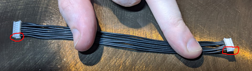
The next snag was that the clusters just weren't working. I wasn't getting any signal at all from the phototransistors. And again, after a fair bit of poking around, I finally realized I had wired the connectors backwards in the schematic and layout. At least, based on the way I had my existing JST-ZH cables wired. I had pin 1 on both sides as VCC, and pin 7 and ground. But of course, if the cable is wired normally, as mine are, the left pin (pin 1) on one side actually corresponds to the right pin (pin 7) on the other side.
Fortunately, this was an easy fix, since there was plenty of room on the board for the connectors to be placed the other way around. So I got those desoldered and flipped around, and was finally able to get the first keystrokes registered. Woo!
After that, there was a fair bit of futzing around with the firmware to get both sides working correctly and talking to one another. But I now have a working prototype, which I'm typing this log with :)
Now that I have a keyboard I can actually use, I've discovered a couple of minor problems that I'll need to address.
The first is that the central down keys have too much side-to-side wobble. You can feel them wobble as you place your fingers on them, and its a bit annoying. I did some quick tests, just placing some thin UHMW tape on either side of the post, and confirmed that that extra bit of thickness was enough to significantly reduce the amount of wobble. So I think I just need to tweak the size of the post and reprint them.
Another thing is that I noticed that I was commonly accidentally shifting the key after a shifted key press. I suspect the problem here might be that the thumb down key (the shift key) is registering as a press a bit too soon (and correspondingly, unpressing a bit too late). I want to see if I can figure out a way to measure the distance to when a press is registered, and compare the new design with the old design. I may need to tweak either the physical design of the thumb cluster a bit to compensate, or maybe just increase the drive current of the LED, so it requires the key be a bit further down before the phototransistor stops "seeing" enough light.
The other big thing that I'm working on is a better base. I'm thinking a plastic base (3d printed) with a void for a smaller steel sheet. The steel sheet will only be used for the clusters, but the handrest will be attached more firmly to the plastic base. I think this should have a few advantages over the current, somewhat ad-hoc, steel sheet solution.
- The handrest will be firmly attached and kept in position relative to the base plate. This allows the keyboard to be slid around by the handrest. With the handrests just attached magnetically to the steel sheet, if you try to slide the whole keyboard half by the handrest, the handrest just slides on the sheet, and becomes misaligned with the clusters.
- The steel sheet will be smaller, and will only have straight edges and convex corners, hopefully making it easier to manually cut out. e.g. by gluing a paper template to a sheet and using tin snips to cut it out.
- I'm thinking I can cover the edges of the steel sheet with an extra rim of plastic, making it look a bit neater, and avoiding having to clean up the cut edges of the sheet much.
-
Phototransistors, Transimpedance Amplifiers and Response Times, Oh My!
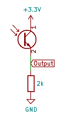
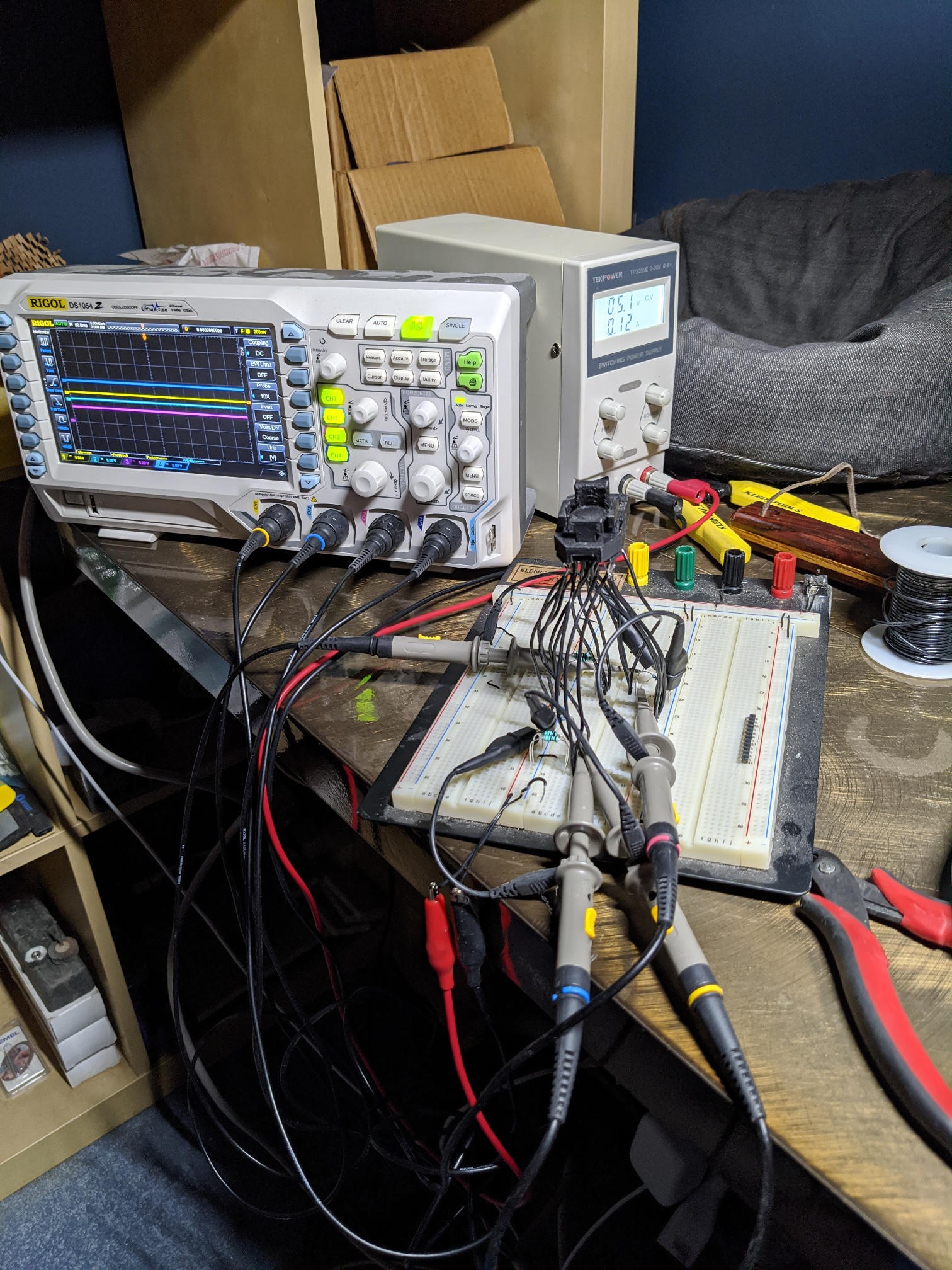
04/27/2021 at 05:59 • 2 commentsThe simplest way to use a phototransistor is to hook it up with the collector connected to a voltage supply, and the emitter connected to ground through a resistor. As more light hits the phototransistor, it conducts more current, and so the voltage across the resistor increases.
You can adjust the sensitivity of the circuit by adjusting the value of the resistor. Higher values provide higher sensitivity, but at the cost of slower response times.
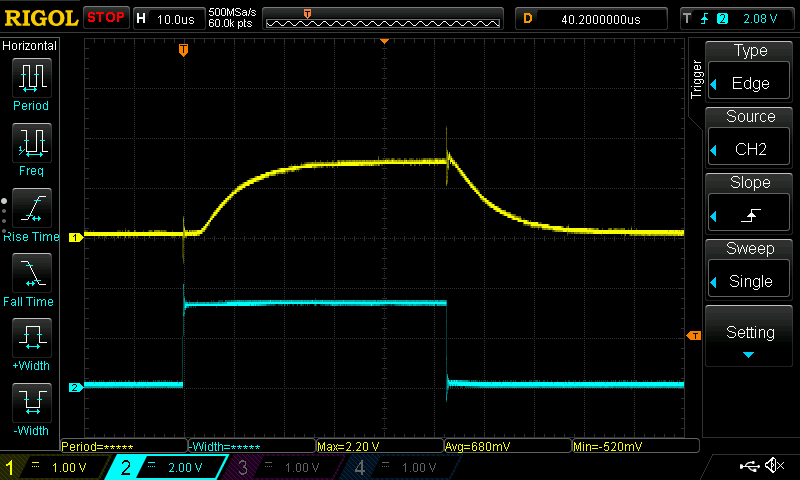
For example, here is the key activation waveform for a problematic switch I was investigating, which was using a 1k resistor.
Channel 2 (blue) is the selector for that that cluster, so a high value essentially enables/energizes the cluster, and a low value disables it. And channel 1 (yellow) shows the output voltage of the phototransistor when the key is in a pressed state, based on the above circuit.
As you can see, this particular switch is only reaching about 1.5V at its highest value, which is not high enough to register as a logical 1 value. And the rise and fall times are already a bit sluggish, at around 30us.
Swapping out the resistor for a lower value (470), we get the following:
The rise and fall times are much improved, but the sensitivity is even lower, and the max voltage doesn't even reach 1V.
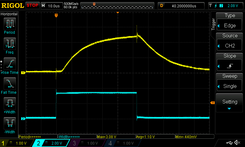
Going the other direction, here is what we get with a 2k resistor:
This is starting to look promising, with the max voltage reaching over 2V, which is the minimum required to register as a logical 1. However, the rise and fall times are now even worse, taking a full 50us before it starts leveling off.
I had a bit of trouble with this particular key in the previous design as well. The problem is that the key travel is very short, and the key stem doesn't entirely get out of the way of the light path, so less light is reaching the phototransistor. I solved this in the previous design by boosting the current/brightness of the LED for that switch, but even that wasn't enough to get a fast/high enough signal from the phototransistors in the new design.
The issue is likely the wider key stems in the new design. This increases the distance between the LED and phototransistor, and so even less light is reaching the phototransistor, and it's just not able to get enough light.
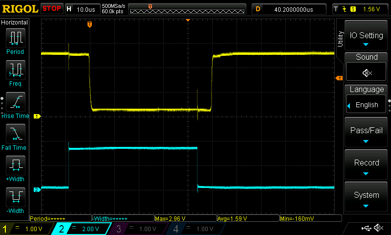
And this is where the transimpedance amplifier (TIA) comes in. It's a fancy name for a particular arrangement of an opamp, such that it converts a current-based signal (like that from a phototransistor) to a voltage-based signal (like what is needed on a gpio pin). The main benefit in this application is that it has a very low input impedance. And similarly to when we swapped out the resistor in the first circuit for a lower one, a lower input impedance means that the phototransistor is able to respond more quickly. And, critically, the input impedance is independent of the sensitivity/amplification factor.
In this circuit, the 2k resistor serves a similar purpose as the resistor in the first circuit. A higher resistor value increases the amplication and results in a higher output voltage. But without affecting the rise and fall times of the phototransistor, because the phototransistor still "sees" the opamp's low input impedance.
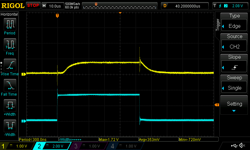
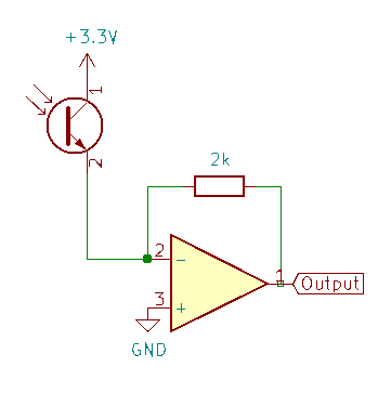
And here's the key activation waveform after switching to a TIA.
One thing to note is that the TIA inverts its output. So instead of a low-to-high transition when a key is pressed, it is now a high-to-low transition. And both the high and low voltage levels are at comfortable logic levels.
As you can see, the response time is much quicker now, with the voltage leveling out after only ~10uS after the cluster is enabled.
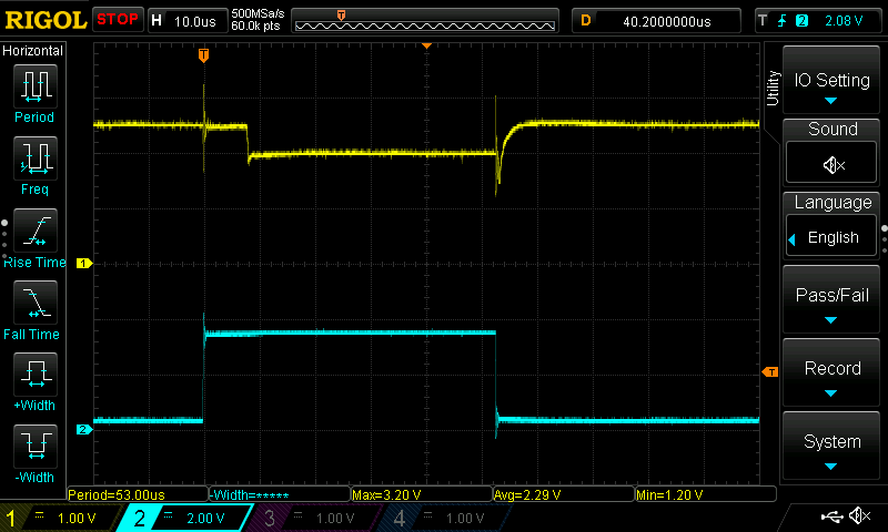
The above was with a 2k feedback resistor in the TIA circuit. Just for comparison, with a 470 ohm resistor instead, we get:
The sensitivity is lower as expected, with the low voltage level only being about .5V below the high voltage level. But the response time is largely unaffected.
Using TIAs for the new design has a few advantages
- It's able to deal with that pesky thumb switch that doesn't get much light
- It minimizes the response times of the phototransistors, which allows for shorter duty cycles (and thus less power usage) when scanning through the matrix.
- It boosts the sensitivity of the phototransistors, so the LEDs can be driven at much lower current/brightness. The original design drove them at around 25mA each, with 5 LEDs lit at a time per side, for a total current draw of 250mA. But with the increased sensitivity, I can drop the current down to around 5-10mA each*, for a total draw of only ~50-100mA.
(* except for the problematic switches on the thumb clusters)
-
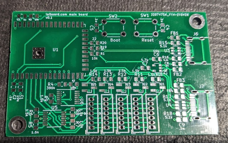
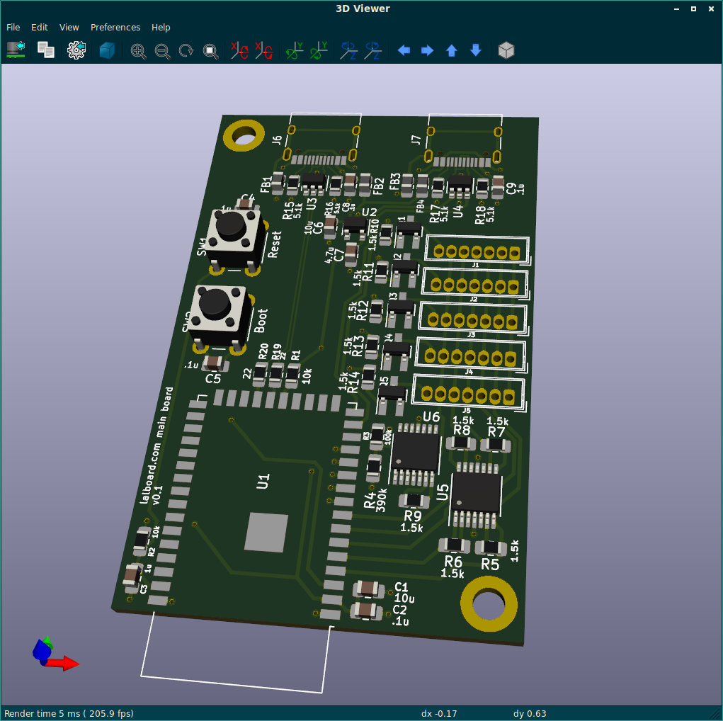
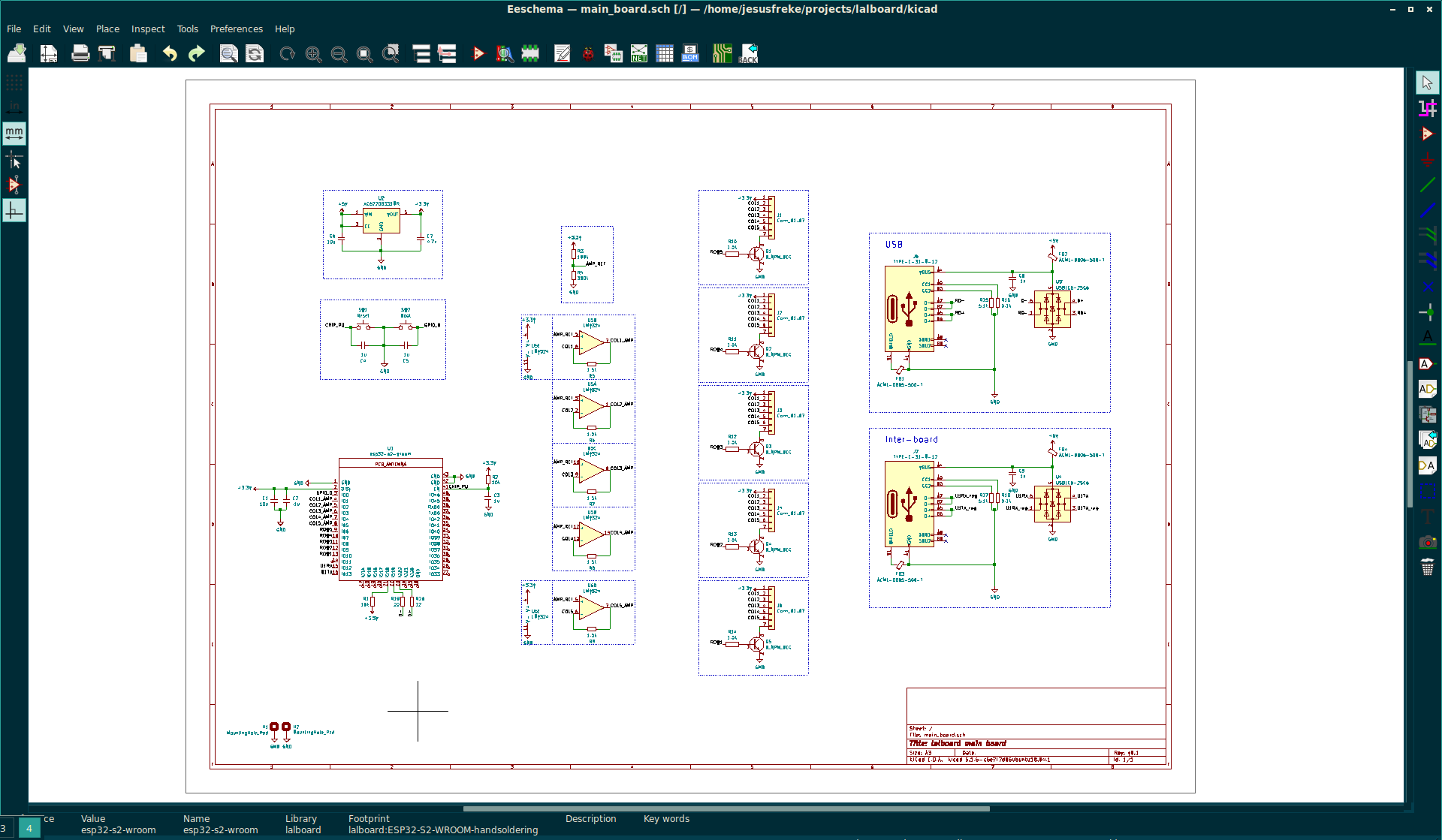
main board sent for fabbing
04/26/2021 at 20:13 • 0 commentsI've been spending some time designing and prototyping the new main board. There are a number of improvements compared with the v1 board (in addition to just being an actual PCB, rather than the ad-hoc thing using the vinyl cut process).
At first, I was thinking I would use an esp32s2 dev board, like the saola board, and just have a header socket for it on the main board. But I eventually came to the decision that it would be better to go a bit "lower level" and design a board around the raw esp32s2-wroom module.
For one thing, the saola dev board is fairly large, and would be hard to fit along with everything else needed in the space under the handrest. But it also uses a serial<->usb converter chip, instead of exposing the actual usb interface. You can still wire up a separate usb port to the gpio 18 and 19 pins, but that's a lot of wasted board space on an unneeded usb connector and serial conversion chip.
A few of the features/improvements:
- USB C port (because USB C >>> USB micro)
- It has a second USB C port for communication between the two halves. Although this isn't a real USB port. The actual communication will be a serial link over the D+ and D- pins. I didn't particularly like using a USB port for non-USB communication, but the best alternative I could come up with was a TRRS jack -- which isn't really hot-pluggable (e.g. shorting pins when you insert/remove a plug). So supporting hot-plugging won out over my concerns about confusion over the 2 different usb-c ports on each half.
- It uses discrete transistors to select each individual cluster (row) when scanning the matrix. Previously, it used an LED driver chip, but it was a bit of an expensive, specialty chip. Using discrete NPN transistors is cheaper, and they're much more ubiquitous.
One of the more significant changes is that it now uses transimpedance amplifiers to read the signals from the phototransitors, which you can read more about in my previous post.
I honestly didn't want to go that route initially, because it adds yet more components and complexity, and required embiggening the board. But I just wasn't happy with the phototransistor response times.
I do think it was the correct decision though, and it should help ensure more reliable operation of the optical switches, and enable even lower power usage due to lower LED currents and shorter duty cycles. Power usage isn't necessarily a huge concern atm, with a usb-powered device... But since it's using a bluetooth-capable chip, I won't rule out a battery powered bluetooth device in the future :)
-
First PCBs received, and first keypresses registered
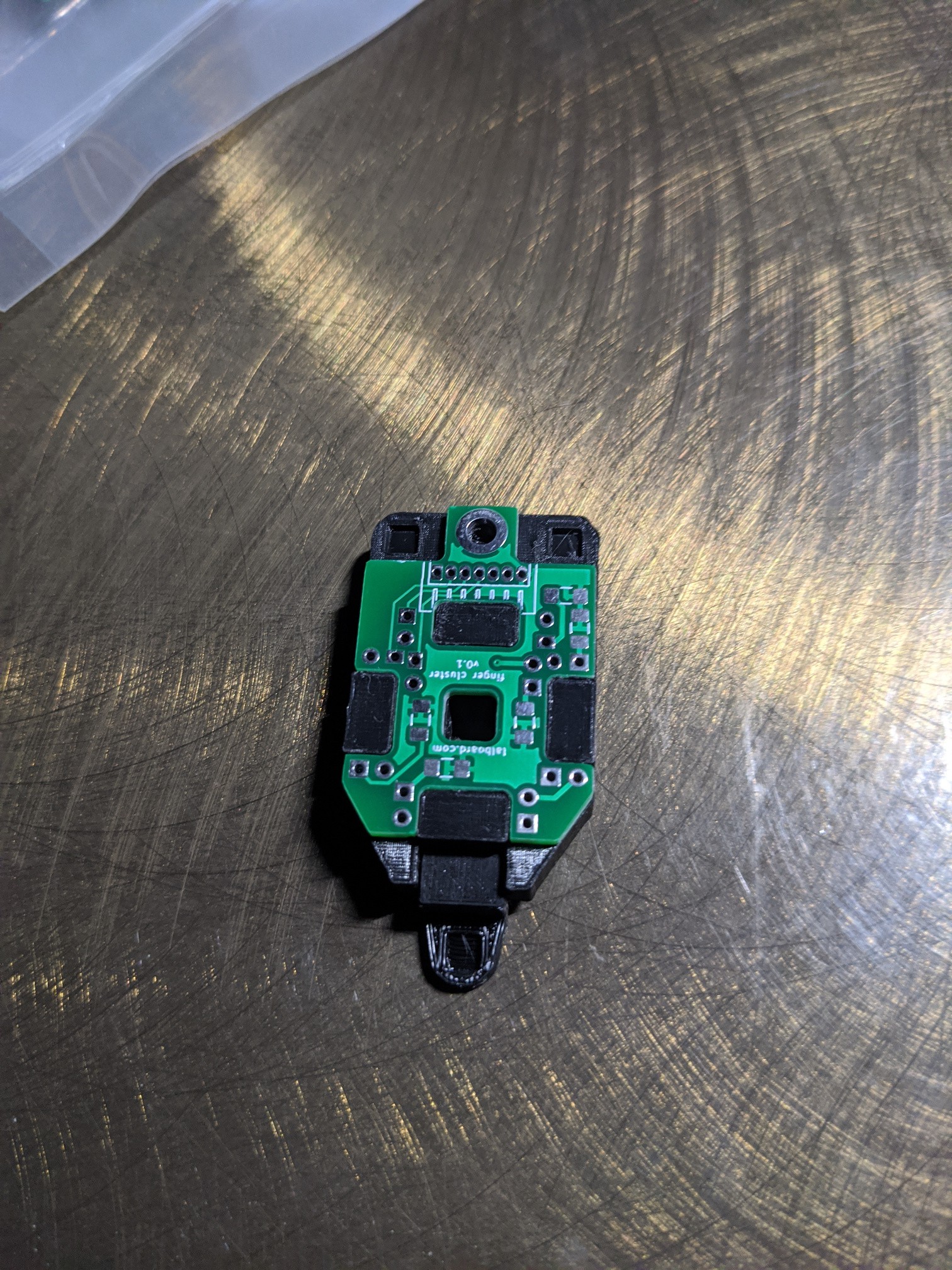
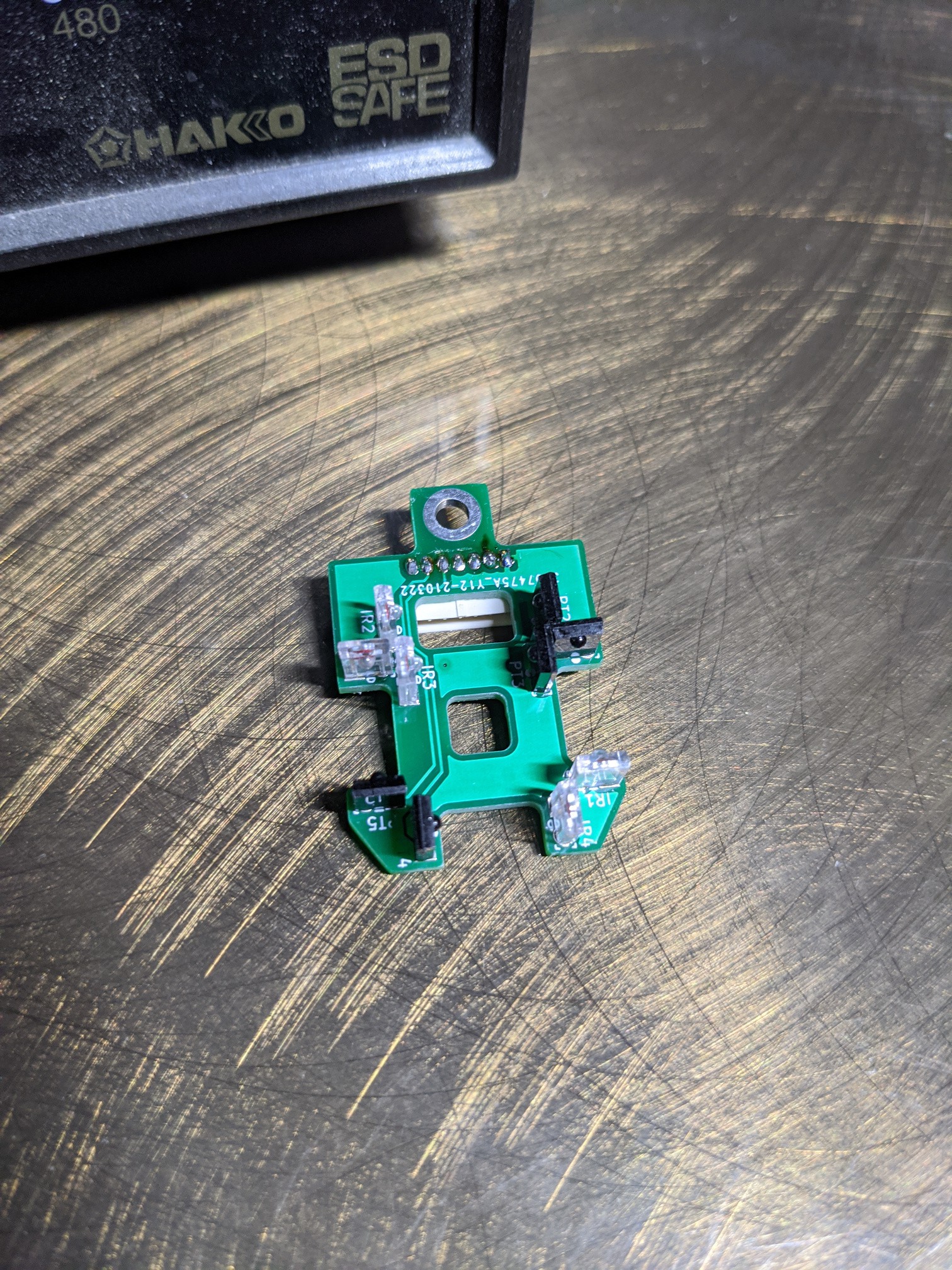
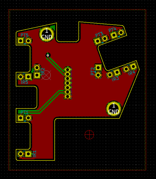
04/08/2021 at 09:05 • 2 commentsI got my order of PCBs for the finger and thumb clusters in from jlcpcb today. Exciting! My first time designing and having a PCB made. I'm super happy with the result. Surprisingly, everything seems fine with them so far.
![]()
![]()
I got one soldered up and attached to a cluster, and was able to send my first key presses with it, with the current in-progress QMK firmware.
![]()
![]()
-
First QMK keypress on esp32s2
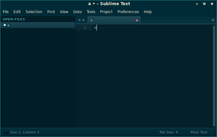
04/01/2021 at 06:58 • 0 commentsI finally managed to hook everything up so that qmk, tinyusb and esp-idf all play nicely together, and managed to get that first glorious "a" key press, from the on-board button on the saola board.
There's still a lot of functionality that doesn't work yet, but I'm super happy that all the USB stuff is working well enough that it's able to enumerate and actually send an HID report on a button press.
-
Initial testing of new cluster design
03/28/2021 at 10:38 • 0 commentsI finally got in some parts I had been waiting for from digikey, and was able to throw together a little hand-wired prototype using the new cluster design. I was able to verify there's no light leakage problems between the different keys, and all keys were causing a high enough voltage swing on the phototransistor to trigger a high logic level.
I also realized I had been carrying over the assumption from the previous design that everything would be driven at 5V. But the ESP32's input pins aren't 5V tolerant, so I'll need to switch everything to 3.3V. So I swapped out the LED resistors for a lower value to maintain the same current, and verified again that there's enough of a voltage swing at 3.3V for all the keys.
![]()
Incidentally, all those 22g solid copper wires don't make a half-bad mount for the cluster. It's not quite stiff enough, but maybe if the wires were shorter or a bigger gauge. That might be an idea to explore in the future, for a different type of adjustable mount.
-
Investigating QMK on the esp32
03/24/2021 at 07:29 • 3 commentsQMK seems to be a popular open source keyboard firmware. I've read through their docs a bit, and I think it should mostly support everything that is needed for the lalboard. Namely split keyboards and a robust key mapping mechanism that should be able to support the various mode keys/modes that the lalboard needs.
The only problem is that it doesn't support esp32. I guess I *could* switch to a compatible board/MCU, but a brief search doesn't show anything readily available that is as featureful, available, and cheap as esp32. And there seems to be at least some demand out there for running qmk on an esp32, so I thought I would poke at it bit.
After much gnashing of teeth (and keys), I managed to get a very very hacky proof of concept that compiles and links. This involves
- adding a new esp32 platform to qmk (currently mostly just stubbed out)
- tweaking qmk's build system to build a static library, instead of a full firmware image
- creating a new esp-idf project, that calls into qmk to perform the various processing tasks needed in the main loop. (i.e. something similar to the main loop for the LUFA protocol)
- manually copying that qmk static library to the esp-idf project, and ensuring it gets linked
This is far from an actually functional proof-of-concept, but I think I'm convinced it's at least within the realm of possibility now. I think the next steps will be to more fully implement and integrate the new esp32 functionality in qmk, and ideally figure out some way to link the two builds, to avoid having to build in multiple places and copy stuff around between them.
I doubt something like this would be accepted by the qmk maintainers, since it's essentially using bailing wire and duct tape to smoosh 2 different build systems together. But hopefully it can at least serve as a template for others who want to use qmk on an esp32.
-
Thumb clusters/pcbs mostly done
03/22/2021 at 19:58 • 0 commentsI think I've pretty much finished updating the thumb clusters. I added an .stl and .f3d assembly export for both thumbs, along with an online viewer thingy (links: left, right). And the kicad designs for the PCBs have been updated.
I'm currently waiting on a digikey order for the optical components, to be able to verify the optical performance of the finger and thumb clusters. That order also has some Saola ESP32-S2 boards that I want to play around with, and see if it might be feasible to port the QMK firmware to.
I'm holding off on starting work on the central PCB for now, since that will depend a fair bit on what dev board I end up going with to drive it.
-
cluster assembly now viewable online
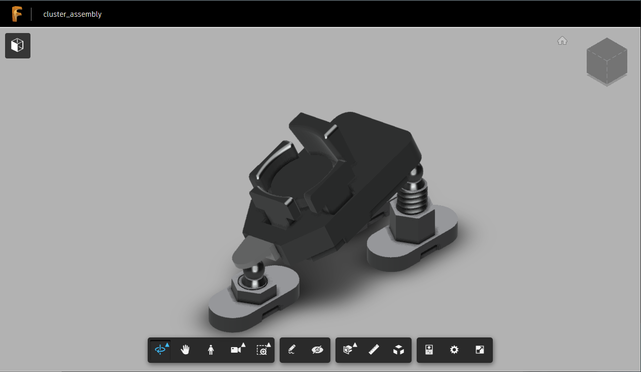
03/18/2021 at 05:37 • 0 commentsI finally got around to creating a full assembly for a single finger cluster, with all
the various parts in their correct places. The "stls" folder in the github repo should now contain an .stl and an .f3d (fusion archive) for the cluster_assembly part.
I also threw it up on the fusion cloud, where I think it can be viewed by anyone, without logging in. You can check it out here.
lalboard - Ergonomic Keyboard
A 3D-printed keyboard inspired by the DataHand.