 Capt. Flatus O'Flaherty ☠
-
1Overview of the 'Renegade LT100E' quad bike
![]()
On delivery of the quad bike, we took off all the plastic panels, inserted the main fuse and tested the motor with the bike up on wooden blocks. Video 1 shows the main features and build quality of the bike and we also hacked into the throttle connector with a 5v arduino uno to test what the signal to the motor controller should look like. The signal was the 'analog out' type, which is a high frequency PWM that 'attempt' to replicate a true voltage out. We successfully ramped the motor steadily up and down. NB. The green wire on the throttle connector is for the signal.
Here's the code to ramp up the motor:
void setup() { pinMode(11, OUTPUT); pinMode(13, OUTPUT); // Serial.begin(9600); } void loop() { for (int speed = 0; speed < 155; speed++) { analogWrite(11, speed); delay(20); // Serial.println(speed); digitalWrite(13,HIGH); } for (int speed = 155; speed >= 0; speed--) { analogWrite(11, speed); delay(20); // Serial.println(speed); digitalWrite(13,LOW); } // pause between LEDs: delay(100); } -
2Steering actuation
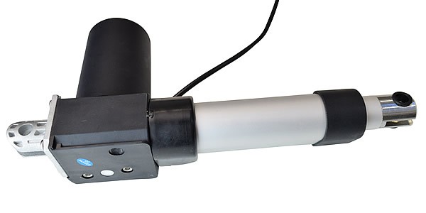
The installation of the steering actuator is shown below, it's a thumping great 4000 N device capable of tearing the whole machine apart if not careful. The actuator needs to be able to turn slightly at each end and so is mounted on the stainless steel brackets to enable this. Also, the actuator must operate at exactly 90 degrees to the steering column or else there will be unwanted twist in the actuator as it move in and out that could damage the mounts at the ends. The actuator requires a high ampage, 12 volt supply and can be control via mechanical relays or MOSFETs. MOSFETS are much more expensive but more reliable and can be controlled directly from a micro-processor such as an Arduino, whilst the relays require an intermediator y chip, the L293E, to boost the power supply for the coils.
![]()
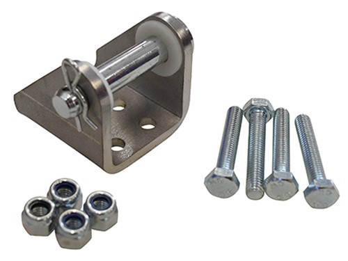
This little beast is the Gimson Robotics GLA4000-S 12V DC Linear Actuator. It boasts a massive 4000 N of force, which is enough to pull the whole robot to pieces ! The actuator requires 2 stainless brackets for attaching to the robot frame:
![]()
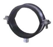
Some heavy duty 3/8" pipe clips were used to attach to the frame:
![]()
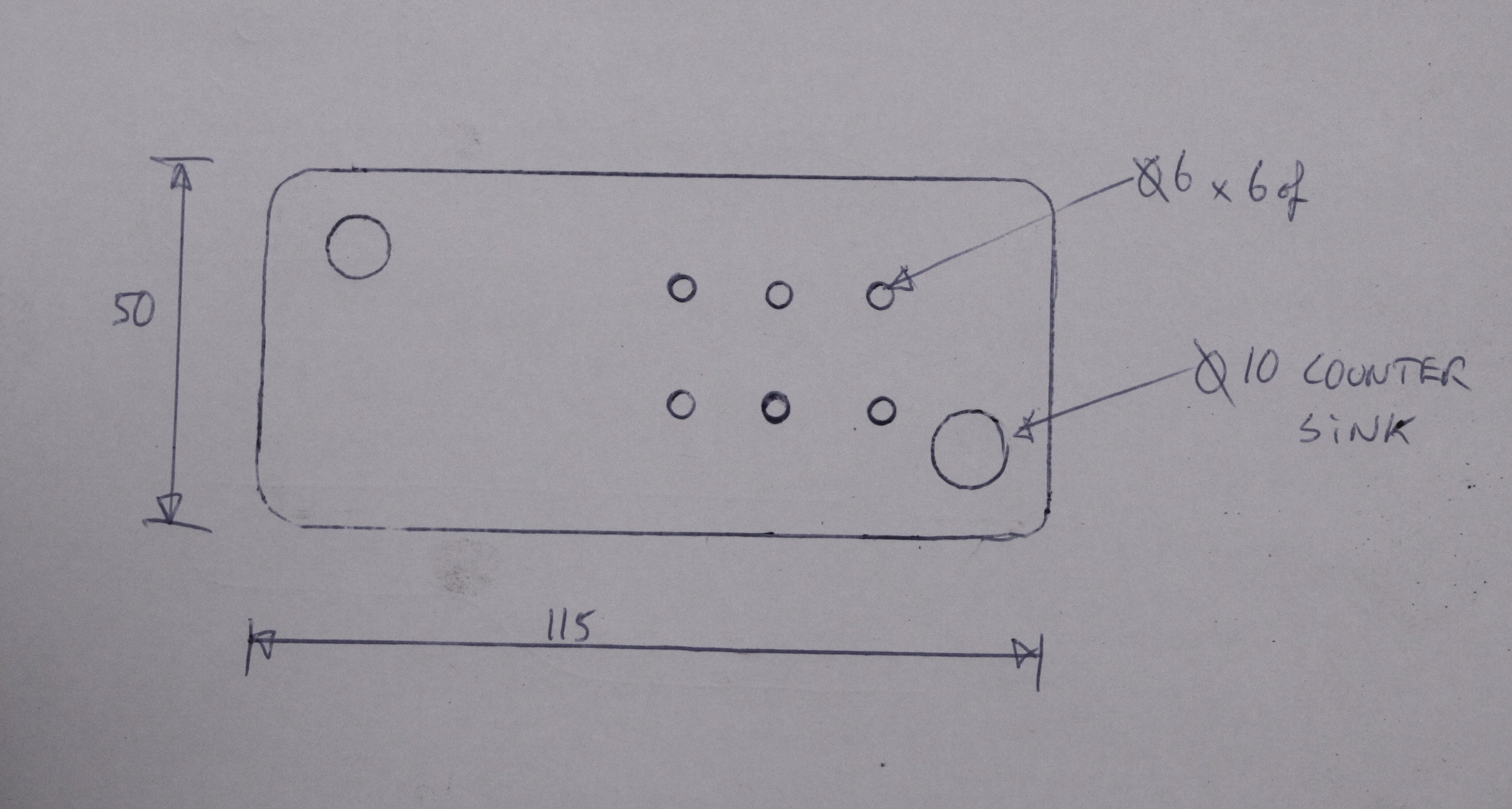
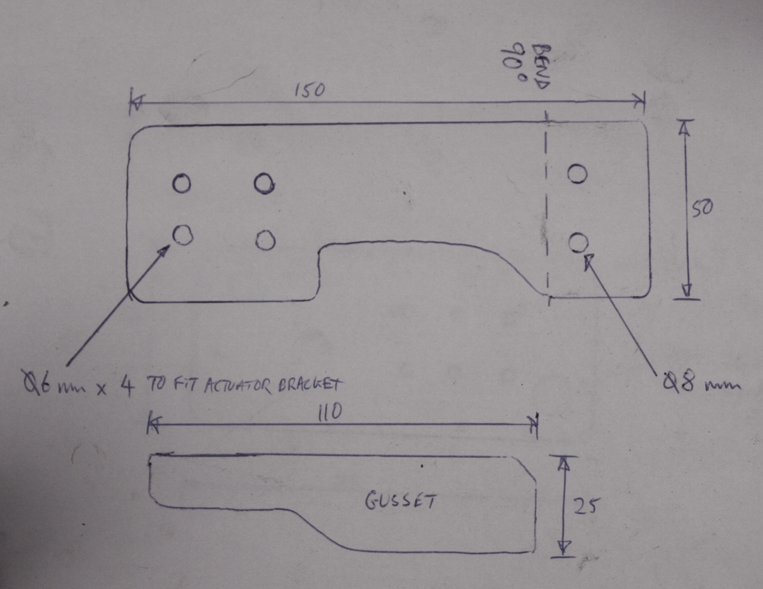
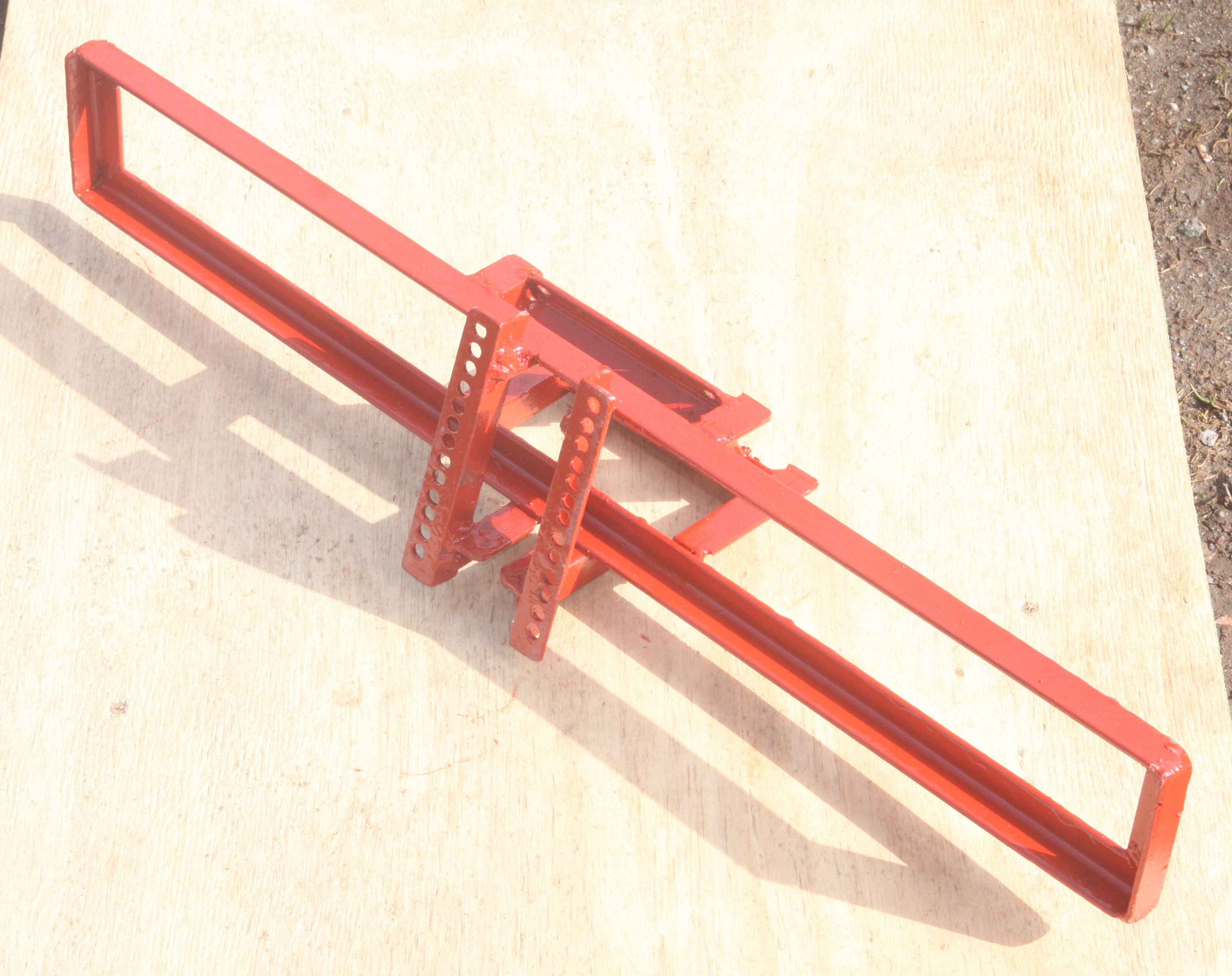
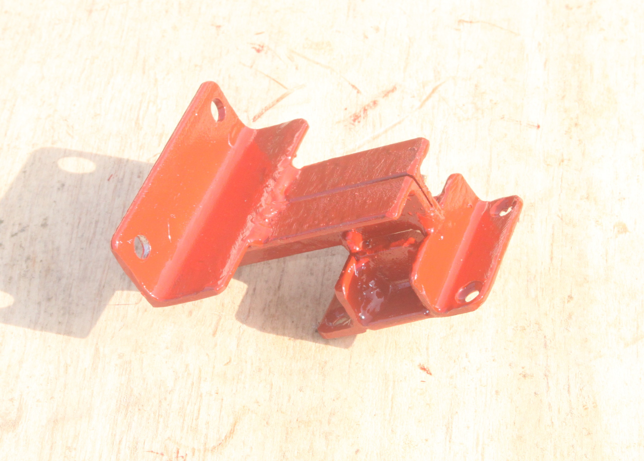
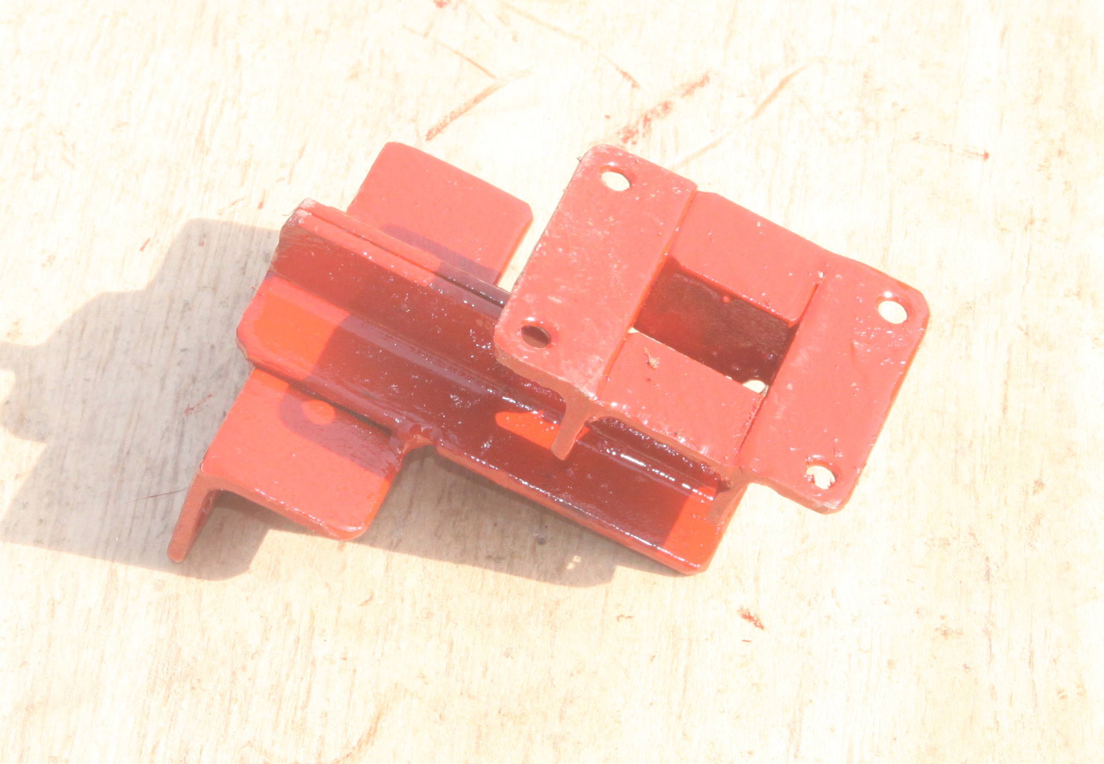
We made some custom mild steel brackets to mount the actuator:
![]()
![]()
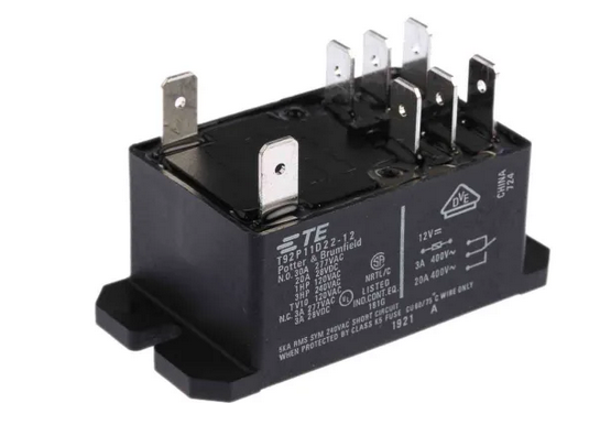
..... and used some 30 amp relays to handle the high current ( TE Connectivity, 12V dc Coil Non-Latching Relay DPDT, 30A Switching Current Flange Mount, 2 Pole) :
![]()
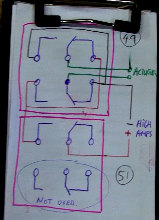
Circuit diagram for the relays:
![]()
-
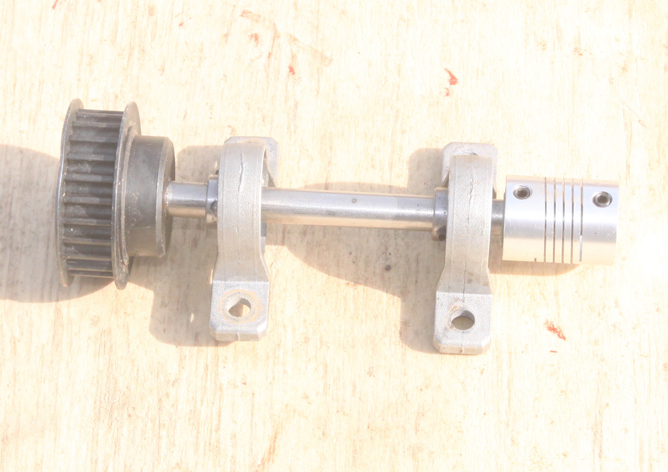
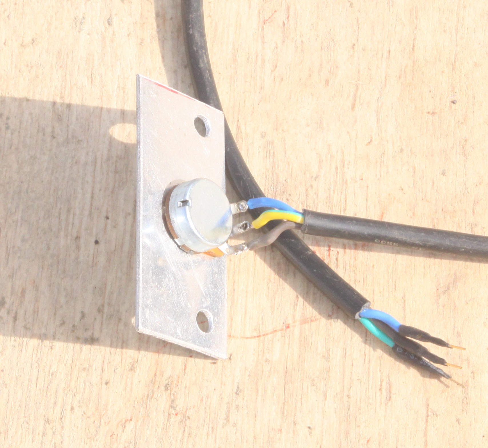
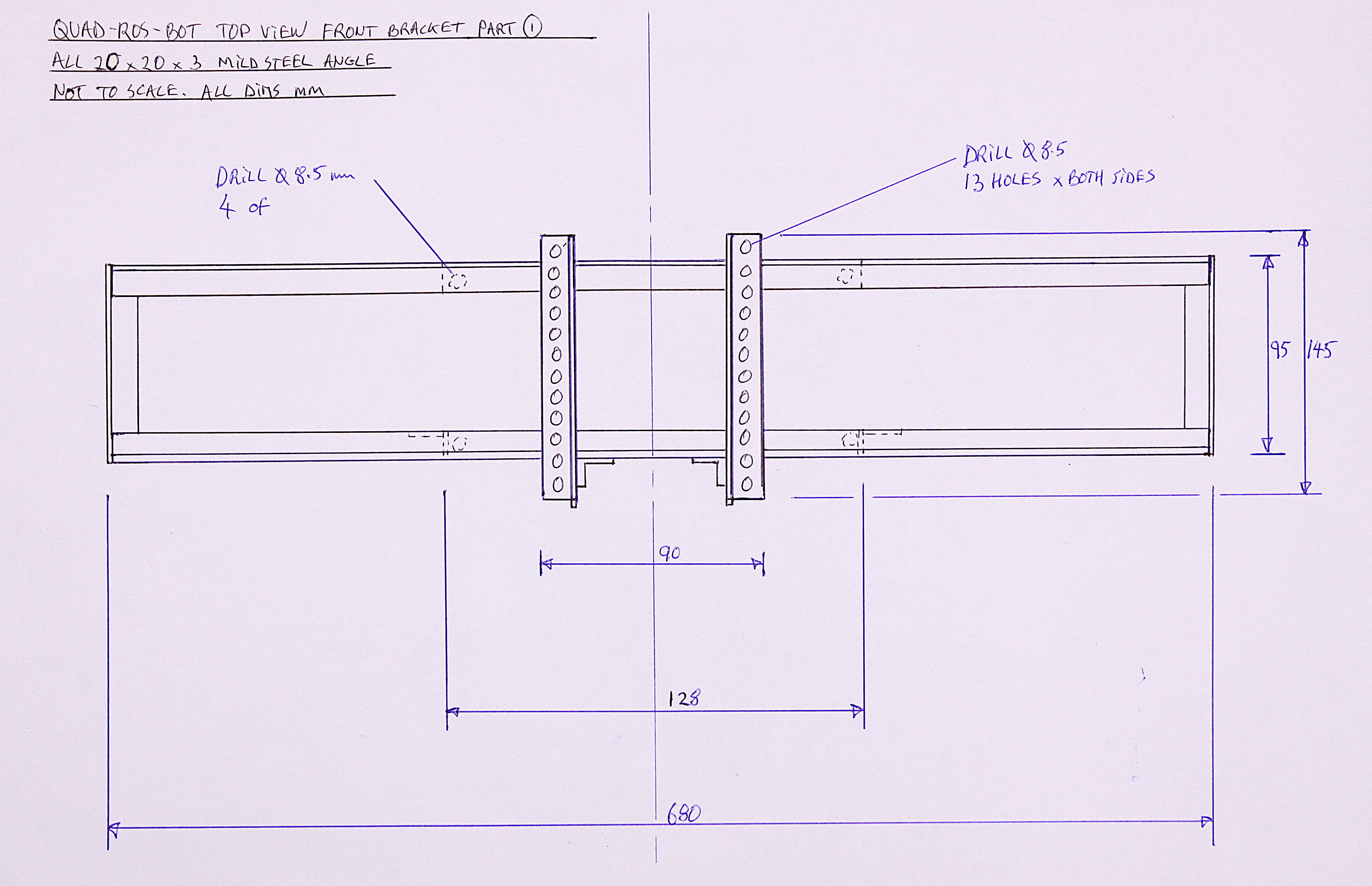
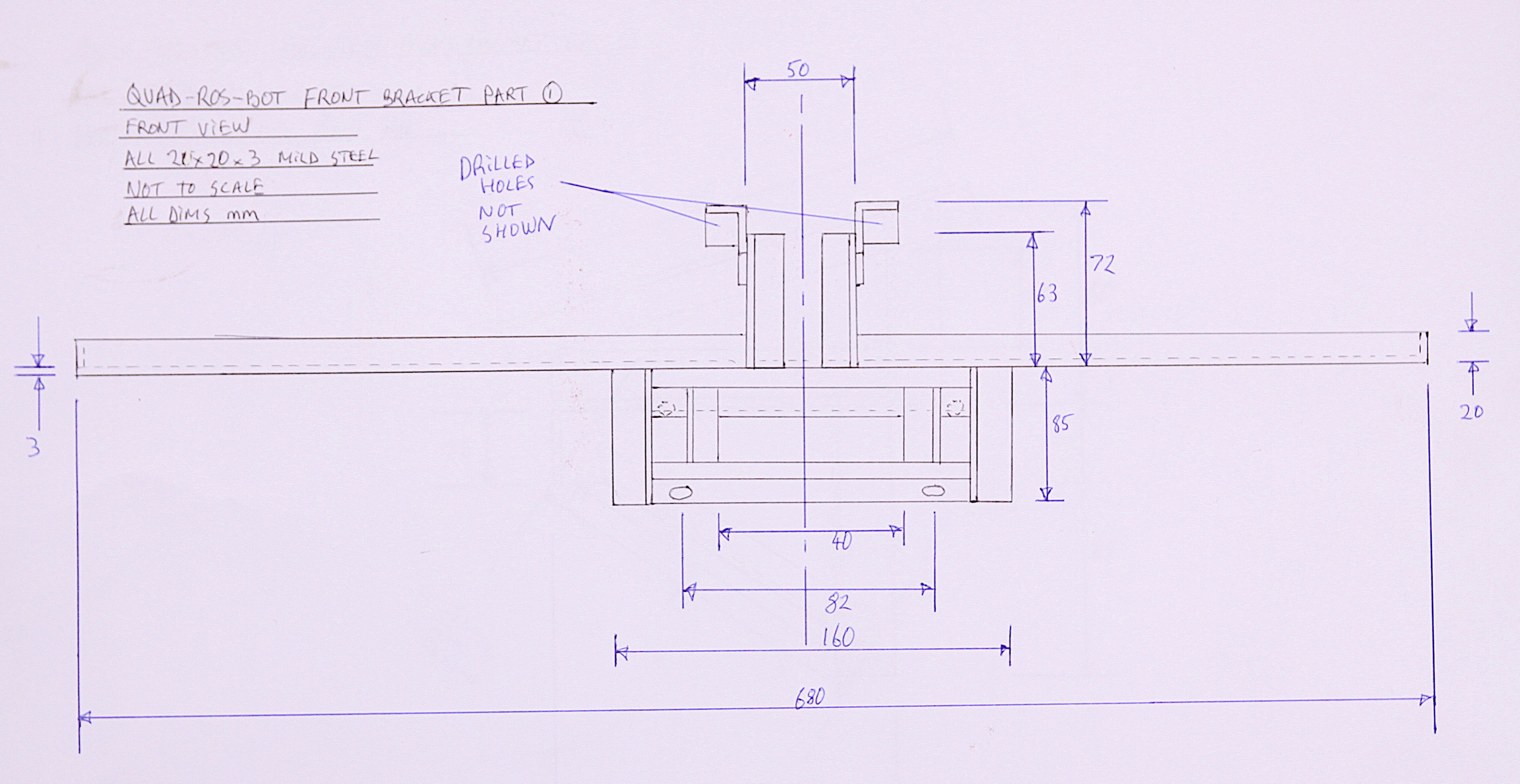
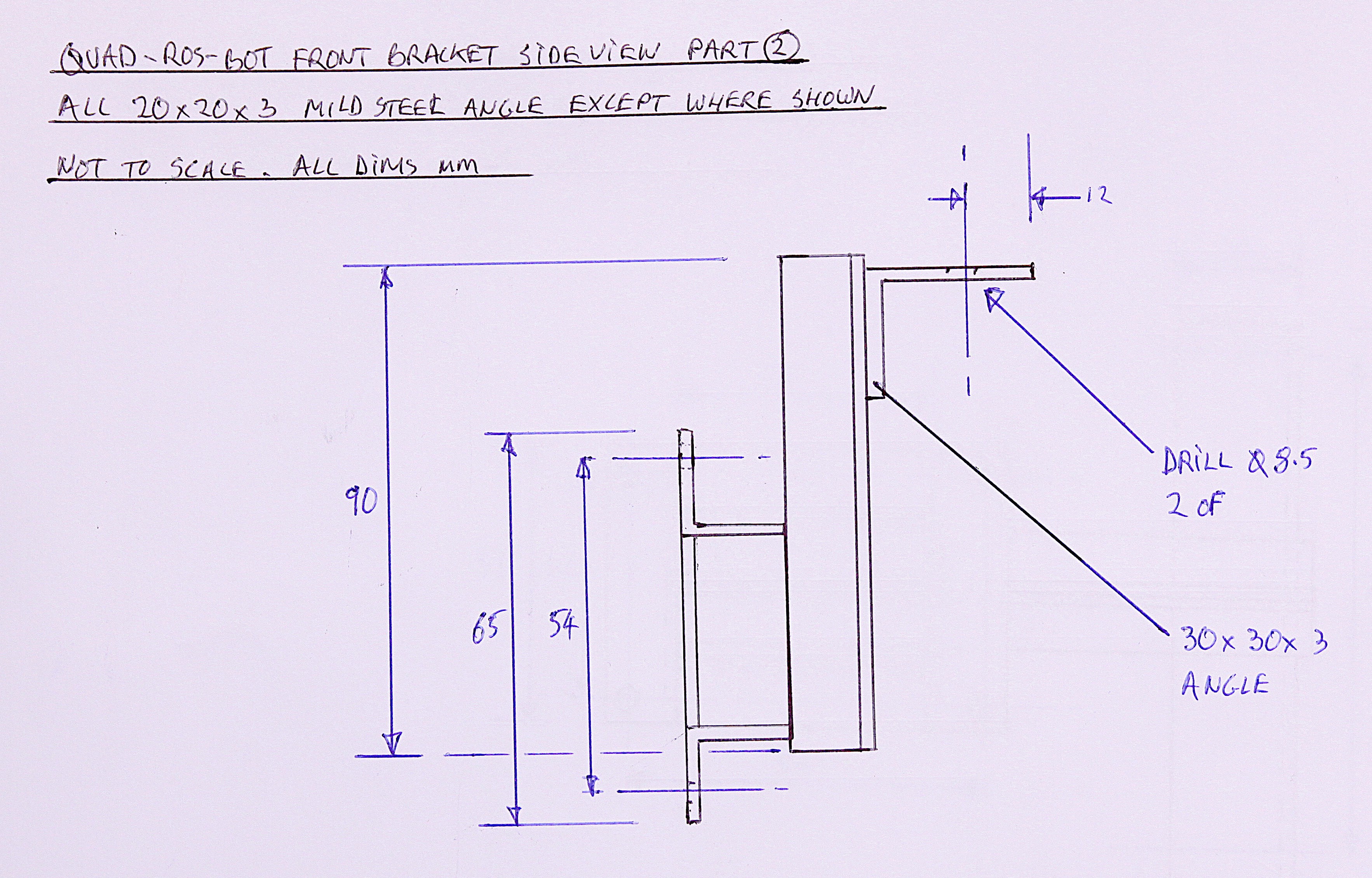
3Front sub frame and steering position sensor mount
![]()
This strange looking frame goes at the very front of the robot and performs two important functions. One is to mount a load of the sensors and antennae for the control system, and the other to mount an everyday 10K potentiometer to measure the steering angle. The steering angle is NOT measured by bolting the pot directly onto the top of the steering column , but via a gearing reduction timing belt to make better use of the pot's range and hence better resolution. This also has the benefit of hiding the pot deep within the frame work, well out of harms way. Video 3:All the photos and drawings needed to build the sub frame and bracket are given in this step, below. The important thing is to present the potentiometer assembly exactly parallel to the steering column or else the whole thing will fail and the belt might also come off the timing cogs. To prevent play, or backlash, the belt needs to be fairly tight, so the welding needs to be strong. The belt also needs some adjustment and this is enabled by the series of parallel holes drilled in the angle as seen in the photo above. Slots would also be a good option if a milling machine is available.
The pot range and resolution was tested by using the Arduino Uno code below and we managed to get 340 units across the whole steering range, which is thought to be more than adequate. This could be further improved by using a gear ratio of 1:4 instead of 1:2.
![]()
![]()
![]()
![]()
![]()
![]()
![]()
![]()
![]()
Code for testing the potentiometer:
int sensorPin = A0; int ledPin = 13; int sensorValue = 0; void setup() { Serial.begin(9600); pinMode(ledPin, OUTPUT); } void loop() { sensorValue = analogRead(sensorPin); Serial.print("Pot value (0 to 1024): "); Serial.println(sensorValue); digitalWrite(ledPin, HIGH); delay(250); digitalWrite(ledPin, LOW); delay(250); } -
4Motor Upgrade
We decided that the standard motor on the QuadROSbot was not suitable for travelling over rough ground at slow speed - it was more suited to speed rather than torque. The motor chosen for the upgrade was a 3 phase 48 V DC motor with a 5:1 planetary gearbox that could be slotted into the robot without too much modification of the rear suspension sub frame. It's always a big risk buying motors from China and when it arrived the aluminum mountings were bent out of shape like it had fallen off a conveyor belt somewhere.
![]()
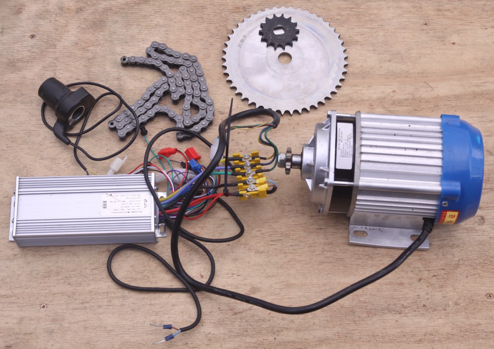
Fortunately, all went well as the mountings just bent back into shape once it was bolted onto the steel subframe. Other parts required were a 3 phase sine wave controller and some gear sprockets:
![]()
The sprocket sizes were dictated by the absolute minimum size that could be mounted on the motor, which turned out to be 8 teeth in size and the maximum on the wheel shaft without causing ground clearance problems, 48 teeth. The chain is a standard 1/2" pitch. The large sprocket was taken to a machine shop to have the center hole widened slightly and the small sprocket was ground and filed by hand to get it to fit the motor shaft.
The QuadROSbot wheels were removed to expose the drive shaft:
![]()
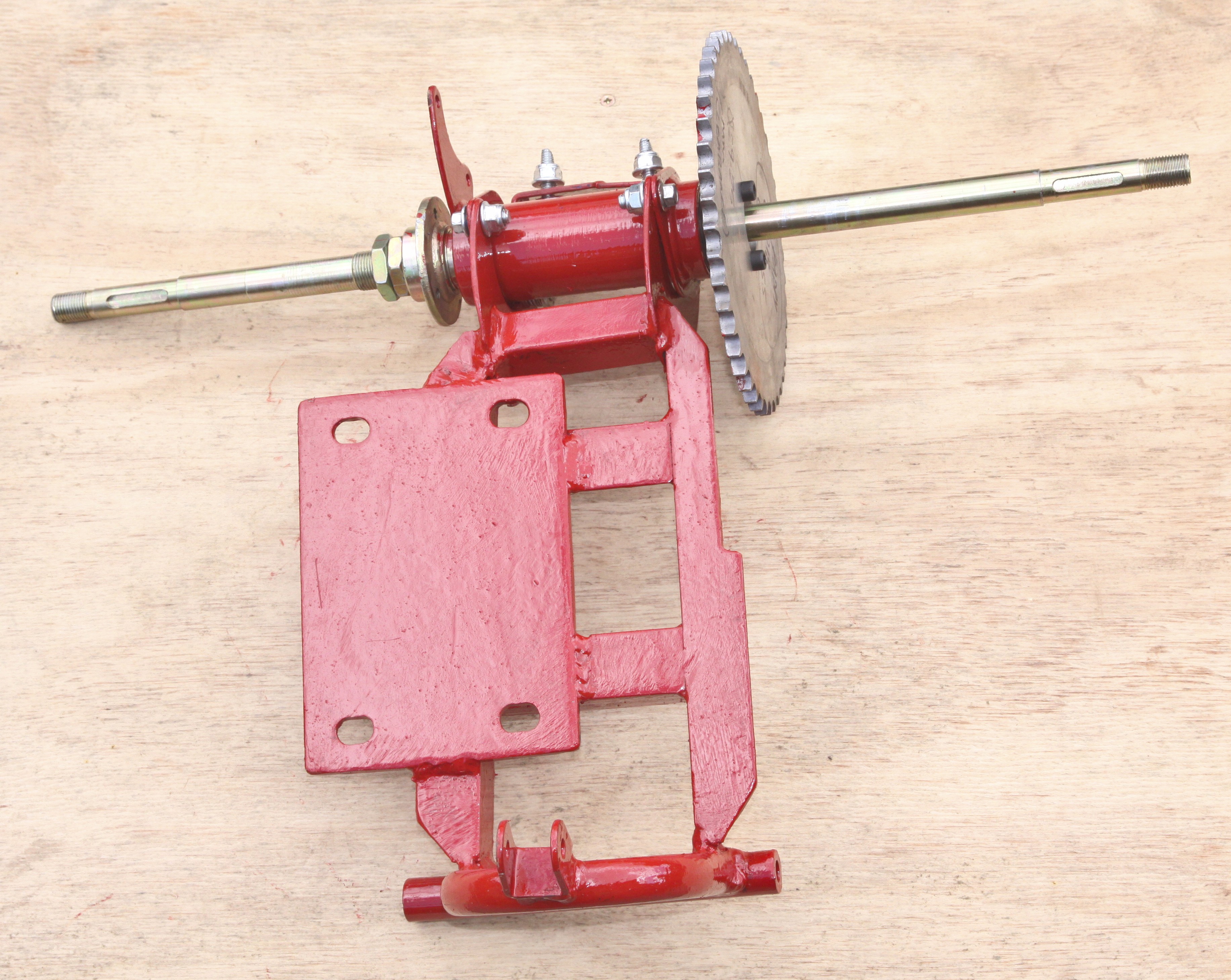
The rear suspension subframe was then removed:
![]()
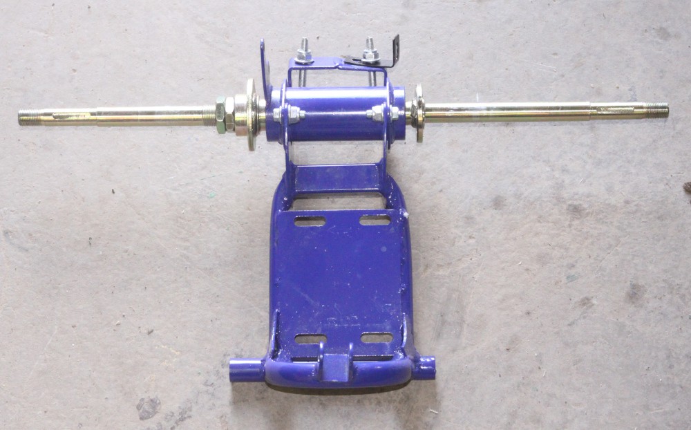
This subframe was then completely rebuilt, recycling the top and bottom bearing systems:
![]()
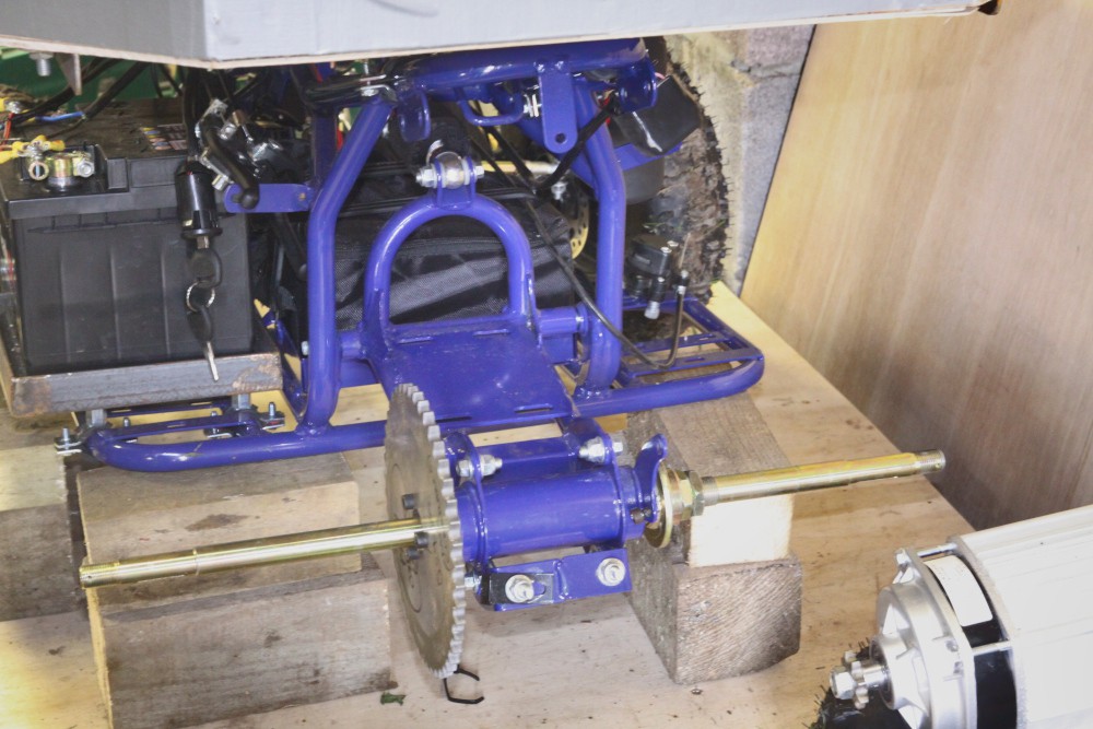
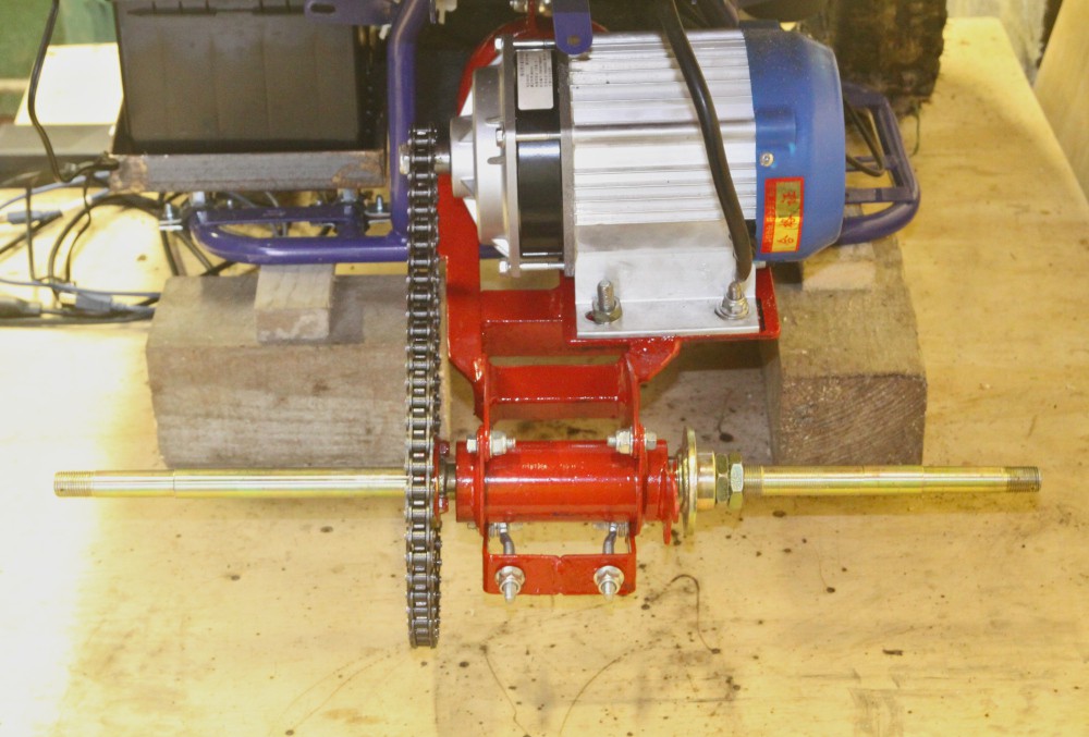
Then slotted back into the main frame with the new motor. Since the mountings are slotted, there is plenty of opportunity to adjust the motor position so that it is perfectly aligned with the main sprocket. This was done by slowly running the motor and watching / listening for errors.
![]()
At this stage the motor speed looked good - no where near as fast as the previous model. It was, however running in reverse so the outer, thick, feed wires to the motor had to be swapped around and the motor re-tuned with the two green tuning wires joined together. The motor actually came with some bask instructions and wiring diagram, which was quite useful. Now the motor could be run at full speed in forwards mode. A nice feature is that reverse is engaged digitally with a switch on one of the controller connectors rather than having to use expensive MOSFETS or heavy solenoid relays as with the old 2 phase motor.
Lastly the new motor was tested over rough ground towing a petrol lawn mower. As can be seen, it worked perfectly and did not get at all stuck like before:
Quad-ROS-bot
Development platform for agricultural robots


Discussions
Become a Hackaday.io Member
Create an account to leave a comment. Already have an account? Log In.