Close
0%
0%

uCM4

Compute Module 4 carrier board for network projects that is as small as CM4 itself

Similar projects worth following
Carrier board for Raspberry Pi Compute Module 4.

Features:
- exactly same size as CM4
- support for both Lite and eMMC variants of CM4
- Gigabit Ethernet
- microSD slot (optional)
- Micro USB for power and USB 2.0 data transfer
- USB-OTG support

The basic idea of the project is to deliver smallest possible headless server with help of Compute Module 4 unit. To achieve that, the requirement was to have exactly the same size of the board as CM4 itself. Actually the only thing that is required for this kind of use case is Ethernet connector. However this board does not support PoE (yet?), so power has to be delivered externally, via Micro USB connector. Same USB serves also as an interface to rpiboot, so boards having eMMC could be flashed with it. Also there is OTG support, that was on CM4 connector out of the box, so most likely Raspberry with this board could serve as both host and slave USB device. For convenience, there is also Micro SD connector, which allows to boot from SD card on CM4Lite boards. Oh, and there is obviously UART header, so some basic troubleshooting can be done this way. Basically that's all you should need for your networking projects.

I can imagine that this kind of device could be used, most obviously, as a standalone server, saving a bit of space comparing to Raspberry Pi or similar device, maybe to play a bit with Kubernetes, Ansible or this kind of thing, without doing this directly on a laptop or VMs. Also this could work way better for building small Raspberry Pi clusters.
  • 1 × CM4/CM4Lite 1/2/4/8 GiB RAM 0/8/16/32 GiB eMMC
  • 1 × uCM4 PCB
  • 2 × Hirose DF40HC(3.0)-100DS-0.4v
  • 1 × Richtek RT9742CGJ5F
  • 1 × Texas Instruments SN74LVC1G07DBVR

View all 21 components

  • Netbooting Alpine Linux and other development

    Kamil Lorenc11/15/2021 at 17:29 0 comments

    Few days ago I promised to write a bit more about new boards and ongoing development. In the weekend I was able to find some time to play with the board and configure software side a little bit. But let me start from the beginning.

    Heatsink

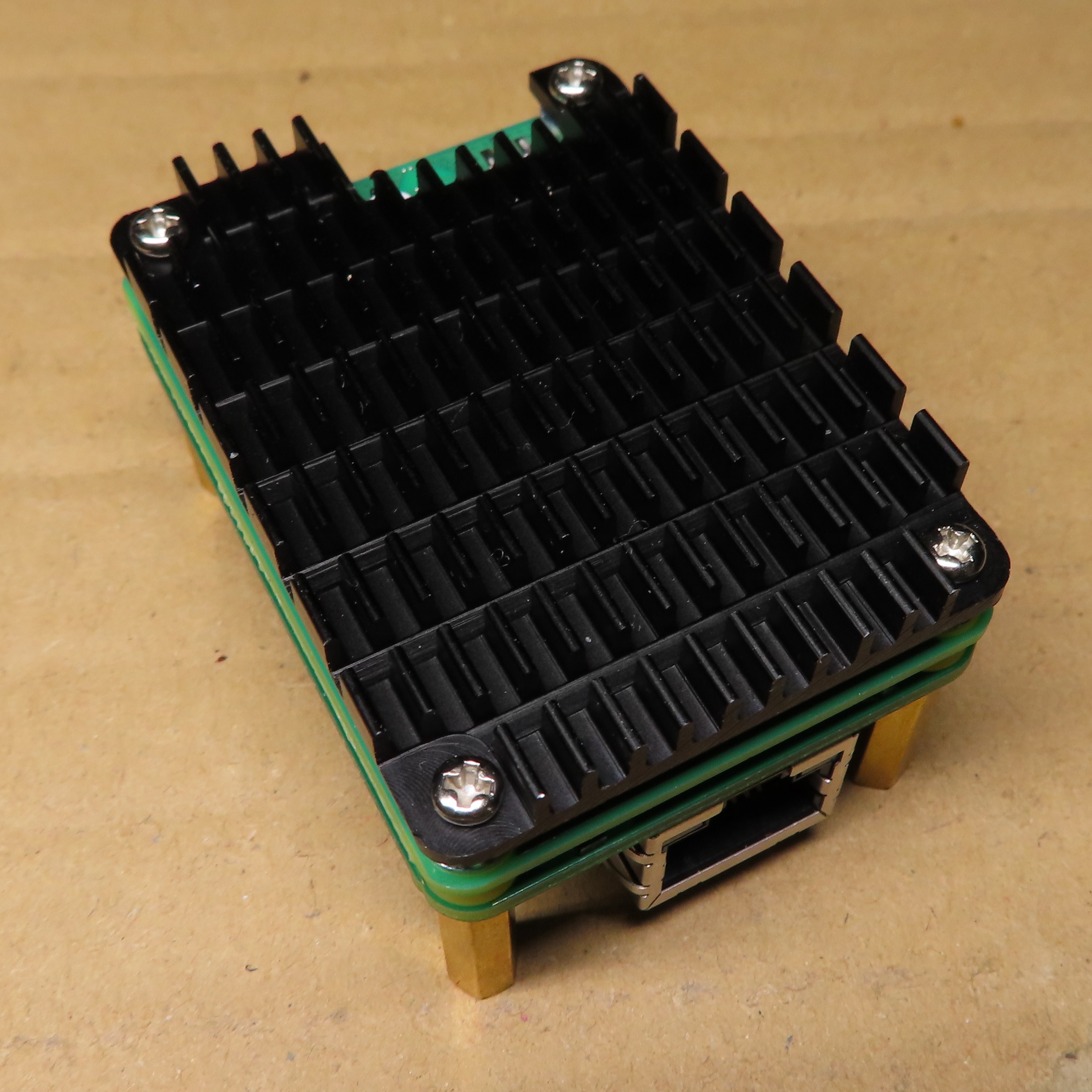
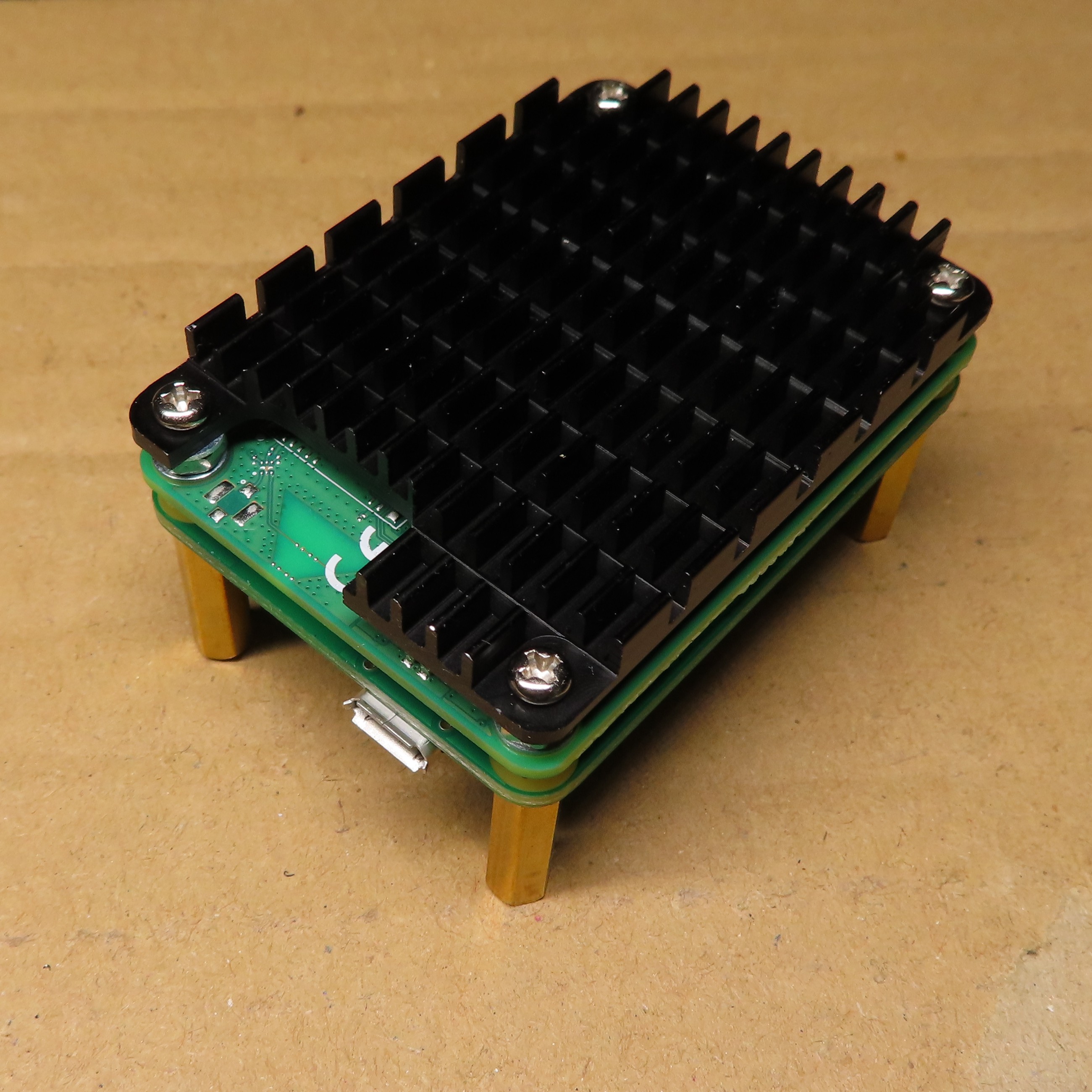
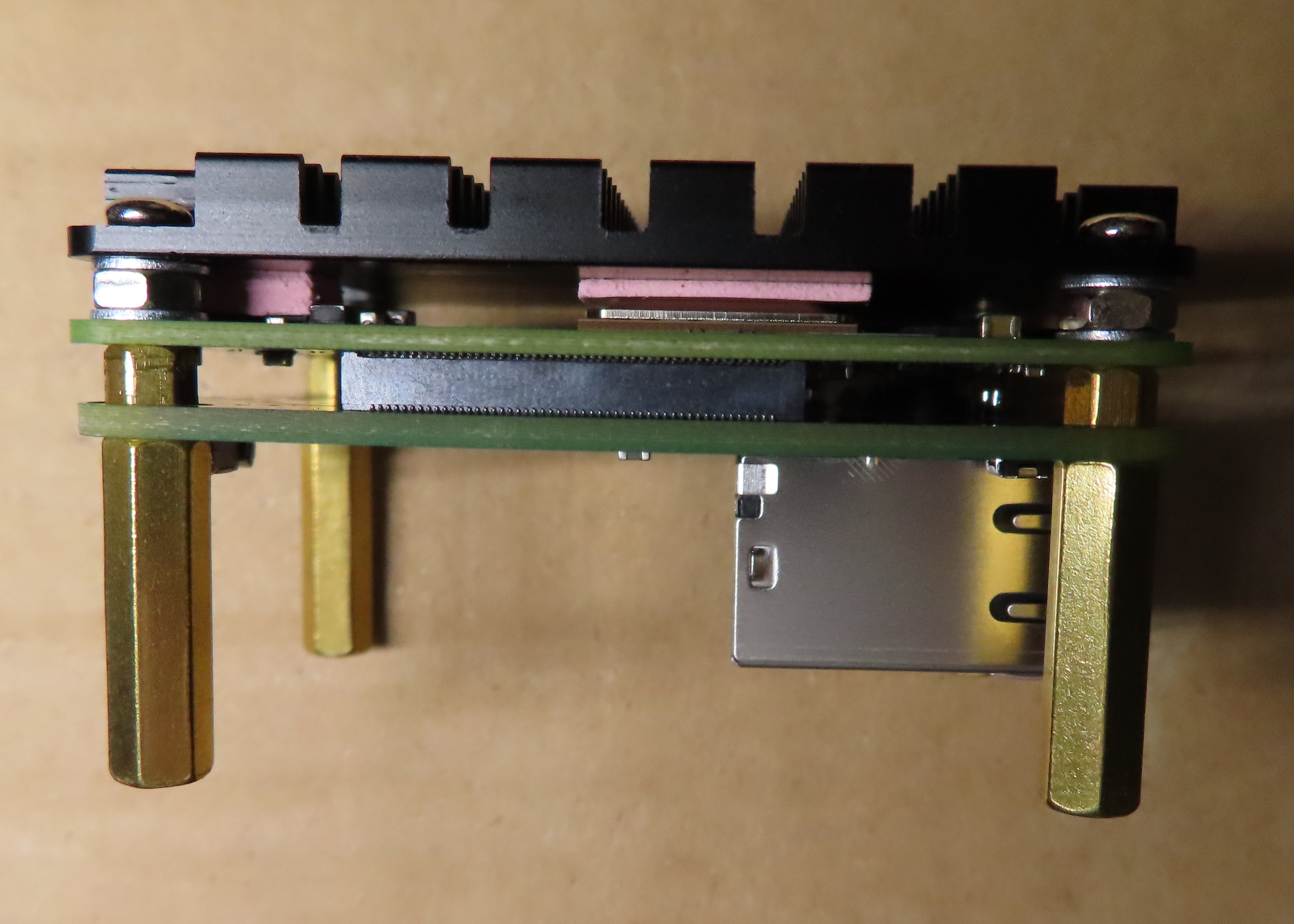
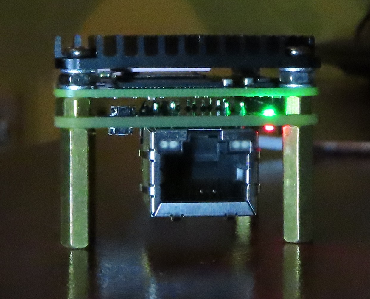
    If you have seen the photos in the previous update, then you know I mounted a heatsink to my board. For those interested in buying one themselves, this is a model by Waveshare, precisely this one. It wasn't as trivial as following the manual to make it look like on the photos, because I wanted to still have spacer under the whole setup. I ended up with something like this:

    This whole set of screws, washers and spacers is a mix of Waveshare set and whatever I was able to find. Finally I managed to do it like I wanted, so it is now standing on my desk and at the same time it should be a little bit colder. To be honest, I did not do any stress tests yet, so can't tell if it was worth the effort, but marketing materials looks promising. Maybe if I get more finished software stack, I will do my real world tests, to not make judgements based on stress-ng only, as it is never like the real environment.

    New front panel

    One of the goals of last PCB revision was to make the board more clustering friendly. While you still have to use Micro USB connector on the back, which is unfortunate, but this is how things are for now, everything else is now on a side, that can be called front. So, on this new front there is Ethernet connector, power and activity LED, power and reset buttons. This is how this new front looks like:

    Maybe it is not obvious from this perspective, but these two things left to the Ethernet connector are power and reset buttons. While playing with Alpine I had to use reset a lot and I can already say that it is not easy to use at first, but with help of toothpick, one can get used to it. In final setup, it should not be necessary to use any of these buttons anyway.

    Alpine Linux booted from network

    Finally, the most important part. My goal, when choosing OS for the cluster, I would like to build was to get something really lightweight. I already knew that there is a distro called Alpine that people use in-container. So, I decided to give it a try. It turned out Raspberry is at the moment supported officially, so no hacking should be needed to make it work. On official website, one can download special package for Raspberry Pi. Despite that official support, it wasn't immediately ready to serve via TFTP, so I had to make some small adjustments:

    1. First of all I extracted alpine-rpi-3.14.3-aarch64.tar.gz package to tftp directory, so my dnsmasq.conf could serve it. You can use the same config that I used for ordinary Linux before (don't remember whether it was Arch or Raspberry Pi OS, sorry :) ).
    2. In the extracted package, two files require modification. First is config.txt to enable UART, as SSH will not work at this point. So this is what needs to be appended to [all] section:
      dtoverlay=disable-bt 
    3. Second is cmdline.txt, as it is not configured for netboot, which is no surprise, as this is not the default way to boot OS. Try something like that:
      modules=loop,squashfs console=serial0,115200 ip=dhcp modloop=http://10.42.0.1:8080/modloop-rpi4 alpine_repo=http://10.42.0.1:8080/apks apkovl=http://10.42.0.1:8080/localhost.apkovl.tar.gz

      Note that 10.42.0.1 is my Linux system that will serve as TFTP/DHCP server, as well as HTTP server to give Alpine-specific files. By the way, its nice, you don't need NFS at all, when netbooting Alpine, which is rather unique function.

    4. Last thing to prepare is public_html that will serve those 3 files (apkovl will not exist for now, we will add it later). Modloop files can be found at tftp/boot/ directory, so let's copy them to public_html. apks are directly in tftp, copy them, too.

    5. Finally we have to start DHCP/TFTP and HTTP servers:

      sudo dnsmasq -dC dnsmasq.conf -i enp1s0 &
      darkhttpd public_html &

      This makes them run in background of current shell, so not exactly...

    Read more »

  • v0.2.0 boards arrived and work!

    Kamil Lorenc11/04/2021 at 18:08 0 comments

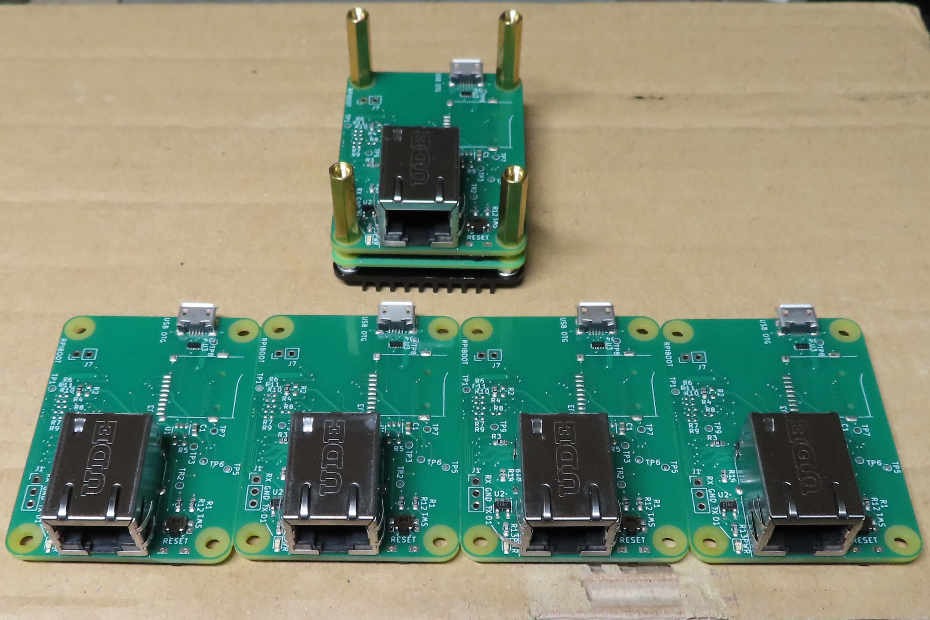
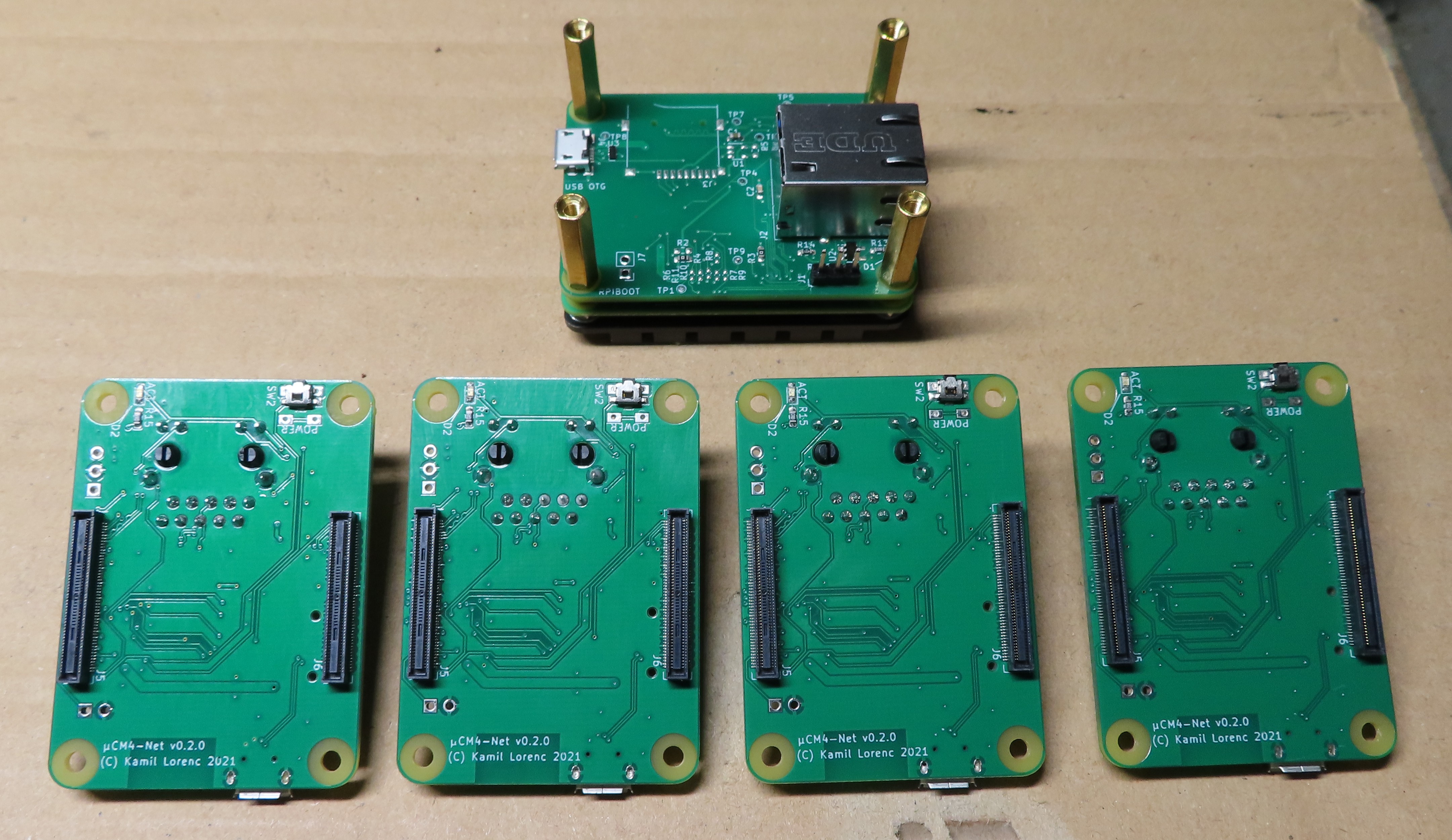
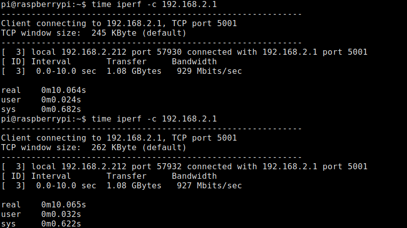
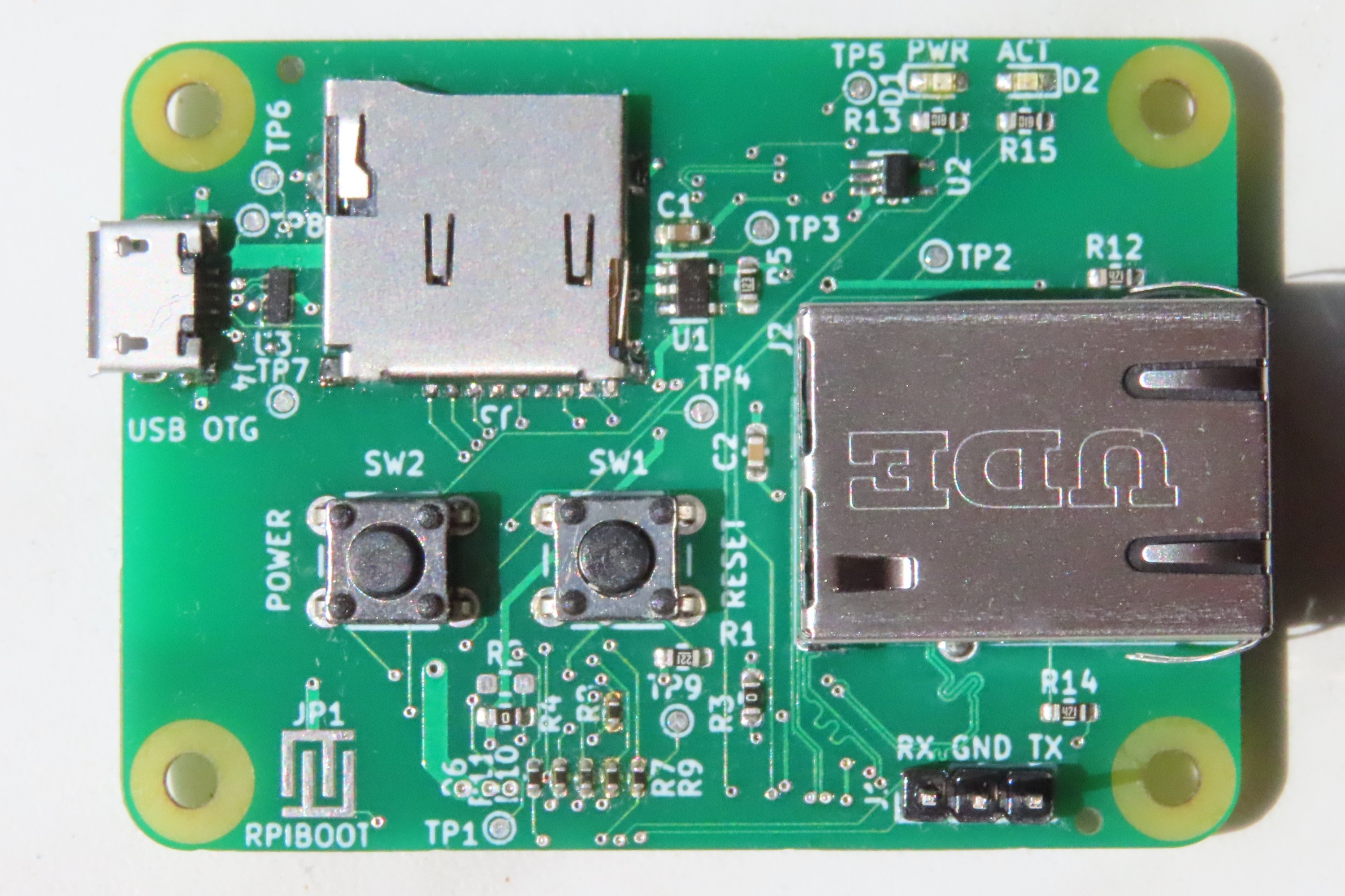
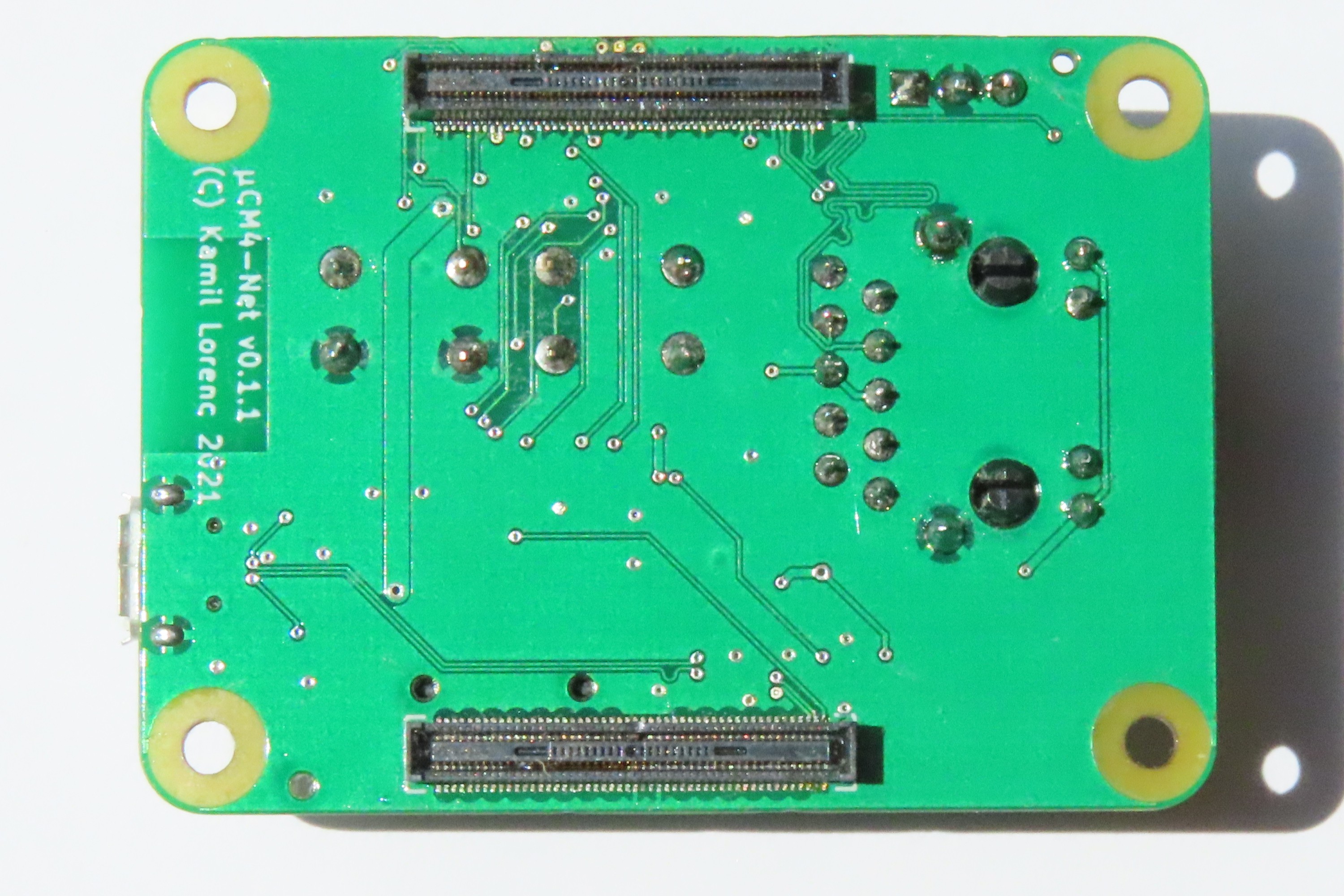
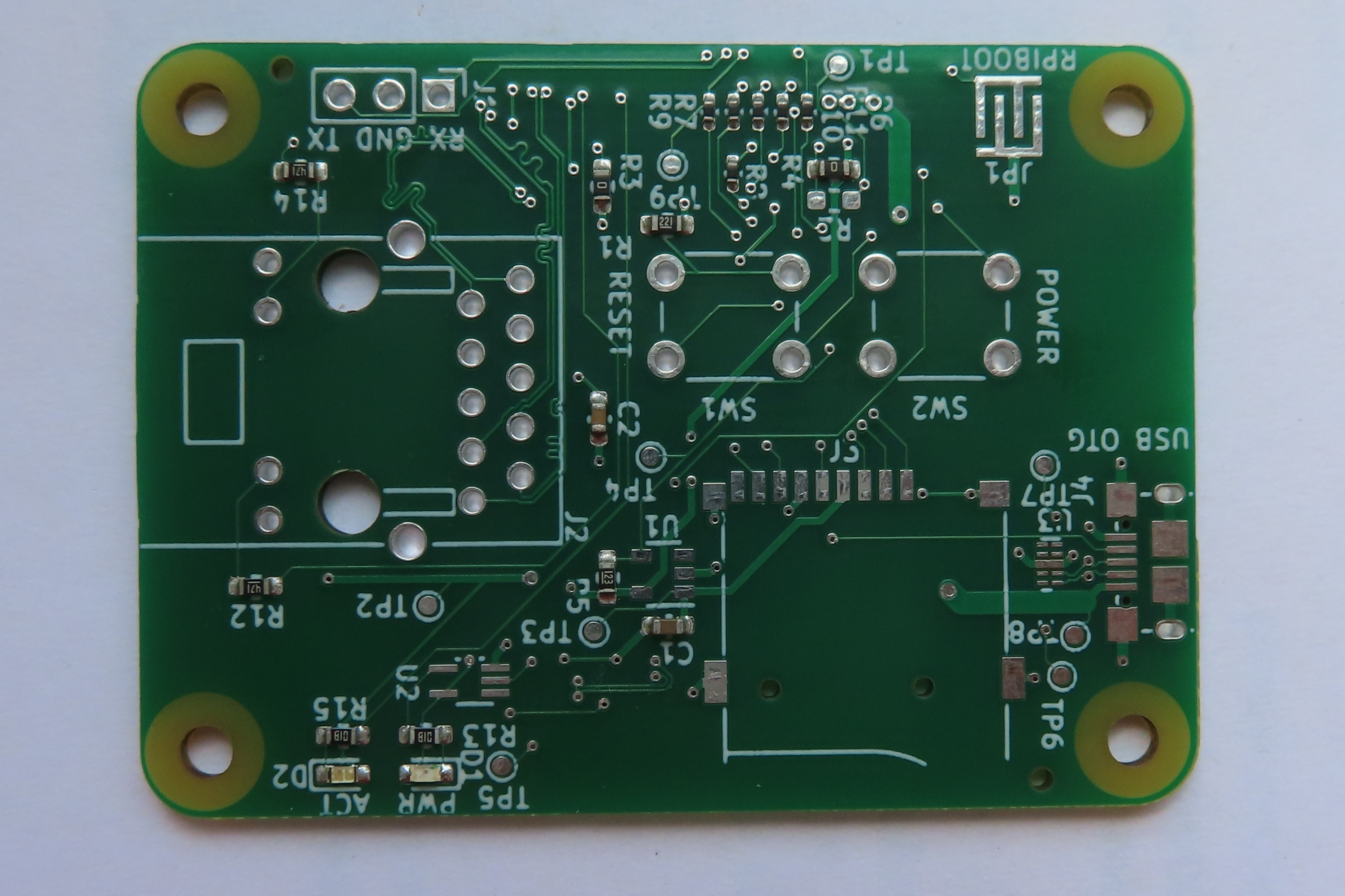
    Today, finally, after more than a month (last update was September 13) I received a package with 5 boards in 0.2.0 revision. I just finished testing one of them and till now everything works perfectly fine. I hoped for earlier arrival, but Chinese holidays in early October caused delay even to factory estimates. Fun fact is that I chose railway parcel as a shipping option, so now I know that maybe it is faster than ship, but air mail still wins in terms of time. Anyway, they are finally on my desk, so expect some news in the coming days. For now I can show you short gallery and obviously Ethernet benchmark, as this board is all about Ethernet, so it would make no sense without maximum throughput that BCM2711 can give me. Here it is:

    And below should explain why fifth board looks so weird:

    Finally promised iperf results to my laptop. By the way the same PC shared TFTP and NFS to netboot CM4 under test, as obviously boards came with no microSD connectors.

    For today this is all I have. I hope in the coming days I will be able to play with the boards a bit more.
  • New board revision, almost ready for manufacturing

    Kamil Lorenc09/13/2021 at 15:30 0 comments

    For the past weeks I got couple of questions about ability to buy a piece or two of my boards. I decided that I could try myself at manufacturing and offer such option in near future. At the moment I would like not to disclose any details as this is in quite an early stage. But today is for me quite a huge step in that direction. I ordered test batch of 5 pieces, fully manufactured, so I will not have to assemble anything myself. If this works, I will be ready to order any amount at the same factory.

    These boards are by the way in new version - 0.2.0, which, as numbering suggest, has way more significant changes than introduced with 0.1.1. On the other hand there is IIRC no modification to schematics, so less likely to make mistake that will make them unusable. This means that I am quite optimistic about this design. Still I am not so sure about all the other files I had to prepare for factory, as I am not very experienced with that, but we will see if this worked :)

    Getting back to new board. changelog is on Github, so those interested can read it and of course there is also full git log for real nerds :) Most visible change in this version would be replacement of buttons with smaller SMD ones and moving them near the same edge that is already occupied by Ethernet connector. The idea with this, and also moving LEDs to the same side, was to make it easier to handle in clusters, where I can imagine it is desirable to have full control of the board, while seeing only front side. This should be now possible. There are also a couple of other modifications, at least one of them as a result of chip shortage, so those willing to make board themselves should ensure they read BOM of the right version, when ordering parts. This is already updated for 0.2.0, here on Hackaday.

    And, after all this good news, there is still one bad news - PMICs, that are needed for microSD are still unavailable at usual, trusty suppliers, so there is no chance to handle Lite CM4s with SD boot - sorry, but there is little I can do. Having said that, I should mention that I am somewhat affected by that, too, as I had to order assembly without microSD support. Now, if I decide to start manufacturing, I would have to decide whether I should wait, or manufacture without microSD, so if you are interested in getting uCM4 for yourself, let me know your opinion. You can write comment, or contact me directly, so I will know better people's expectations and will be able to make the right decision.

    Anyway, next month will be just waiting, also for me, as there is not much to do in this topic before getting the hardware. And factory claims it would take them a month to assemble. And then a week or two have to be reserved, before getting the package at my door. So, if you can't wait to hear next update, let me know and spread the word. All this makes it more likely to get this board on your shelf!

  • Ethernet works again, even with netboot/PXE

    Kamil Lorenc08/07/2021 at 19:09 0 comments

    Today I have two small updates and two good news at the same time. I fixed Ethernet on my v0.1.1 board and just finished configuring PXE with this board. At the moment I am finalizing tutorial on how to netboot CM4 connected to uCM4, as it turned out to be less obvious than I thought.

    Getting back to Ethernet issues, this indeed turned out to be soldering problem. After reflowing both connectors, problems disappeared. Fun fact is that I was forced to do that, because I destroyed high speed connector few days ago, when disconnecting CM4. It turned out to be soldered so badly that I broke it, instead of disconnecting. Anyway, this forced me to fix the thing and in the meantime I checked that Hirose connectors could still be fixed, when pins fall off the connector chassis. And finally I learned how to solder them quickly and successfully, so if you are interested in getting some advice, let me know and I can consider describing it from newbie perspective (it seems that I am still lacking experience in soldering).

    Expect tutorial in coming days!

  • Netbooting Compute Module 4 in uCM4 carrier

    Kamil Lorenc08/06/2021 at 17:08 0 comments

    uCM4 was designed as a network device. It has Ethernet connector, which is the most important interface to outer world. And these days many devices, including our PCs can boot directly from network using thing called PXE. For uCM4 PXE would make Micro SD connector unnecessary. Luckily for us, for quite some time Raspberrys also can boot themselves from network. CM4 is not an exception here. But unlike ordinary Raspberry Pi 4, it is a bit more complicated. Let me present how to achieve that with CM4 and uCM4. I would not be surprised, if you got here while looking for a way to do that with CM4 and official CM4IO, so I will try to mention the differences between uCM4 and CM4IO in that matter. Enough of this introduction, let's start!

    What you need

    Basically, there are few Git repos to clone to allow you to get started. Clone them by issuing following into your system (this does not necessarily has to be Raspberry and keep in mind that for uCM4 you will have to be able to power whole system from that device, so my advice is to use PC, or alternatively device with active USB hub in the middle):

    git clone https://github.com/raspberrypi/rpi-eeprom.git
    git clone https://github.com/raspberrypi/usbboot.git

    If using uCM4, you also gonna need tweezers, or something similar to short JP1 jumper. I know, this is one of the not-so-successful parts of the design and is going to be subject to change in future.

    What's more, on the system that will serve as server for Raspberry to communicate with you have to install DHCP, TFTP and NFS servers. In case of Arch Linux these can be provided by dnsmasq (DHCP+TFTP) and nfs-server (NFS). In other distros names should be similar.

    Getting software ready

    Fortunately programs in rpi-eeprom repo are in fact scripts, so nothing to do there. But in usbboot, you actually have to compile. Luckily this is as simple as calling:

    make

    As a result you should get rpiboot binary directly in repository root directory.

    Getting right EEPROM firmware image

    This is harder part. From what I know, it is not possible to simply change configuration in EEPROM. You have to flash full firmware image with changed configuration. What I did was to simply copy recovery firmware from usbboot repo, but in fact you can use any version from rpi-eeprom repo. The one that I chose is pieeprom-2020-10-02.bin, so this is how I will refer to it later.

    Preparing configuration

    As you have your pieeprom image, you can go to usbboot repo and create new directory for our network configuation. Copy your EEPROM image to this new directory. Don't change the name for now, we will make use of this improper name later. You will also need bootcode4.bin from recovery as first stage bootloader, I guess. Now it would be nice to get current boot.conf from CM4 that we are going to reconfigure. While in Raspberry Pi OS, you can simply call:

    vcgencmd bootloader_config

    And save the output as boot.conf of your PC. You should get something like me:

    [all]
    BOOT_UART=0
    WAKE_ON_GPIO=0
    POWER_OFF_ON_HALT=1
    DISABLE_HDMI=0
    BOOT_ORDER=0xf41

    At this point the only change for us to do is to replace 0xf41 with 0xf21. Why? Here is the documentation from Raspberry Pi Foundation. Basically this 4 meant USB-MSD and 2 means NETWORK, so we create order like SD->NETWORK->RESTART.

    Updating EEPROM image with new config

    We have our configuration, but not in a file used by rpiboot. So, we have to insert it, yet. And this is why we really needed rpi-eeprom repo. First, we need to add it to our PATH:

    export PATH="$PATH:/path/to/rpi-eeprom"

    Then we have to call rpi-eeprom-config to modify pieeprom.bin:

    rpi-eeprom-config --config network/boot.conf --out network/pieeprom.bin network/pieeprom-2020-10-02.bin

    This creates the file that rpiboot expects - pieeprom.bin. Finally, we need to create signature for our image. Let's start by copying template from recovery directory. Then call sha256sum to see current hash:

    cp recovery/pieeprom.sig network/
    ...
    Read more »

  • Build completed

    Kamil Lorenc07/31/2021 at 12:12 0 comments

    Yesterday I was able to finish soldering the board. Here you can see it during first test with CM4 connected to power supply:

    As can be seen it went well, so I went on. This is how finished board looks like:

    And bottom:

    Generally, differences between this and previous board are almost unnoticeable and this is how it should be. It was meant to be, let's say, "bugfix" release. Existing problems indeed seems to be fixed now. In the final board however I encountered new issue - Ethernet does not want to negotiate 1 Gbps, what is unfortunate and regression since the first iteration. But I suspect it is build related, as the only modification around Ethernet connector and traces was diameter of shield mounting hole, which I believe did not cause this issue. Anyway I am going to investigate this and hopefully will be able to either fix it, or assemble another board to check if it persists.

    For now I can sum up this iteration as (only small - due to Ethernet) success. Next goal is to set up some software in the direction of clustering and eliminating Micro SD card. I am also considering doing some modifications on the board, especially location of LEDs, as these are not exactly convenient for mounting in something like racks, what might be a problem for some people. And of course there is still supply chain problem for which I do not have any workaround, at least for now. I will keep posting updates in case of any news in the project.

  • New boards arrived

    Kamil Lorenc07/29/2021 at 12:16 0 comments

    Today just a quick update. Last time I wrote that I ordered new boards. Today I received the package. After quick check, everything looks fine. One unknown was Ethernet connector, where one mounting hole was to small for easy assembly. It this revision it is way better and for me the risk of damaging the connector during assembly is eliminated.

    Here is the board that I got:

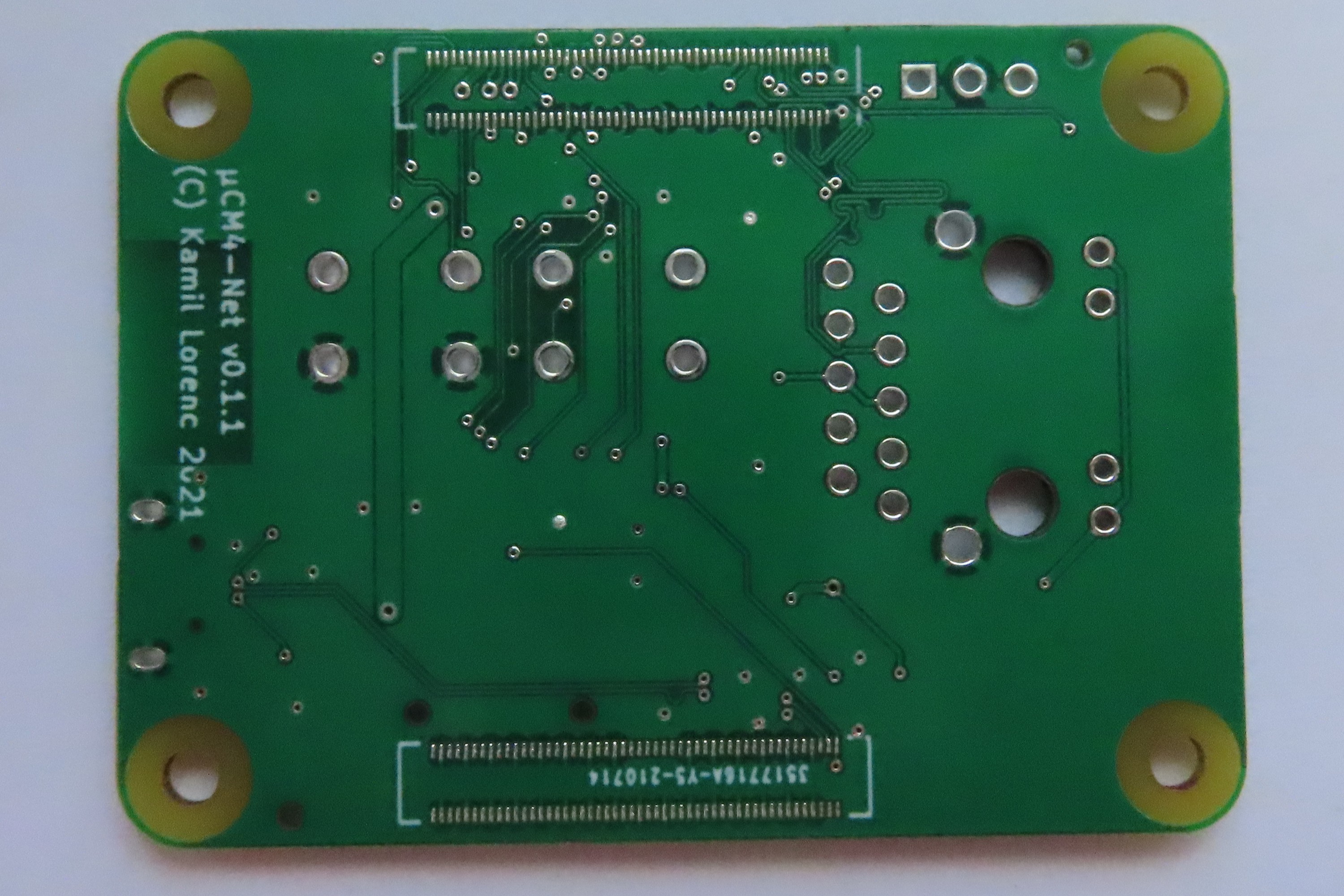
    And back of it:

    As you can see it is already in version 0.1.1. I did not order assembly of U1-U3 ICs to save some money. If you want to reproduce the design, it should be enough to upload files available on Github (as assets to this release) and order (by default JLCPCB should offer to assemble U1-U3, if available).

    Now the plan is to have it assembled, up and running till end of next weekend. Expect another update soon!

  • Fixed board revision sent to fabrication

    Kamil Lorenc07/13/2021 at 16:03 0 comments

    Increasing interest in my project motivated me to finally make next revision of PCB. Let me show you version 0.1.1. This is solely bugfix version and gets rid of most of the mistakes that I made on first iteration. There is nothing new, though. Goal here is to end up with a board that I can safely solder myself and use for further testing, possibly making 2 additional boards and trying some experiments in setting up Kubernetes.

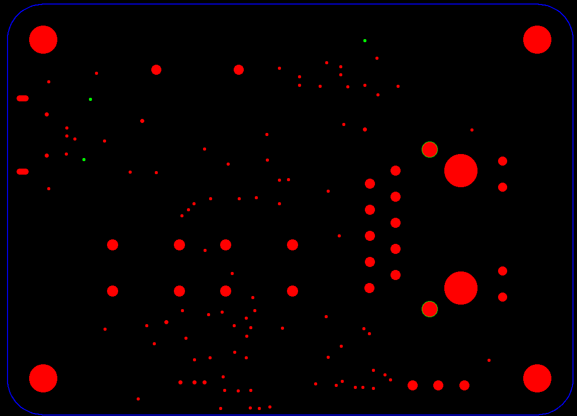
    Anyway, I fixed power rail width error, increased diameter of Ethernet shield hole, so now it should be way easier to place and this time I didn't forgot to regenerate drill files :) so now testpoints for USB should be on its place, too. Log of important changes is now on Github release page and obviously full log of changes is in Git's commit history. Here is the visualization of these few changes. First are drills (green is new, red is old):

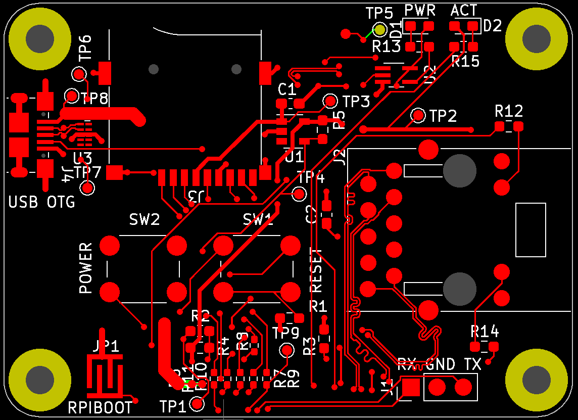
    And here is the complete board with new traces also in green (you don't see removals here):

    As can be seen, changes are very subtle, but on the other hand, necessary.

    Now, I have to wait few weeks before my order is produced and delivered. Then it will for sure take few more days to solder it properly. I hope this time will be better, as last time I didn't have enough soldering experience to do it right on first attempt, what finally took me couple of evenings to complete. In the meantime, maybe I will try to do some software development, as my plan was to boot CM4 with PXE, or something similar, so I will not need Micro SD card anymore. And this would be good improvement in the direction of setting up everything automatically for Kubernetes.

    I also developed BOM and CPL files for SMT assembly a bit further, so in theory it is now possible to order assembly of all 3 ICs present on board - means ESD protection of USB, PMIC for SD card and LED buffer. I even attempted to do so for connectors, too, but with that I failed for now, so this is an exercise for the future due to wrong middle point on my custom footprints. During playing with that I noticed that RT9742CGJ5F (mentioned PMIC) is at no stock whatsoever. Even more disturbing is the fact that there is only one shop I could find, where they claimed to have some and with other Richtek-made PMICs it is not much better, or acutally all of them are at zero stock on LCSC. Fortunately, I still have 9 of the right ones, so for myself it is not a problem, but I can imagine someone trying to reproduce my design and failing to do so due to that. Also this would make any attempt of mass production impossible for the moment, unless redesigned to use different part. It is not a surprise for me, as IC shortage was first heard in context of nothing else, but PMICs.

    PS. If you know any PMIC that can be used instead of the one mentioned and which I can easily source on LCSC, or any other non-Aliexpress-or-Taobao place, let me know. I can consider using it instead of the now unobtanium Richtek.

  • More Ethernet testing

    Kamil Lorenc05/27/2021 at 06:36 0 comments

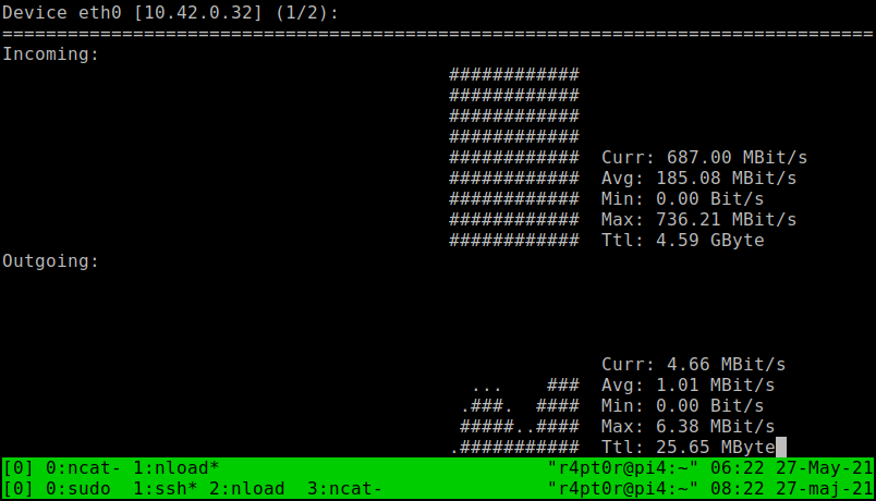
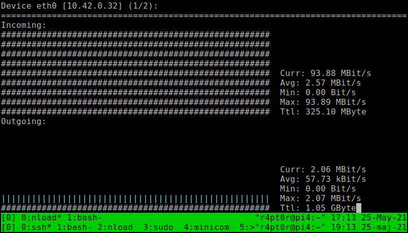
    Today, finally I was able to set up stable Gigabit Ethernet connection to my laptop. Did some quick test by sending random file from my laptop's SSD to CM4 and storing in /dev/null. Here is the result measured by nload:

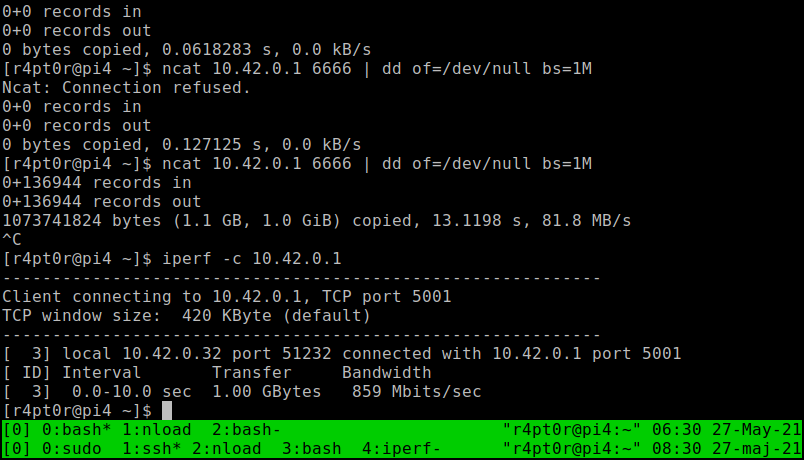
    And I got quite nice ~700 Mbps. I still hope this is not maximum for CM4, but SSD was bottleneck this time. Let's see what iperf is gonna say. And it showed this:

    By the way you can see dd counting previous attempt. So, here we have ~860 Mbps. This I can believe in.

    Then the summary is that my board does its job nicely. I played quite a lot with trace length matching tool in KiCAD to make sure that all traces carrying Ethernet signals are of exactly same length. I'm curious what would be the result if I ignored that. But I think that spending money and time on next batch of test boards is not worth it :)

  • Test of Ethernet connection

    Kamil Lorenc05/25/2021 at 15:54 0 comments

    uCM4 carrier board was designed with network projects in mind, so the most important thing to check is how fast the internet connection could go.

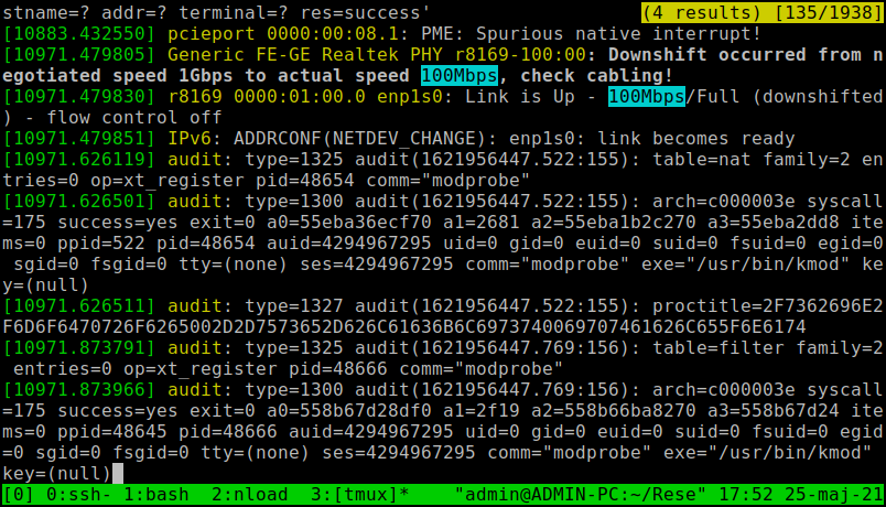
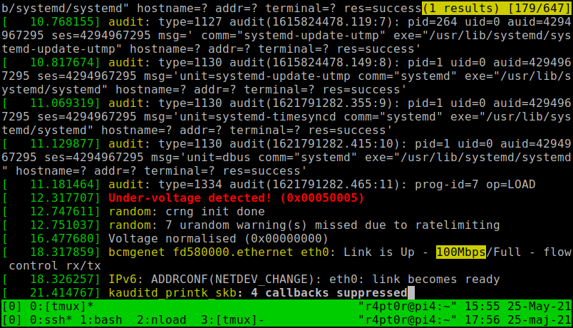
    Today I did some quick tests on that matter. First test went rather unsuccessful, as definitely my laptop, that is sharing internet to CM4, opened connection at 100Mbps. I tried with few cables that claim to be Cat5e, but all of them worked as bad as first one.

    My PC suggesting that cable is the issue and synching at 100 Mbps:

    CM4 only tells me that I got 100 Mbps:

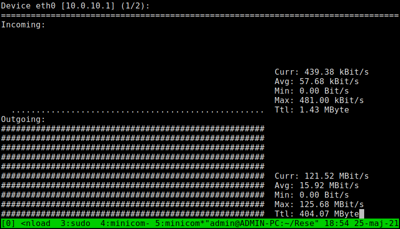
    Despite being unlucky with port speed, I tested nload to see how much do I get on 100 Mbps link. It showed ~90 Mbps. Nice.

    After trying 3 cables I decided to change tactics. I reminded myself that I have old Wandboard PICO-PI-IMX7 lying around and collecting dust. Fortunately it stills has working OS flashed, so let's try that:

    100 MBit/s crossed, so first small success.

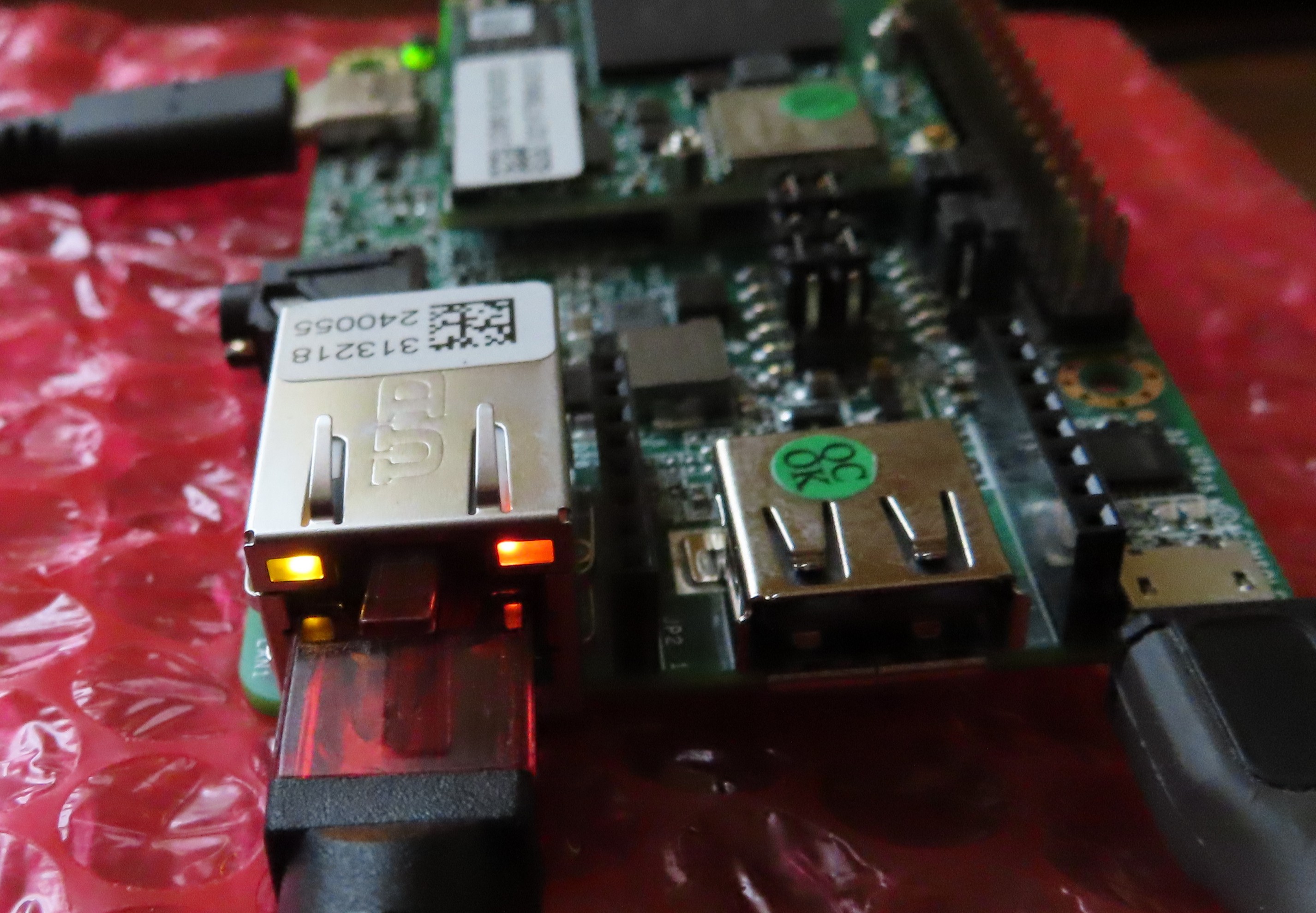
    Wandboard clearly indicates 1 GbE link with its orange LED, instead of usual green, that I saw just a moment before with different cable:

    I wonder why they didn't do same on Raspberry Pi. Even if I used same UDE connector on my board, there is no signal indicating 1 GbE, instead of 100 Mbps, AFAIK. Weird.

    Next time, I will try to test connection from CM4 to Raspberry Pi 4, as I suspect Pico Pi is bottleneck here. At first I tested connection from Pico Pi to PC and got almost same ~120 MBit/s. i.MX7 is not the newest SoC, so it is not really a surprise, you can't get more from that. However, before testing Pi4, I have to prepare another OS, as till now I used card borrowed from my Pi4, so can't do that quickly, unfortunately.

View all 12 project logs

Enjoy this project?

Share

Discussions

Laurent Geindreau wrote 09/20/2021 at 15:27 point

Hi,
For my part, I plan to use only CM4 with integrated flash. So I don't need the SD connector and its management components.
Regards

  Are you sure? yes | no

lucdig wrote 09/07/2021 at 06:14 point

Hi, I use my Compute Module 4 with eMMC boot, my board has a switch to enable/disable eMMC boot so I can use rpiboot on it and flash the eMMC with a new OS image. Will you put a switch on your minimal board?

  Are you sure? yes | no

Kamil Lorenc wrote 09/09/2021 at 08:54 point

I thought about that after you wrote this comment and I decided to use 2-pin header instead. I don't plan soldering it in any of my boards, as I don't need it very often, but in my case should make shorting with tweezers easier, so seems to be win-win solution.

  Are you sure? yes | no

Laurent Geindreau wrote 08/23/2021 at 14:29 point

Simple and efficient integration. We have plans to use it in the state, also interested to find it on the shelf.

  Are you sure? yes | no

darren.conway wrote 08/19/2021 at 11:20 point

Are you planning to release the design details under CC by 4.0?

  Are you sure? yes | no

darren.conway wrote 08/11/2021 at 11:11 point

What is the power consumption of this board under different operating conditions?

eg.  When Idle (minimum power used)

When running usb full speed

When running Ethernet full speed

Maximum power used


  Are you sure? yes | no

jeremy lee wrote 08/08/2021 at 01:43 point

i know you have been asked... but I want to buy. do you plan on producing any for sale?

  Are you sure? yes | no

Kamil Lorenc wrote 08/08/2021 at 06:21 point

We will see :)

  Are you sure? yes | no

mike-barlow wrote 08/04/2021 at 22:11 point

Thank you for this.  Could you tell us if you used the standard RaspberryOS with adding a ssh file to have access to this?  If not, could you please email me what changes you made?  Seeed studio will make as few as 5 of these.  I would be interested in getting a few with and without sd card.  mike@iaq-cpr.com

  Are you sure? yes | no

Kamil Lorenc wrote 08/05/2021 at 09:08 point

Sounds good. Did not know that Seeed can make boards. Will check that out and see how much does it cost.

  Are you sure? yes | no

gregid wrote 07/28/2021 at 01:03 point

Is there any chance for the PoE version? I have unused PoE switch that I would like to use for potential cluster rather than purchasing additional power adapters. 

Other than that - brilliant idea!

  Are you sure? yes | no

Kamil Lorenc wrote 07/29/2021 at 12:07 point

Thanks! Yes, there is a chance. But I cannot promise anything. I imagine that in final revision there is only Ethernet connector, so no SD card and no USB. Of course they could still be left as optional. But for now it is hard to say when I will do that, as there are other things I have to focus on in the coming weeks.

  Are you sure? yes | no

MisureMeccaniche wrote 07/07/2021 at 05:55 point

Hello, where is possible to buy one pèiece for testing? Kind regards.

  Are you sure? yes | no

Kamil Lorenc wrote 07/11/2021 at 18:02 point

Hi. Thanks for interest. For now it is just personal project. But, if the interest in producing these would be high, maybe I can consider manufacturing them. For now, next step is to make prototype of new hardware iteration to eliminate problems that I found on the first board. So, stay tuned!

  Are you sure? yes | no

gplab-ide wrote 07/02/2021 at 11:45 point

What's the license of uCM4 design?  Can I make PCBs according to the uCM4 design and use the PCB commercially?

  Are you sure? yes | no

Kamil Lorenc wrote 07/02/2021 at 14:39 point

Give me few more days to figure this out. I don't know anything about licensing hardware, but I would like to allow anyone to do anything as long as he/she preserves the copyright notice and license. Something like MIT, but I'm not sure how well it fits hardware. That's why it is still not here.

Edit: I have just set license to CC BY 4.0.

  Are you sure? yes | no

gplab-ide wrote 06/11/2021 at 01:03 point

It is useful for building a raspberry pi cluster

  Are you sure? yes | no

Kamil Lorenc wrote 06/12/2021 at 18:53 point

Exactly. My idea was to play with this kind of stuff on Raspberry, that is why I designed this board.

  Are you sure? yes | no

Similar Projects

Does this project spark your interest?

Become a member to follow this project and never miss any updates