On my earlier Landbeest project, the robots legs gets moved by a scotch yoke mechanism that turns rotation into reciprocating linear motion.
For this to work the main gear needs two cranks, offset at an angle of 90°. Each crank moves a separate piston rod. Each of which connects to an opposing pair of legs.
To achieve the best mechanical stability the cranks should be mounted on opposing sides of the gear. Well, that's my conjecture, but I think that's right. Besides, that also makes for a more compact mechanism. Alas this is not possible since the piston rack moves past the center of rotation at every turn. With racks moving on both sides, there would be no side of the gear from which to fit it on an axle.
With Landbeest, I instead ended up with a two story cam shaft on top of the main gear. That setup worked well enough. It's just that it's bulky, hard to print, not very strong and not very elegant. I felt for sure a better solution had to be out there, but I didn't have the time or energy to pursue that notion. Also I was still working with TinkerCad at that point, so I knew any major change in design meant committing to a substantial time investment.
By the time I resurrected the project as Tardygrade, I had become proficient enough in FreeCad, and felt I could devote some time to experimentation and trying out more complex designs.
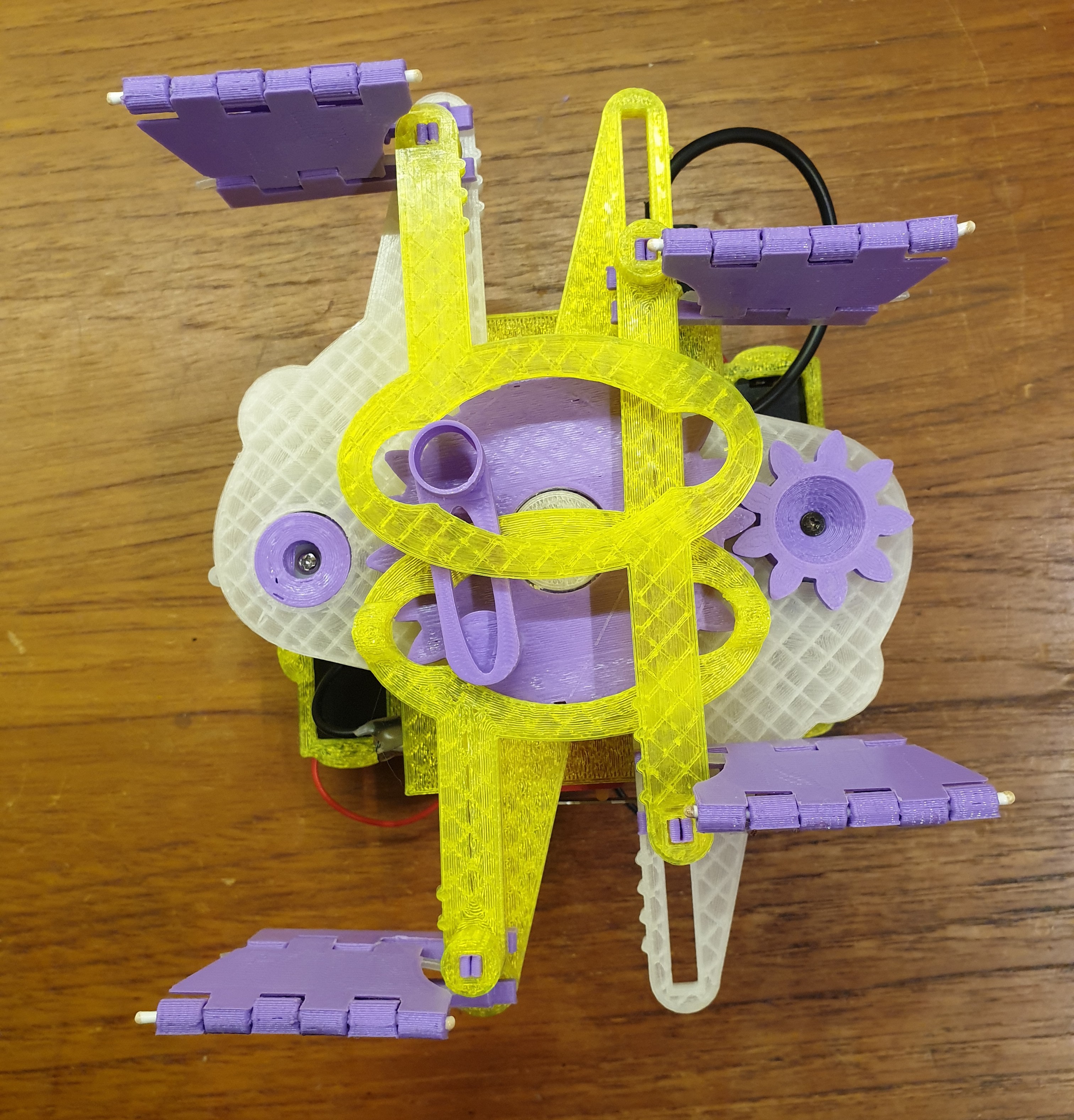
I decided to ditch the scotch yoke in favor of the Reuleaux triangle. I used to be dimly aware of that concept, mainly for its use in the Vankel engine. But if you browse the Wikipedia entry you'll find it's used in all sorts of stuff. For this application the triangle acts as a cam, with the rack as follower. The rack will still not clear the gear axle entirely, but that can be mitigated by adding an axle-sized indent on each side of the rack groove. This works as long as the rounded sides of the cam are wide enough to clear those indents unimpeded.
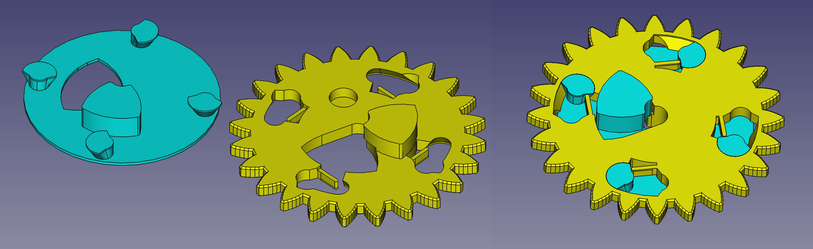
Now I had a solution that worked in concept. But how to print the friggin' thing? A gear with cams extending from both sides would a require a big slab of support between it and the build plate. That would be unacceptable, since both sides of the gear needs to be smooth in order to minimize friction against other moving parts. And I was under a self-imposed design constraint of avoiding glues or screws in the robot assembly.
Let's skip to the solution. Basically the gear prints as two part which gets joined permanently by some fancy twist-snap action. One part makes up the bulk of the gear, while the other part just acts as a platform for the opposing cam. Each part sports one flat, featureless side for hazzle-free printing. Since the build plate facing side of each part ends up facing outwards on the assembled gear, friction shouldn't be a problem.
The gear assembly has a built-in slot for a neodymium magnet. As the gear turns, the magnet gets detected by hall switches on the PCB above it. This positional information is necessary for the μC to execute the correct sequence of servo movements for walking and turning properly.
Footnote: While researching I stumbled over a recent master thesis on another robot walker mechanism that makes use of the Reuleaux triangle. Incidentally that mechanism looks identical to a Soviet era film advance mechanism showcased in the Wikipedia article. I just found that amusing. Not to throw any shade on the authors who thought of a new use for it. I guess in the world of mechanical linkages, not much is new under the sun.
Discussions
Become a Hackaday.io Member
Create an account to leave a comment. Already have an account? Log In.