 teru
teruThis is successive project of http://ktmizugaki.so.land.to/ele/wifi_voice_clock.htm .
While that clock is working perfectly for two years, I broke LCD and decided to upgrade project instead of replacing broken LCD.
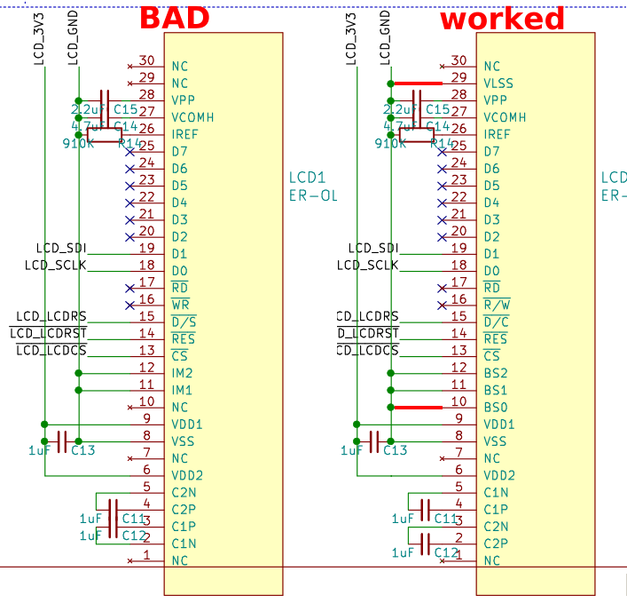
The challenge for me is using OLED. I also tried to fix some of broblems and reduced width slightly.
featrues
- Wakeup Alarm at configured time
- Synchronize clock with NTP protocol over WiFi
- Say time with button push
- Show clock with button push
- Support LiPo battery and can charge battery
- Deep sleep to reduce power consumption
- Check battery to prevent complete discharge
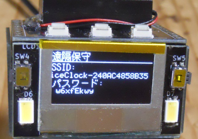
- Web UI for configuring clock
structure
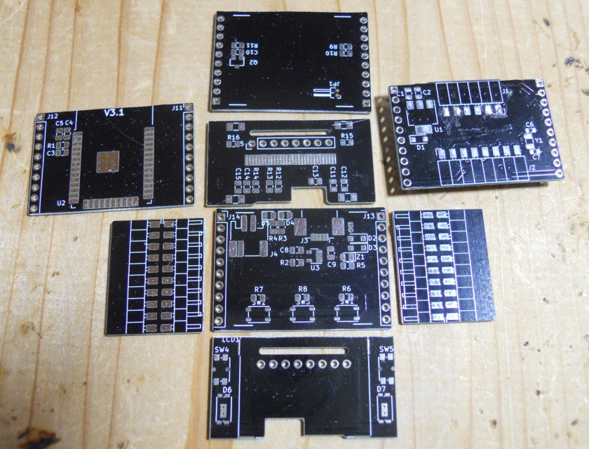
Clock consists of 7 boards.
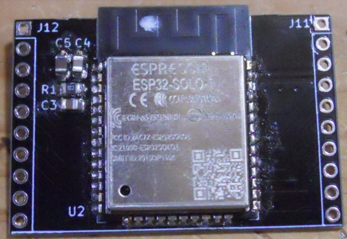
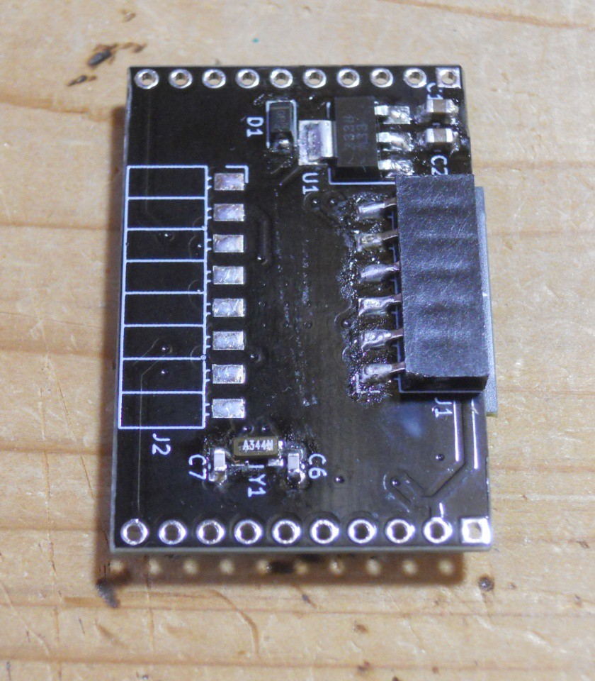
- MCU boards
This board is center of clock, enclosed by other six boards.
ESP32 module, 3.3V regulator, 32768Hz crystal. - PSU board
This board is bottom panel and has power related components.
PH connector for battery, mini B USB connector, charger IC and charge indicator LEDs - IO board
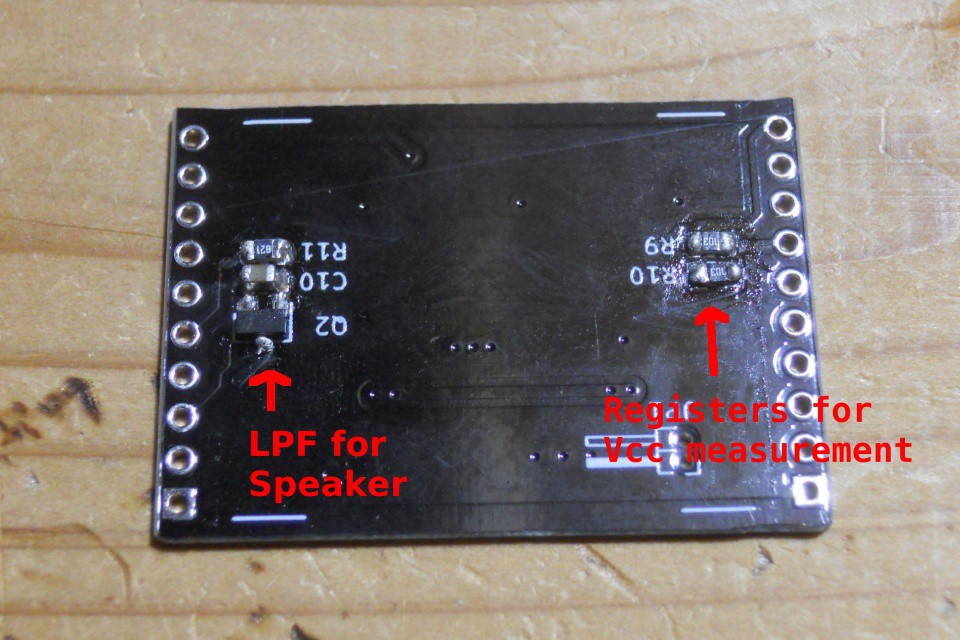
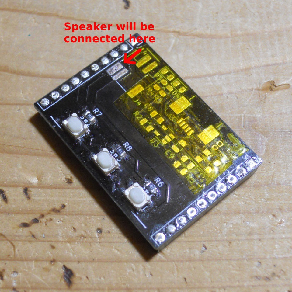
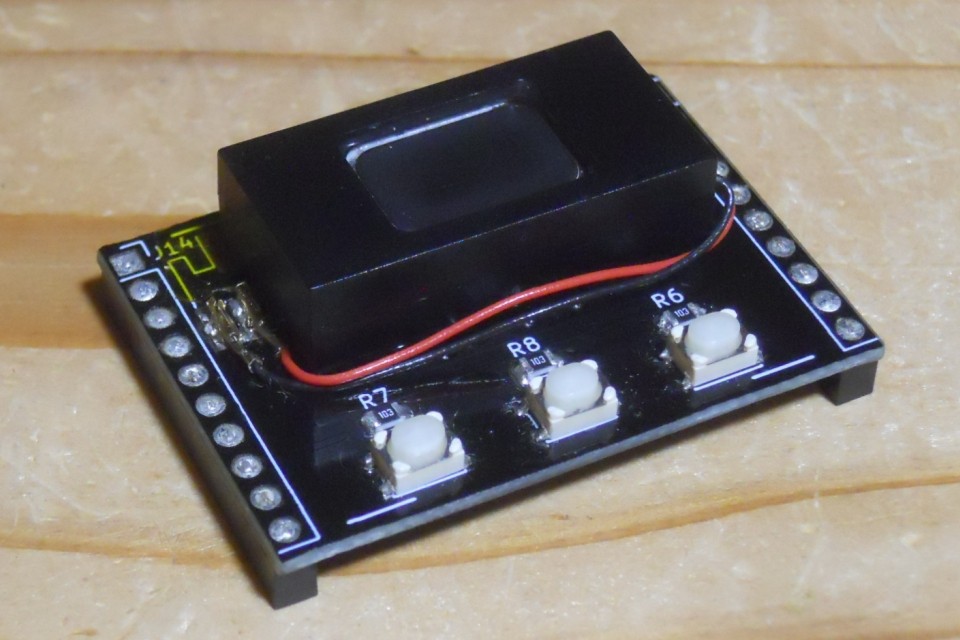
This board is top panel with switches and a speaker.
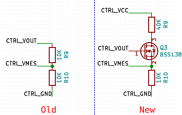
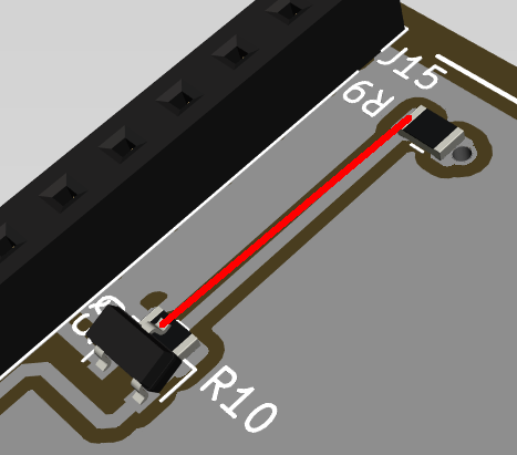
Also it has resistors to measure input voltage. - display board
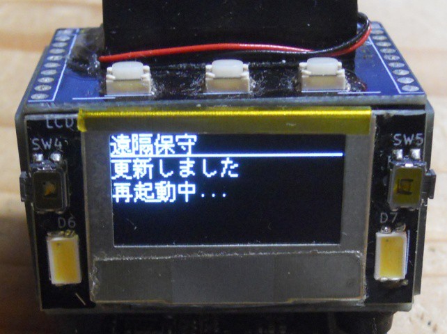
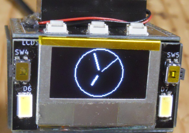
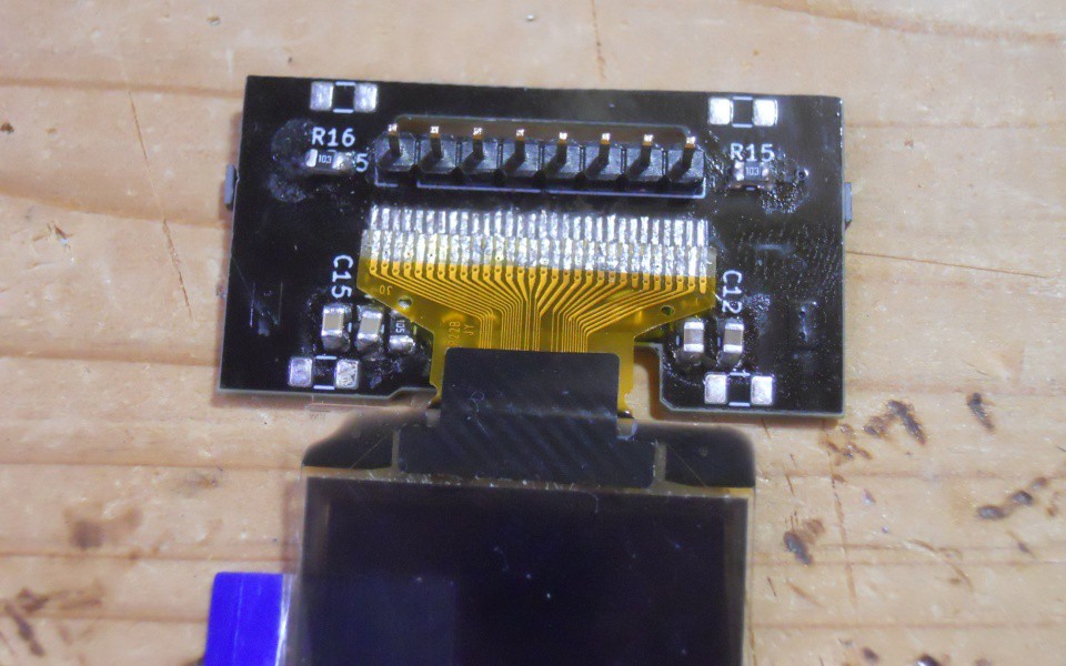
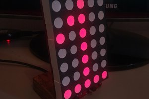
This board is front panel with OLED dislay.
I added two LEDs to just fill space. - two side panels
These boards connects PSU board and MCU board (both electrically and physically) - back panel
Just a panel, no circuit on this board but has holes so that USART and reset circuit can be connected to MCU board.


 danjovic
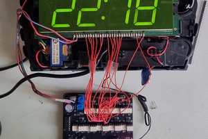
 zst123
 Patrick Graham
 Hulk
Hulk