 UFRJ-Nautilus
PWM Signal Control
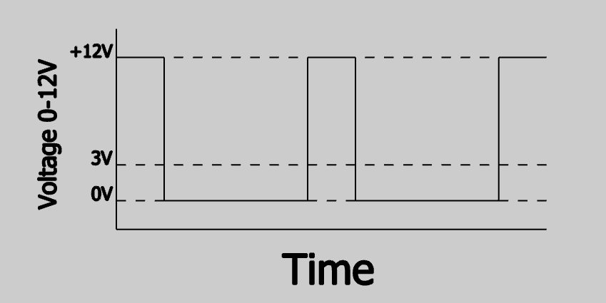
The PWM (Pulse Width Modulation) signal is a way to control the power of components. Let's say we have a switch that turns on and off when turned on delivers all available power, but when turned off it delivers no power. Suppose we have control of the time the switch is on or off, so we will also have control of the power that reaches the component. For example, if we have one switch turned on 25% of the time and the rest turned off, we will have an average 25% of the time with power and 75% without power, thus the power applied to the component will be 25%.
Get SMT Coupons: https://jlcpcb.com/RTA
ESC
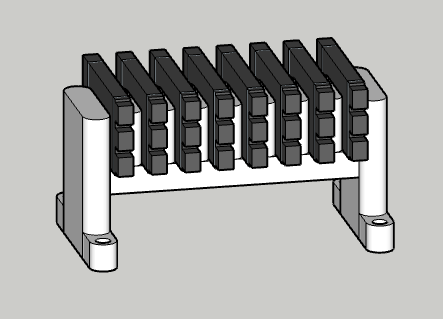
The ESC (Electronic Speed Controller) is responsible for applying the PWM signal to the thrusters, thus controlling the speed. It has two variations, Brushed (with brush) and Brushless (brushless). The ESC to be chosen depends on the thruster used, currently the AUV uses brushless three-phase thrusters, only the ideal for the AUV is Brushless. The difference between the two ESCs is that Brushed only uses the PWM signal to control the power of the thruster, while Brushless uses the PWM signal together with a microcontroller built into the ESC, with pre-defined software to trigger in sequences of coils. They are mechanically coupled to the board through 3D printed support.
Protection System and Current Sensor
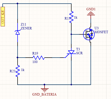
To avoid problems with current surges and short circuits, we made the implementation of a protection circuit for each thruster. The system uses components such as mosfets, resistors, bipolar diodes, zenners and SCRs.
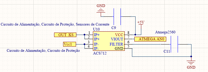
In order to have control over the currents that go to the thrusters, we have current sensor circuits, which makes use of IC (Integrated Circuit) ACS712-30A, being able to read up to 30 amps. The collected data are collected by the atmega 2560 microcontroller.
Communication and Consumption
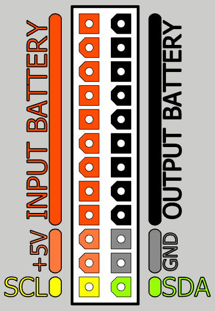
The aforementioned systems require high energy consumption, for this reason the board counts with two 24-pin ATX connectors, in order to support the energy demand, being one used only for power supply and I2C (Inter-Integrated Circuit) communication. I2C is the protocol used to communicate with Nvidia Jetson (Central board, in charge of operating the AUV), the second connector communicates with the thrusters.
Usage Example
Let's say the AUV needs to travel a distance, in a short period of time. If it only had a fixed speed, it wouldn't be able to complete the journey in time, or it would be too fast, as a consequence the AUV would have no control over its route and the detour of obstacles. Having the use of the propeller plate, which is responsible for control the speed and protect the same, there will be more flexibility when it comes to completion a path, being able to decelerate and make the contour if you see an object or accelerate necessary case.
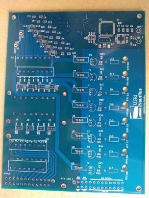
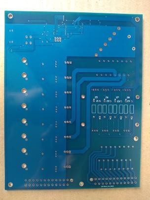
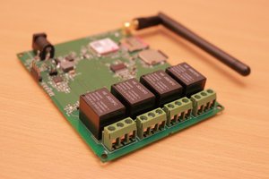
For our AUV project, we are using the amazing JLCPCB thruster board! Here are some pictures of our board:
A big thank u to JLCPCB
$2 for 1-4 Layer PCBs.
Get SMT Coupons: https://jlcpcb.com/RTA
 raviypujar
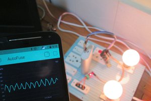
 Animesh Chattopadhyay
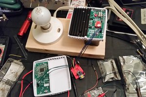
 Jared Young
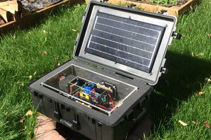
 oneohm