land-boards.com
-
I2C Front Panel Control
07/07/2021 at 20:22 • 0 commentsThere are several other IOP16 demos that use the Land Boards Front Panel I2C card. The Hackaday page for the Front Panel is here.
The code controls the four MCP23016 parts. These are 16-bit I2C parallel I/O expanders. The advantage using the Land Boards Front panel card is it only uses 2 FPGA I/O pins to read 32 pushbuttons and write 32 LEDs. The IOP16 runs the Front Panel I2C interface. The GitHub for the Front Panel example is here.
There are three examples so far.
- FrontPanel01 - Controls the second port of a Dual Port SRAM simulating control of a VHDL Retro Computer
- FrontPanel01B - Controls the second port of a Dual Port SRAM simulating control of a VHDL Retro Computer
- FrontPanel01_Test_LoopBack - Loopback toggle of pushbutton to LEDs.
There's also an example for Multicomp which controls an M6800 CPU running MIKBUG. This is a fully functional Front Panel example.
-
Blinkenlight Demo
07/07/2021 at 20:03 • 0 commentsNew Timer Unit
Added a timer unit to the IOP16. The timer unit allows a time value to be written to the Timer and the timer can be polled from the IOP16 to determine when the time has elapsed.
The timer unit can count in uSecs (0-255), mSecs (0-255) or Seconds (0-255). Writing the appropriate time value to the timer unit starts the timer running. The timer status register indicates when the count is in progress (d0 = 1). This facilitates simple polling.
Here's the IOP16 code to blink an LED off and every second:
000    START    0x7800    IOW    #0x00    IO_00   WRITE TO LED
001             0x2001    LRI    Reg0     0X01    TIME 1 SEC
002             0x7006    IOW    Reg0     IO_06   STORE TO START TIMER
003    WAITDUN  0x6104    IOR    Reg1     IO_04   READ TIMER
004             0x8101    ARI    Reg1     0X01    CHECK BUSY
005             0xDFFE    BNZ    WAITDUN
006             0x7900    IOW    #0x01    IO_00   WRITE TO LED
007             0x2001    LRI    Reg0     0X01    TIME 1 SEC
008             0x7006    IOW    Reg0     IO_06   STORE TO START TIMER
009    WAITD2   0x6104    IOR    Reg1     IO_04   READ TIMER
00a             0x8101    ARI    Reg1     0X01    CHECK BUSY
00b             0xDFFE    BNZ    WAITD2
00c             0xE000    JMP    START
-
New GitHub repo
07/06/2021 at 01:09 • 0 comments -
Speeding Up the CPU
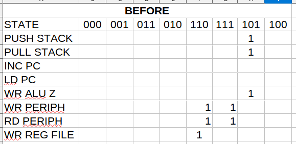
07/03/2021 at 21:17 • 0 commentsThe IOP16 runs at 8 of 50 MHz clocks per instruction. That is 6.25 MIPS which really is way more than fast enough for this use. The states are Grey Coded as follows:
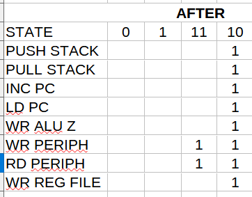
Most of the cycles do nothing. There is no good reason this can't run twice as fast. The Grey Codes are:
Made the change and it worked. It now runs at 12.5 MIPS. Way overkill, but why not.
-
Simple Application Example
06/22/2021 at 21:42 • 0 commentsSimple code example where the IOP16B reads the pushbutton and writes to the LED on the FPGA card.
Sources
- Application VHDL code is here.
- IOP16B VHDL code is here.
- Assembly code is here.
- Some other VHDL pieces are in subdirectories from here.
Memory Map
Single peripheral address (0x00), data bit (D0).
Top Level Entity
entity TestIOP16B is
  port (
    -- Clock and reset
    i_clk      : in std_logic := '1';   -- Clock (50 MHz)
    i_n_reset  : in std_logic := '1';
    -- The key and LED on the FPGA card
    i_key1      : in std_logic := '1';  -- KEY1 on the FPGA card
    o_UsrLed    : out std_logic := '1'  -- USR LED on the FPGA card
  );
end TestIOP16B;
CPU Instance
IOP16: ENTITY work.IOP16
-- Need to pass down instruction RAM and stack sizes
  generic map     (
    INST_SRAM_SIZE_PASS  => 512,  -- Small code size since program is "simple"
    STACK_DEPTH_PASS     => 4     -- Single level subroutine (not nested)
  )
  PORT map (
    i_clk             => i_clk,
    i_resetN          => w_resetClean_n,
    -- Peripheral bus signals
    i_periphDataIn    => w_periphIn,
    o_periphWr        => w_periphWr,
    o_periphRd        => w_periphRd,
    o_periphDataOut   => w_periphOut,
    o_periphAdr       => w_periphAdr
  );
Code
List file is:
000    SELF    0x6000    IOR    0x00    IO_00    read pushbutton
001            0x7000    IOW    0x00    IO_00    write LED
002            0xE000    JMP    SELF
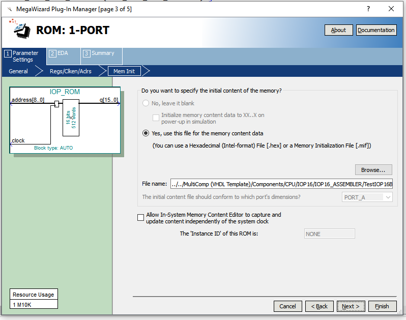
IOP_ROM
The ROM file name has to be IOP_ROM and it gets stored in the current project folder. That allows for the IOP16B to be used in other projects. The Assembler creates a MIF file which gas to be loaded:
IOP_ROM
The IOP_ROM instance has two parameters: INST_SRAM_SIZE_PASS and STACK_DEPTH_PASS.
-- Set stack size in STACK_DEPTH generic
IOP16: ENTITY work.IOP16
-- Need to pass down instruction RAM and stack sizes
  generic map {
    INST_SRAM_SIZE_PASS => 512,  -- Small code size since program is "simple"
    STACK_DEPTH_PASS    => 1     -- Single level subroutine (not nested)
)
INST_SRAM_SIZE_PASS has to match the size of the IOP_ROM.
STACK_DEPTH_PASS can be 0, 1, or > 1 (typically 4 for 16) deep stack,
Application Example Logic
-- Peripheral bus read mux

w_periphIn <= "0000000"&i_key1 when (w_periphAdr=x"00") else
              x"00";

-- Strobes/Selects
w_wrLED <= '1' when ((w_periphAdr=x"00") and (w_periphWr = '1')) else '0';

latchLED: PROCESS (i_clk)
BEGIN
  IF rising_edge(i_clk) THEN
    if w_wrLED = '1' then
      o_UsrLed <= w_periphOut(0);
    END IF;
  END IF;
END PROCESS;