 kutluhan_aktar
First of all, to elicit assiduous gas measuring results, I chose to utilize these MQ series gas sensors by connecting them to the Arduino Nano:
- MQ-2
- MQ-3
- MQ-4
- MQ-6
- MQ-9
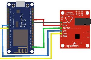
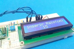
After choosing gas sensors for my device, I decided to control its settings and features with an IR remote control. Hence, I connected an IR remote receiver module to the Arduino Nano. Then, to display generated gas measurements, I used an ST7789 IPS screen.
Finally, I added a buzzer and a 5mm common anode RGB LED to get notified when gases reach dangerous levels.
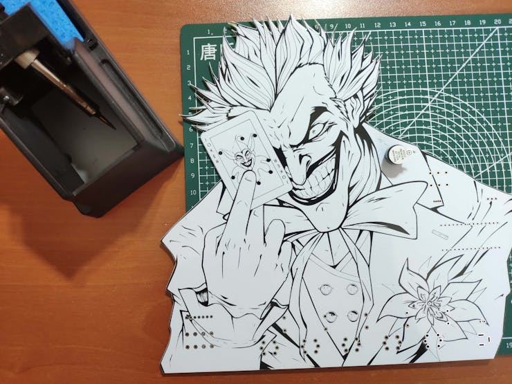
As you may have known, the toxic gas compound manufactured by Joker (Joker Venom or Laughing Gas) is considered remarkably dangerous in DC Universe. Hence, I shaped my device inspired by Joker's appearance in comics as a reminder of the detrimental effects of gases.
After completing wiring on a breadboard and testing the code, I designed my Joker-inspired PCB to complete my project. It became a stylish and intriguing addition to my workplace as an effective apparatus to monitor the presence of hazardous gases :)
Huge thanks to PCBWay for sponsoring this project.

Step 1: Designing and soldering the Joker Remote Gas Station PCB
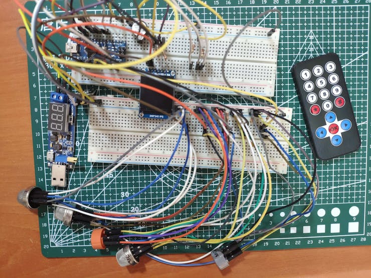
Before prototyping my PCB design, I tested all connections and wiring with the Arduino Nano on the breadboard.
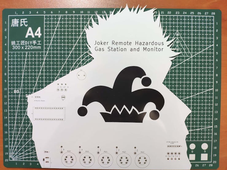
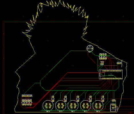
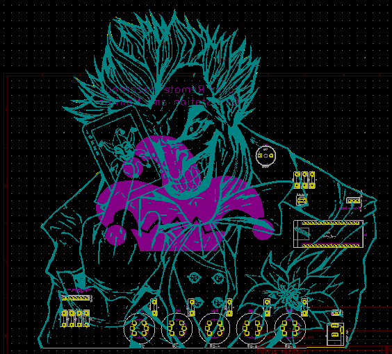
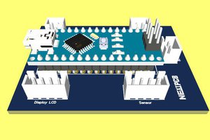
Then, I designed the Joker Remote Gas Station PCB by using KiCad. I attached the Gerber file of the PCB below, so if you want, you can order this PCB from PCBWay to create a fitting and apt apparatus to observe the presence of hazardous gases and get notified when they reach dangerous levels - inspired by malicious Joker :)
Click here to inspect and order this PCB directly on PCBWay.

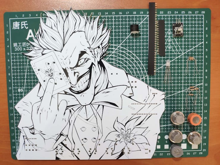
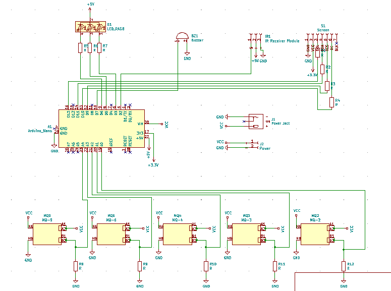
First of all, by utilizing a soldering iron, I attached Arduino Nano, IR receiver module, MQ-2 gas sensor, MQ-3 gas sensor, MQ-4 gas sensor, MQ-6 gas sensor, MQ-9 gas sensor, headers (female), buzzer, 5mm common anode RGB LED, 220Ω resistors, 20K resistors, and power jack.
Component list on the PCB:
A1 (Arduino Nano)
S1 (Headers for ST7789 IPS Screen)
IR1 (IR Receiver Module)
MQ2 (MQ-2 Gas Sensor)
MQ3 (MQ-3 Gas Sensor)
MQ4 (MQ-4 Gas Sensor)
MQ6 (MQ-6 Gas Sensor)
MQ9 (MQ-9 Gas Sensor)
BZ1 (Buzzer)
D1 (5mm Common Anode RGB LED)
R1, R2, R3, R4, R5, R6, R7 (220Ω Resistor)
R8, R9, R10, R11, R12 (20K Resistor)
J1 (Power Jack)
J2 (Headers for External Battery)

Step 2: Programming Arduino Nano and setting up components
Download the required library to be able to control the IR receiver module:
Arduino-IRremote | Library
Download the required libraries to be able to use the ST7789 240x240 IPS screen:
Arduino_ST7789_Fast | Library
Adafruit_GFX | Library
⭐ Include the required libraries.
⭐ Define the IR receiver module pin and settings.
#include <Adafruit_GFX.h>#include <Arduino_ST7789_Fast.h>#include <IRremote.h>// Define the IR receiver module pin and settings.#define RECV_PIN 2IRrecv irrecv(RECV_PIN); decode_results results;
⭐ By executing the IRrecvDemo.ino file in Examples, obtain the required IR codes from the IR remote control and define them.
#define up 0xFF18E7#define down 0xFF4AB5#define right 0xFF5AA5#define left 0xFF10EF#define ok 0xFF38C7
⭐ Define the ST7789 240x240 IPS display settings.
#define TFT_DC 10#define TFT_RST 9#define SCR_WD 240#define SCR_HT 240
⭐ To display images on the ST7789 screen, convert them to .c files by using this image converter below:
You can download the converted images I used in Downloads - gas.c, lethal.c, and toxic.c.
⭐ Include the converted images.
#include "gas.c"#include "lethal.c"#include "toxic.c"
⭐ Initiate the ST7789 240x240 IPS display.
Arduino_ST7789 tft = Arduino_ST7789(TFT_DC, TFT_RST);
⭐ Initiate the IR receiver module.
⭐ Start and clear the ST7789 240x240 IPS display.
irrecv.enableIRIn();...Read more »

 electronicsworkshops
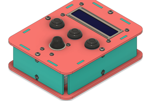
 Silícios Lab
Please feel free to leave a comment here if you have any questions or concerns regarding this project 😃