Close
0%
0%

Jacob's Ladder - Mini

A small, portable, battery powered Jacob's Ladder

Similar projects worth following
I always loved Jacob's Ladders when I was a kid. Once I saw the plans for a small version on the web, I knew I had to make one. The problem was the links to most of the parts no longer worked. So I bought equivalent parts from vendors in the USA. Initially I bought the most important part, the Boost Power Module from China. Since then, I was able to find them on Amazon (at 5 times the price). I highly recommend buying more than one (they're cheaply made).
There wasn't enough info (in the original plans) to figure out what size jar to use. I printed it out but, couldn't find a jar that fit. So I created my own 3D design.
All the design files are in GitHub at
https://github.com/ggrummer/JacobsLadder
I have to give credit to the original post that I based my design after. It's from BitLuni at https://www.youtube.com/watch?v=0Dp51Z-iPF4
There's also a good follow up with technical info from Heinz Behling at
https://makezine.com/projects/mini-j

High voltages, like the one in this design are dangerous.  It is unsafe for children or users of pacemakers or similar implants.

As noted, the Boost Power Module is the key to the design.  It produces a 20,000 volt output from a 3.6 to 6 volt input.  While experimenting with how far I can push one, I did manage to overheat it and cause it to internally short out.  Luckily, I bought 2 of them.  Now I only run the Jacob's Ladder for 10 seconds at a time.

There’s a lot of wire types that can be used for the ladder.  I’ve seen the following suggested: stainless steel, zinc-coated steel wire and silver-coated copper wire.  The goal is to use something that will resist corrosion (due to heat) while conducting the electricity.  I recommend using inexpensive gold-filled wire.  It meets all the requirements, looks cool, easy to work with and one only needs to buy 1 ft (30 cm) of it.  Cut in half & trim as needed.

Rechargeable LiFePO4 batteries are required due to their high current output and low voltage (as compared to the more common lithium-ion battery (3.2V vs 3.7V)).  The original design suggested using AA size batteries.  I thought having AA batteries around with different voltages was a bad idea, so I used a larger size.

The bottom case has extrusions which hold the components in place.  Mounting the battery holder is easy because it just plugs into the top 3D printed case.  

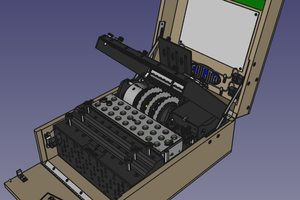
In case you’re wondering why I used a 4-position terminal block, you’re not alone.  A 3-position would have been fine, but I already designed the case for the 4-position.  The conductor in the second position was removed (which took some work).  I wanted to make sure the spark wouldn’t cross over to it (even though I doubt it would).  See the picture of the inside of the case.

The push button switch is easy to mount because the 3D printed case holds the nut in place.  The lock washer that comes with the switch is not used. 

 The jar is a common jelly type jar with a thin depth lid.  It’s only about 0.4” (12 mm) deep with 4 internal prongs (used to grab the jar) spaced 90⁰ from one another.  If the lid has visible threads, it’s on the wrong type of jar. 

An optional small magnet (any type) can be used to help the spark climb the ladder.  The south side should face up.

MiniJacobsLadder.mp4

Here's a short video showing the Mini Jacob's Ladder in action.

MPEG-4 Video - 7.72 MB - 07/27/2021 at 20:25

Download

JacobLadderPL.xlsx

List of parts used in my version of the Mini Jacob's Ladder. The most up to date version is in GitHub. Use this file to give you an idea of what involved in making this.

sheet - 10.94 kB - 07/27/2021 at 20:20

Download

JLCaseTop2.stl

3D printer file for the top part of the case.

Standard Tesselated Geometry - 385.53 kB - 07/30/2021 at 13:47

Download

JLCaseBottom2.stl

3D printer file for the bottom part of the case.

Standard Tesselated Geometry - 26.45 kB - 07/30/2021 at 13:48

Download

View all 8 components

  • 1
    Assembly notes

    Before inserting the battery holder into the case, there's one thing you'll need to do.  The battery holder is polarized, one corner has a little nub.  That nub has an associated hole in the case, closest to the switch.  A wire must be soldered to the plus and minus solder lugs, on the short side of the battery holder, on the side opposite the short side with the nub. 

    Note the battery holder has polarity markings on it.

View all instructions

Enjoy this project?

Share

Discussions

Similar Projects

Does this project spark your interest?

Become a member to follow this project and never miss any updates