Close
0%
0%

TOSLINK DAC

Instead of a $10 box from Amazon, go above and beyond

Similar projects worth following
Starting from
$70.00
nsayer has 2369 orders / 163reviews
Ships from United States of America
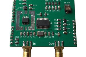
You can get the equivalent of this for $10 from Amazon - it's an optical digital audio to analog audio conversion box. But the typical cheap units don't really tell you anything about how good they are. Instead of settling for that, this project aims to bring quality parts and modern design to bear.

This came about because I bought a box from Belkin to do AirPlay 2 for our patio speakers (which have an amplifier I built myself). That Belkin box's analog audio output is about 20 dB too low, but fortunately they include a TOSLINK output jack. Buying the aforementioned $10 box from Amazon solved my problem, but I kinda wanted to know how to build the equivalent, and having done so, try to do better.

The current design comes down to three separate subsections.

First is a TOSLINK receiver module. This is a little plastic thing that takes in 5 volt power and outputs a TTL level stream matching the optical input. There isn't a whole lot to say about this. It's self-contained and just needs a single bypass cap and series inductor for the supply pin. The optical signaling is biphase encoding. This makes for easy clock extraction. Between every clock period the signal changes state. If the input pulse train is the same bit level as the previous bit, then nothing else happens. If it's different, then at the 180º mark there is a second state change. So for an input clock frequency of 1 MHz (just an example), a series of either 00000... or 111111.... is represented by a 1 MHz square wave. A series of 01010101.... is represented by a 2 MHz square wave.

The next section is the digital data stream receiver. For this, I've gone through four different choices. The first iteration used the STA120. That worked, but it only comes as a SOIC28, which is rather large, and seemed to be heading towards obsolescence (did I mention that this whole project is at least 10 years out of fashion?). Replacing that was the DIR9001, which was a good choice, but like the STA120 was limited to 96 kHz sample rates. To go higher, I needed to find a better chip that was still capable of being configured purely with hardware strapping. The best choice I could find was the CS8416. It can go up to 200 kHz sample rates and can be strapped with 8 47 kΩ pull-up-or-down resistors. The CS8416 can take care of any pre-emphasis correction for us, allowing us to just strap the DAC for no pre-emphasis. In all 3 cases, the output was configured for i2s, with the receiver being the master and a master clock of 256x the L/R clock. The problem with the CS8416 is that without any input, it clocks the output at around 750 kHz, which is the minimum VCO clock for the PLL. Sending that slow a clock into the PCM1793 results in a low level hiss on the output even though MUTE is asserted by the error output. This prompted me to try the WM8804. That took care of the hiss, though it does require adding a 12 MHz crystal to the BOM. The other downside is that in hardware mode, there's no support for reporting or handling deemphasis, but so far I've not encountered a source that used it.

The original DAC was a CS4334. It takes i2s input. This consists of the master clock (SCK), bit clock (BCK), L/!R (LRCK), and DATA. Instead of the BCK signal, you can send a de-emphasis selection signal from the STA120, but when I attempted this with a prototype the audio sounded noisy. It would seem that when you don't send SCLK, the CS4334 makes assumptions about the relationship between SCK and the frequency of LRCK to derive an internal bit clock. This seems to not work for the output format of the STA120. That, and the !DEM signal was always high, which implies that emphasis on the digital signal is never used, so there's no harm in not supplying that signal to the DAC.

Along the way I decided to attempt to design something a bit better. This started with the PCM1793 192 kHz 24 bit DAC. That DAC has fairly impressive THD and S:N specs, and requires an external differential to single-ended converter and LPF. That uses the OPA2134 dual op amp, which is also an impressive part in and of itself. As before, the output DATA, BCK, LRCK and SCK (configured at the receiver for 256xFs) are fed directly. In addition, I decided to connect the ERR output of the decoder...

Read more »

TOSLINK_DAC_v1_5.pdf

Adobe Portable Document Format - 84.23 kB - 11/04/2021 at 20:22

Preview

TOSLINK_DAC_v1_5.sch

sch - 340.32 kB - 11/04/2021 at 20:22

Download

TOSLINK_DAC_v1_5.brd

brd - 117.03 kB - 11/04/2021 at 20:22

Download

TOSLINK_DAC_v1_4_1.pdf

Adobe Portable Document Format - 91.85 kB - 10/22/2021 at 02:50

Preview

TOSLINK_DAC_v1_4_1.sch

sch - 332.17 kB - 10/22/2021 at 02:49

Download

View all 12 files

  • 1.5 build report

    Nick Sayer11/04/2021 at 19:27 0 comments

    The WM8804 decoder looks like a winner. The audio sounds just as good as before (which is hardly a surprise), but when muted there’s no hiss anymore.

    Not only that, but the 8804 seems to be a chip very much in demand today - it’s one of the favorites for adding on to a Raspberry Pi.

    So unless there are anymore surprises, I think this may be a final design.

    If there’s a possible complaint it’s that the output levels may be just a tad hot. A 1 kHz 0dBFS sine wave winds up being about 6v P-P. Correct line level would probably be closer to what the CS4334 produced - about 4V (keep in mind we’re talking about an absolute peak level here).

    For me, I’m satisfied to simply turn down the volume on the amp a little bit. I really don’t want to attempt to reengineer the analog out stage. If I were forced to reduce the levels, I’d probably just add an output pad. But I don’t think I will.  

  • Another chip to try

    Nick Sayer10/24/2021 at 05:00 0 comments

    At this point, I'm pretty much sold on the DAC/analog sections of the design. While it's undoubtedly possible to do better, I'm satisfied with the performance. I'm still a little bit put out by the idle noise, so I am going to try another receiver chip to see if it helps. The new nominee is the WM8804. It's an SSOP-20 package instead of QFN, which is easier to deal with. One big difference is that this chip requires a 12 MHz crystal. Hopefully on PLL unlock it can supply either no clock or a sufficiently fast clock that the DAC won't be noisy.

  • v1.4.1

    Nick Sayer10/22/2021 at 02:47 0 comments

    v1.4.1 is back from OSHPark. It's almost perfect, so far as I can tell. There's just one interesting issue. If you remove the optical input, you get a noticeable white noise output. This is despite the MUTE pin being pulled high by the ERR output of the CS8416. This didn't happen with the DIR9001.

    Now, when the PLL unlocks, the master clock output is 750 kHz, which results in something like a 2 kHz LRCK, which is far lower than the minimum input to the PCM1793. But damnit, MUTE is pulled high, so none of that should matter. ERR is driving both the error LED and MUTE, and as a result, it's a little bit low - about 2.8 volts or so. But the PCM1793's minimum threshold for high is 2 volts, so it still should be enough.

    I guess a workaround for this would be to supply an actual replacement clock to OMCK. In hardware mode, the CS8416 will supply OMCK on RMCK (and will derive BCK and LRCK from it) if it's available. If not, then you get the unlocked PLL clock of 750 kHz.

    I don't think I'll bother, though. If I were to do anything more at this point, I might attempt to replace the CS8416 with an alternative, but I don't think I have a great deal of incentive to do so since the PCM1793 itself isn't rated for higher than 200 kHz sample rates, and I certainly have no use for anything higher than that.

  • v1.4

    Nick Sayer10/11/2021 at 23:06 0 comments

    I got v1.4 boards back from OSHPark. This is the version with the CS8146 in a QFN footprint. At first the prototype didn't work, but swapping out one of the PLL filter caps fixed it. I must have picked up the wrong one assembling it. This version also has dual RCA jacks for output. They take up most of the front panel, but they should be much more durable. And, no, I didn't buy gold-plated jacks.

    The CS8146 version functions exactly like the DIR9001 version, but has a maximum sample rate of 192 kHz instead of 96 kHz. I suspect that is the maximum sample rate you can expect from TOSLINK. At 192 kHz sample rate, the bit clock is over 12 MHz, and S/PDIF has extra framing, so its data rate is even higher. 

    The one thing I am not sure about is whether or not the CS8416 needs a reset circuit. The PCM1793 datasheet pretty strongly implies that it has a power-up reset circuit, but the 8416 sheet says that you have to hold !RST low until all power supplies and voltages are stabilized. I'm going to add a footprint for a MIC803 supervisor chip. It will hold RESET low during power-up and then for a few ms after the 3.3 rail is over 3.0 volts. Along with that, a pull-up on !RST. If nothing else, that will give us a more convenient spot to force !RST low if it's ever necessary.

  • Measurements

    Nick Sayer09/29/2021 at 07:34 0 comments

    I took some measurements rather than go to bed on time.

    I'm not happy with them, but I am not sure whether it's my measurement technique or the equipment or the device under test.

    I sort of have the feeling that the device isn't to blame. If I lift the probe off the output pin, I don't see the noise floor change any, so that tells me that I'm not seeing the device create extra noise on its output.

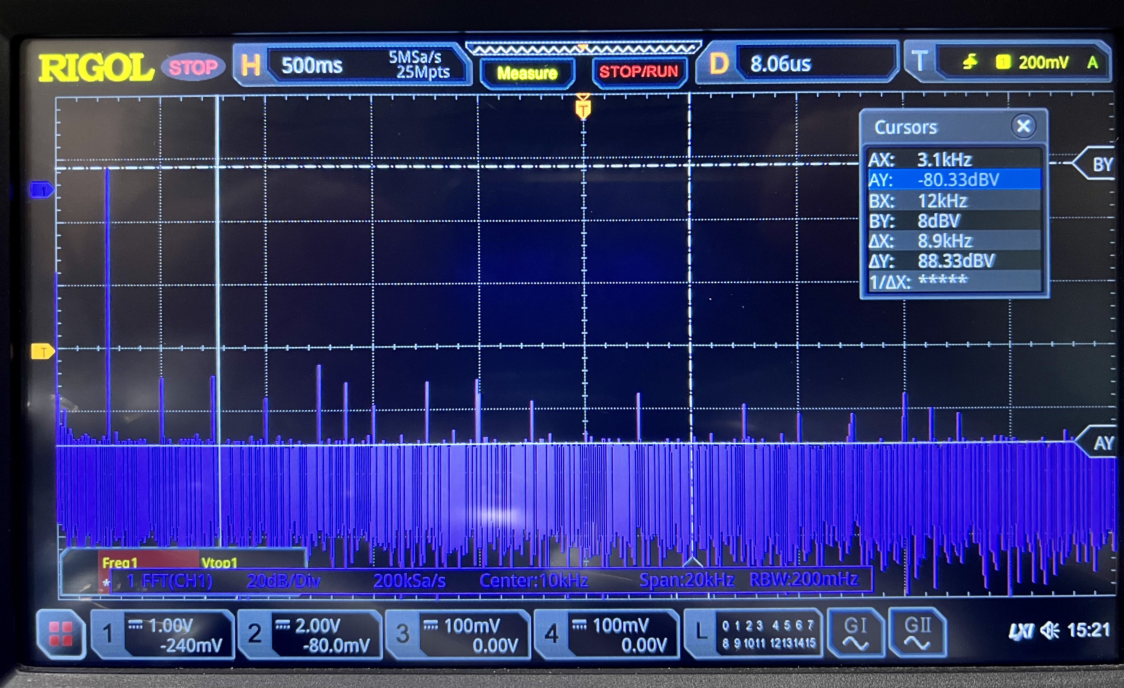
    This screenshot is an FFT with my mac playing a 1 kHz sine wave at full amplitude (I hope) through the AirPlay device I have and into the DAC. AY is at the noise floor and BY is at the peak of the fundamental. The delta between the two is just shy of 90 dB. The specs claim that on a good day this DAC should be able to do 113 dB. But as I said, I don't see the noise floor drop when I take the probe off the output, so maybe the noise floor of the scope is higher than the noise floor of the DAC. Either that, or perhaps the 1 kHz fundamental peak is lower than it is in reality (that seems unlikely).

    That said, figure 19 on the PCM1793 datasheet shows a noise floor at -140 dB and a signal peak at -60 dB. That's a difference of... 80 dB, so maybe this is measuring correctly? I'm not that experienced with this sort of measurement, so I can't really be sure. Anyone want to comment?

  • Build report

    Nick Sayer09/29/2021 at 06:05 0 comments

    Version 1.1.1 came back from the fab, and electrically it works perfectly. Mechanically, there are still some issues.

    The biggest one is that the TRS jack just doesn't stick out far enough. Attempting to plug into it doesn't go in far enough before it hits the front panel, so it makes poor contact.

    I've decided to bite the bullet and go with dual RCA jacks instead. Surely those will stick out far enough. While I'm at it, I decided to move the TOSLINK jack just a bit further back. Mating hasn't been an issue thus far, but I want to make it even less of a potential one. I might wind up deciding to go with OSHpark's half-thickness boards for the front and back panels as well. We'll see.

    The two RCA jacks and the "error" LED barely fit on the front panel of the chassis I sourced, but I am fairly confident that fit they will.

    The sounds is just as beautiful as it was before. I'm going to have to find a way to generate some optical test signals and try to measure the S:N of the prototype to see if all of my noise reduction precautions have been sufficient. The plan is to attempt to generate sine tones and look at the output with the FFT mode of my scope to look for spurs and measure the S:N.

  • Going further

    Nick Sayer09/19/2021 at 17:22 0 comments

    The boards for the DIR9001 + PCM1793 aren't back yet, but the DIR9001 only going to 96 kHz only allows for half of the DAC's sample rate range to be used. Swapping the DIR9001 out for the CS8416 would fix that. They're backordered until the next ice age, but I have thrown together a design that puts the 8416 in hardware mode and configures it how I think it ought to work for the 1793.

    Meanwhile, I have every confidence that the boards that arrive this week will work. I also have some confidence that I can put this on Tindie at $50 (board only) and in comparison to other products on Amazon that are using these same chips, I think the pricing may not be completely out of line.

    EDIT: It bugged me a little that the oscillator frequency of the MAX1721 is about 125 kHz. For the 96 kHz variant, that doesn't bother me too much, but I really want the charge pump to run faster than the maximum sample rate for the board. I've discovered the SP6661, which runs at just under a megahertz, so that's going to be the device for the CS4816 variant.

  • More tests

    Nick Sayer09/15/2021 at 19:10 0 comments

    I hacked together a charge pump on a little SOT23 breakout board and wired that into the prototype. It sounds really good. I certainly can’t hear any artifacts from the charge pump in the audio. And the chip I used had quite a low oscillation frequency. I want to use the MAX1721 in the final design so that hopefully the switching frequency will be too high to impact the audio.

    I tested with my AirPods Max so as to try to maximize my ability to pick up any noise or distortion, but didn’t hear anything untoward. That’s not a great test, of course, but it’s a start.

    I also tested against the other two TOSLINK DACs I have handy - a $10 one from Amazon and the one built with the CS4334. The other two sound distinctly flat to me by comparison. I am not sure if it’s a placebo effect or not (and I’m not sure I would be able to by definition), but the more expensive DAC does seem to make a difference.  

  • Next prototype built, but there's a problem

    Nick Sayer09/13/2021 at 03:55 0 comments

    I built the next prototype. While the boards were being fabbed, I found an error in the schematic - for the left channel, the + and - differential outputs from the DAC were reversed. I cut the traces on the board and bodged them back.

    But the audio of the prototype sounded bad. After spending the afternoon trying to figure it out, it turns out that the problem was that I gave the final amplifier a unipolar power supply (that is, the V- pin of the amp was grounded.

    Lifting that pin and temporarily hacking in a 5 volt wall wart with - to V- and + to ground gave correct audio (albeit with a nasty 60 Hz hum).

    The problem now is that everybody I've found on the Internet who has made the schematic of their DAC public has a bipolar power supply.

    Well, you can make -5 volts from +5 with a charge pump. The MAX1721 has a switching frequency of 125 kHz, so ostensibly above anything audible. Hacking in a MAX1720 on the prototype did make it work. But if it's possible, rebiasing the output amp to operate on a 2.5 volt offset, reducing the gain and adding a DC block on the output would probably be better for the THN spec of the result.

    The next prototype board (boards?) will test one or both of these options.

  • Even better

    Nick Sayer08/26/2021 at 02:09 0 comments

    I'm still not entirely sure this project is worth productizing or not. But if it is, there is probably room at the high end for something particularly good.

    In looking for interface chips, it appears that the DIR9001 is the best overall choice.

    For DACs... well, it's all over the place. The PCM1730E is an excellent choice... at $20 a piece.

    The PCM1793 is much more reasonably priced, at about $6.25 each. Couple that with an OPA2134UA at about the same price to be the output LPF and buffer... and we might have something worth actually trying to sell.

View all 15 project logs

Enjoy this project?

Share

Discussions

victor mccormicke wrote 08/04/2023 at 07:48 point

Your project aims to address the limitations of cheaper options by prioritizing the use of quality parts and modern design principles. By focusing on transparency and clear communication regarding specifications and performance, you intend to attract customers who value audio quality and are willing to invest in a premium product.

https://www.tellpopeyes.biz/

  Are you sure? yes | no

Evan wrote 02/27/2023 at 15:58 point

Hi Nick,

Great work as always, and I'm thinking about working on something similar with an integrated HPA.

Is there a reason why you didn't consider the ES9010K2M, which has native SP/DIF in, for the DAC? It seems a bit cheaper and more highly integrated than using a separate SP/DIF frontend: https://ismosys.com/ess-evaluation-boards/

The Wolfson/Cirrus frontends seem pretty expensive for something that doesn't include the DAC chip itself but I'm still building a complete understanding of the
problem space.


-Evan

  Are you sure? yes | no

Nick Sayer wrote 02/27/2023 at 19:05 point

The only issue with that chip is that it appears to me from a brief reading of the datasheet that you have to control it via i2c, so that means adding some sort of microcontroller and programming it. The chips I am using in the current design can be configured with hardware strapping and can run without any external intelligence.

  Are you sure? yes | no

Similar Projects

Does this project spark your interest?

Become a member to follow this project and never miss any updates