 Ratti3
-
1Known issues
Updated 02-Aug-2022:
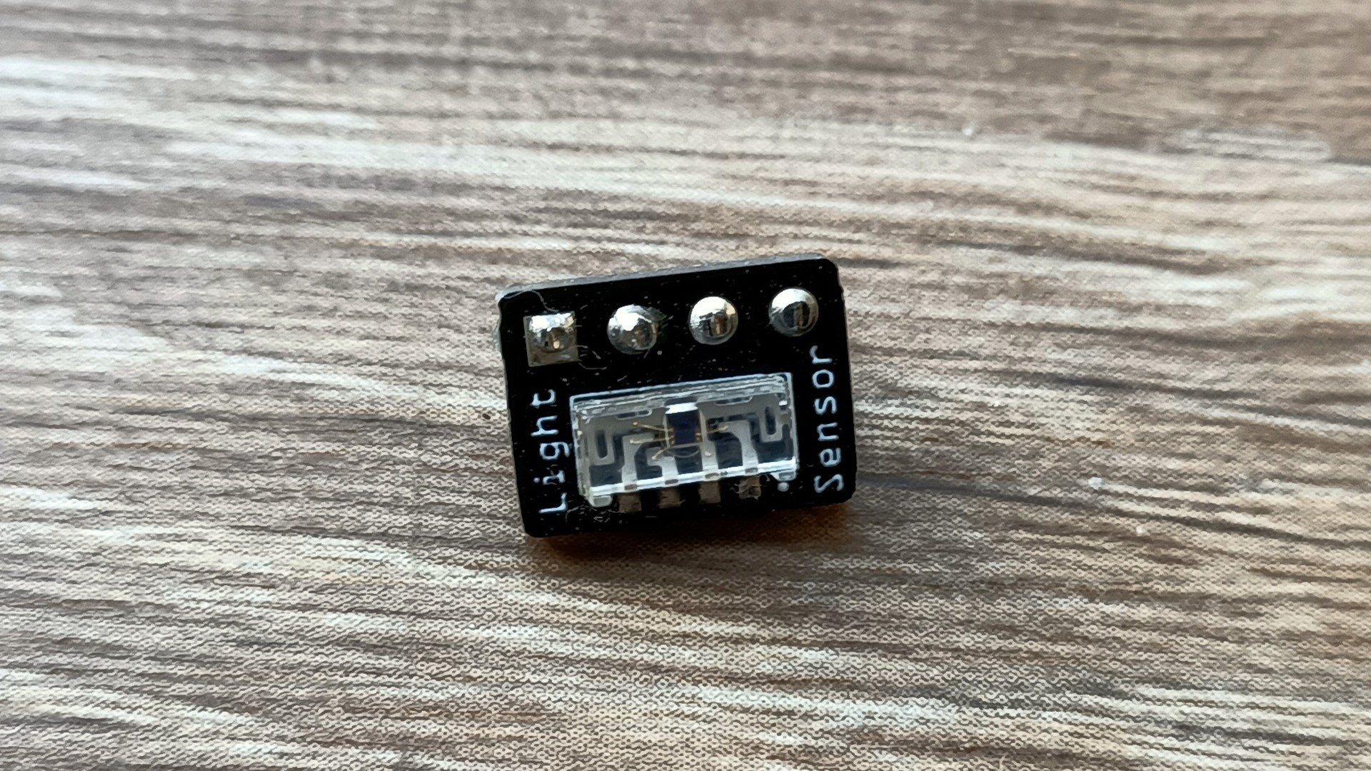
- On the IN-18 PCB, the VEML7700 light sensor can pick up the light from the Nixie, this can prevent the Nixies from turning off at night, the light level threshold can be adjusted accordingly to compensate for this or the sensor can be moved further back using 4 wires.
- The code is almost complete, I've not uploaded the latest version to GitHub yet, functions missing is the auto off based on the state of the sensors. Setting the time manually using the buttons I think it gets stuck on setting the year, I'll look into that. You can set the time fine using the WebUI.
- It is recommened to use twisted wire pair for connecting the BME280 otherwise the Arduino can crash.
-
2Tools required
I did have to buy several tools to make this clock, these include the following:
![]()
Belt & Disc Sander: https://www.vonhaus.com/vh_en/benchtop-belt-and-disc-sander
Bench Drill Press: https://www.amazon.co.uk/gp/product/B00766C1A8
Mini Bench Drill Press: https://www.amazon.co.uk/gp/product/B0012RQG94
Mini Belt Sander: https://www.amazon.co.uk/dp/B09YNPZ95T
Mini Table Saw: https://www.amazon.co.uk/gp/product/B07S3N9T7T/
Rotary Multi Tool: https://www.amazon.co.uk/dp/B01N9GVO2L
Forstner Drill Bits: https://www.amazon.co.uk/gp/product/B072XJ5NG3
Clamps: https://www.amazon.co.uk/gp/product/B001C7LTSW -
3PCBs
All the PCBs have been designed with SMD components where possible. Board to board connections are done with low profile headers. Please note the part number of these headers are different on the BOM, the EasyEDA schematic mentions the correct part. Power, switch and I2C device connecions are done using JST connectors.
The Arduino PCB headers for the Arduino Nano are only partial, this is so the board could be made as small as possible, only the requried pins on the Arduino are soldered to match the header pins.
Some of the PCBs have large copper areas, as a result you will need a decent sodering iron to maintain the temperature when soldering components.
Nixie pins are the type that you see all over Ebay and are usually sold from China.
PCBs and Schematics can be found on the EasyEDA project page:
https://oshwlab.com/ratti3
Direct links:
https://oshwlab.com/Ratti3/in-18-hv5530-nixie-clock-shield
https://oshwlab.com/Ratti3/in-12-hv5530-nixie-clock-shield
https://oshwlab.com/Ratti3/arduino-nano-33-iot-shield-for-nixie-clock
https://oshwlab.com/ratti3/nixie-clock-ucc3803-5v-to-170v-power-supply-r2
https://oshwlab.com/ratti3/nixie-clock-ucc3803-5v-to-170v-power-supply-r4
https://oshwlab.com/ratti3/nixie-clock-usb-c-dc-power-board-r3
https://oshwlab.com/ratti3/nixie-clock-veml7700-light-sensor
https://oshwlab.com/ratti3/nixie-clock-bs612-pir-sensor
https://oshwlab.com/ratti3/nixie-clock-led-colon![]()
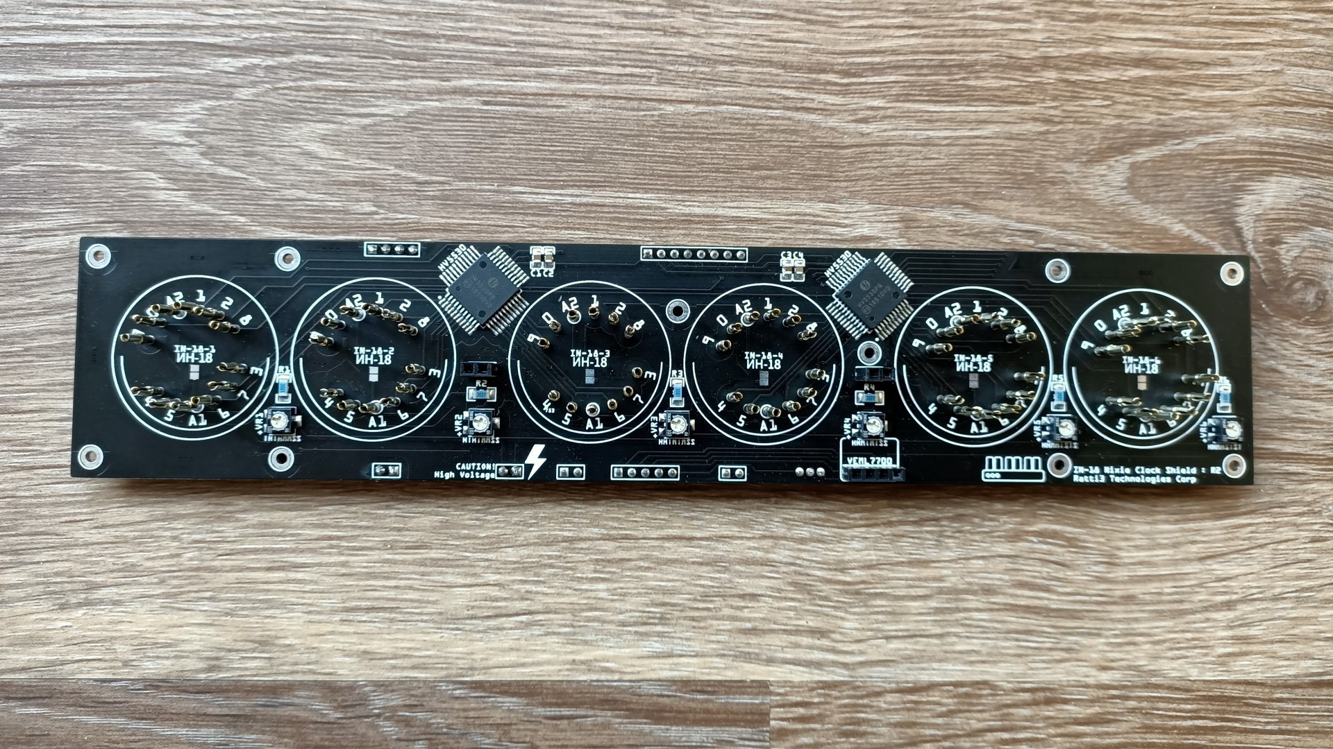
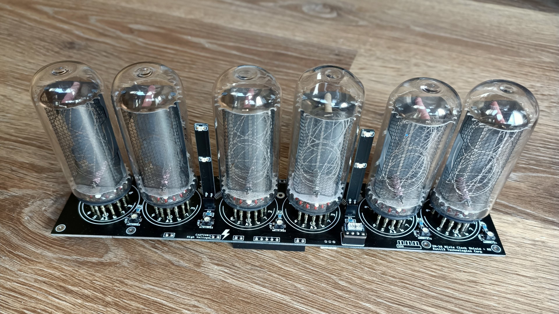
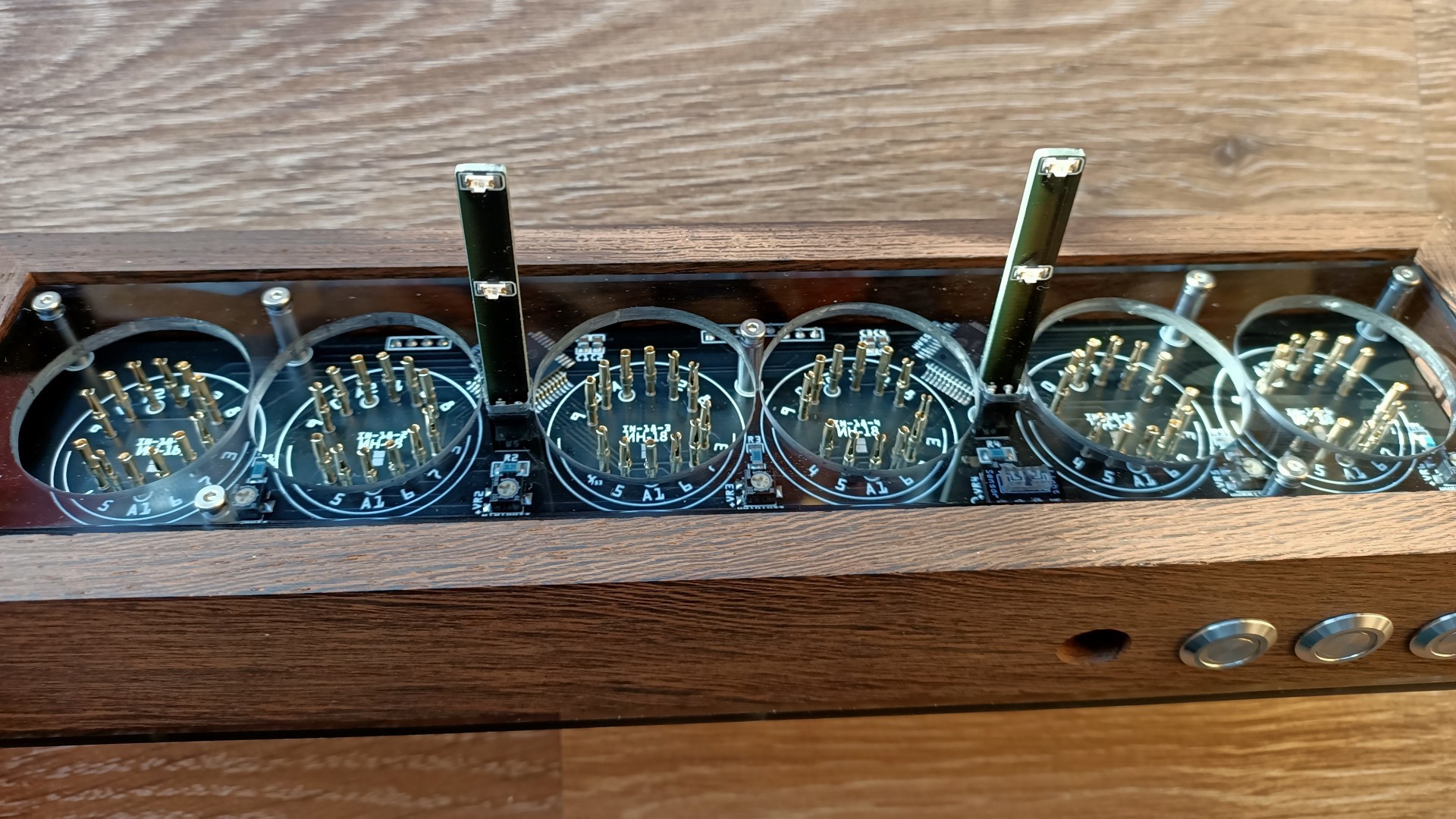
The main board that holds the Nixies ![]()
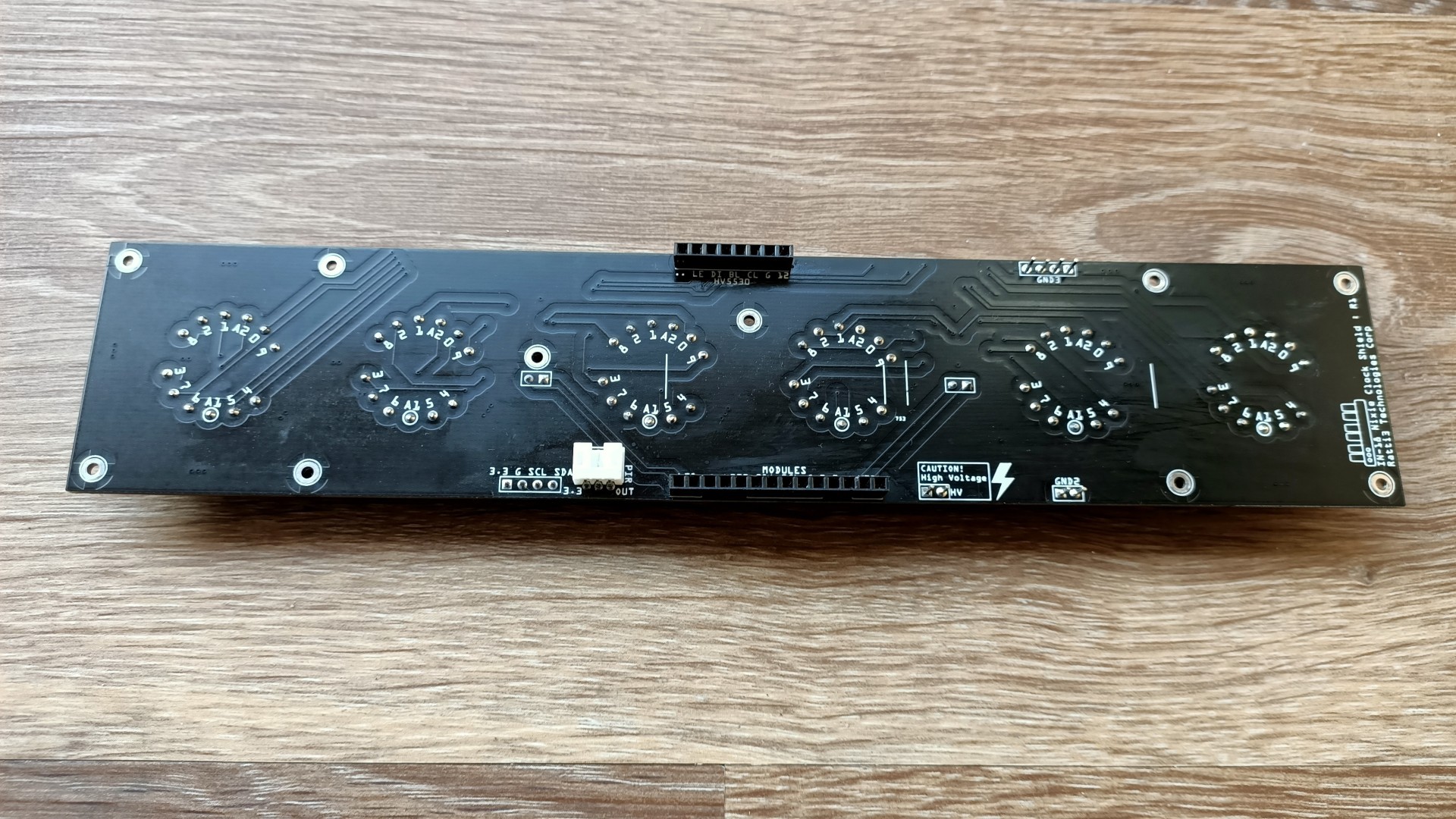
Underside of the main board ![]()
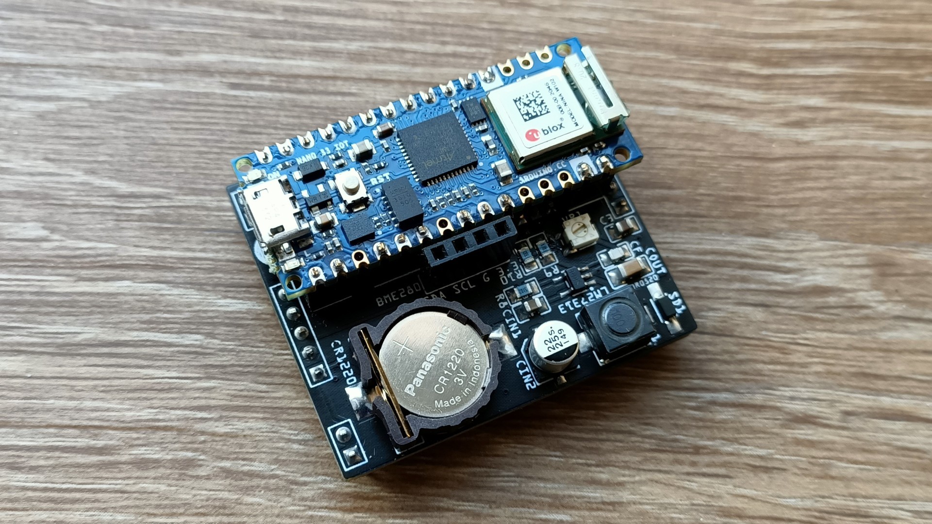
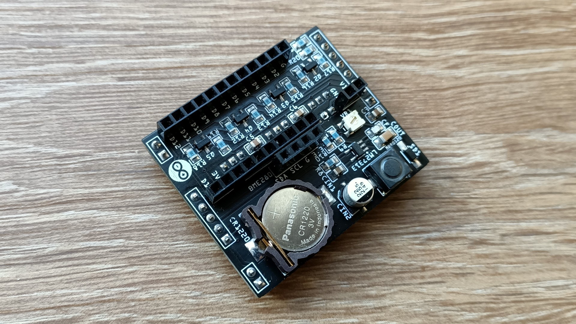
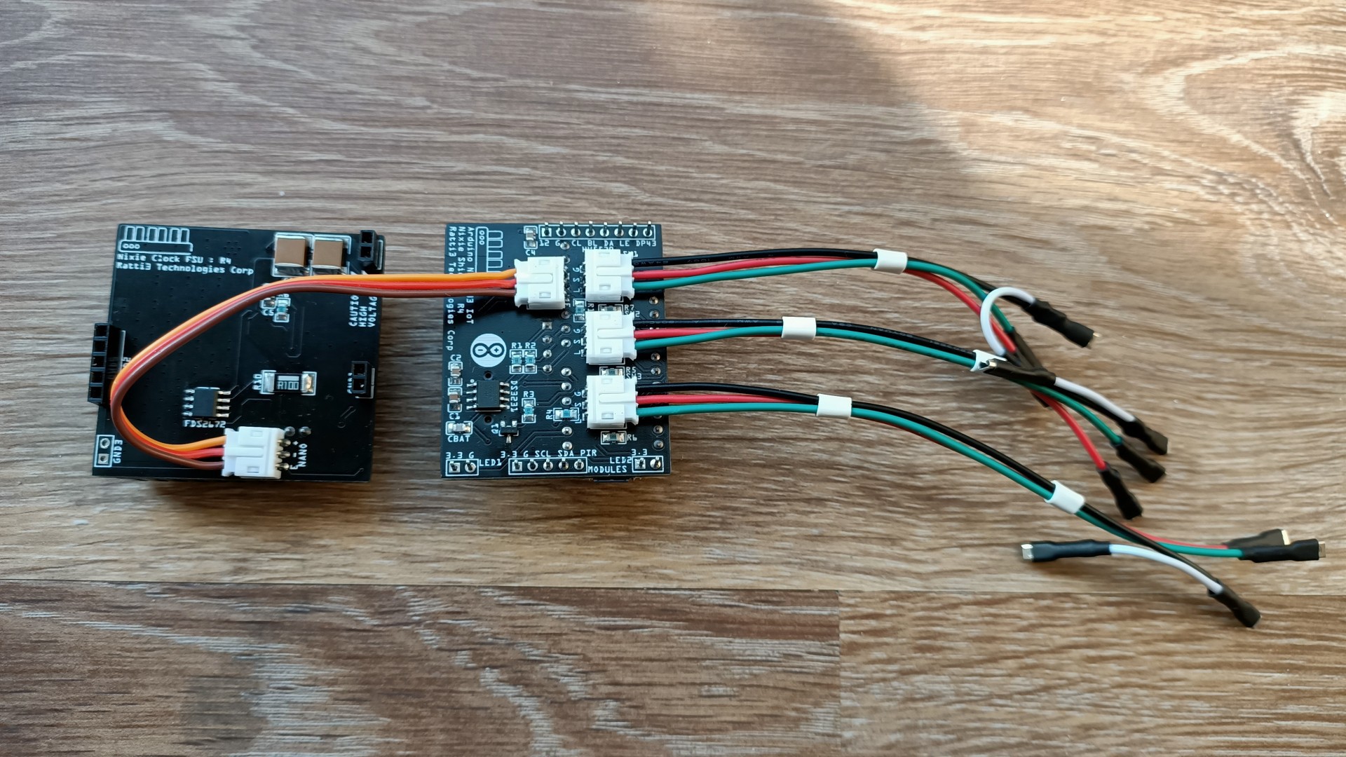
The Arduino/DS3231/12V board with the Arduino Nano 33 IoT mounted ![]()
Underside of the Arduino board, JST connectors for power and switches ![]()
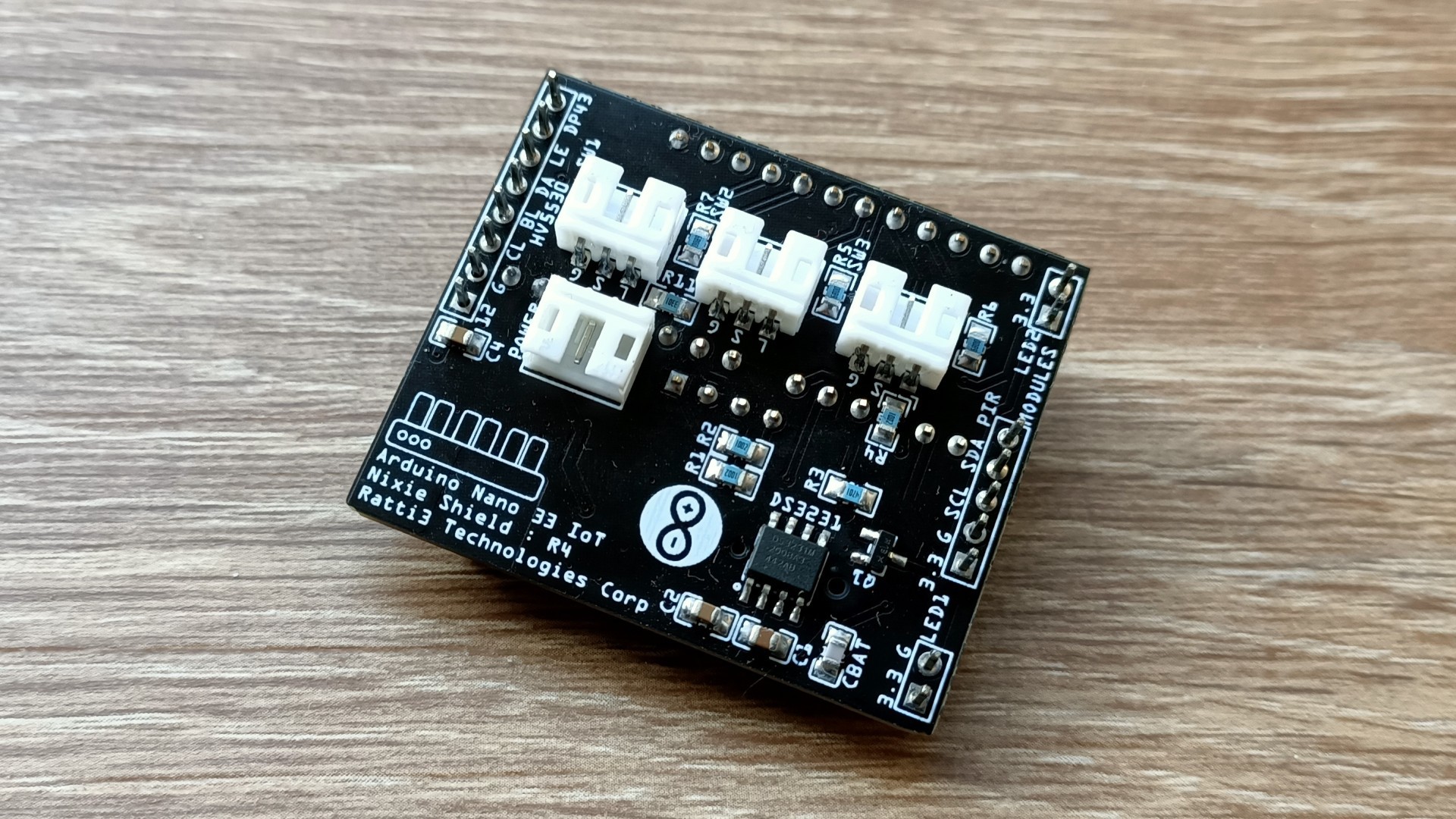
Arduino Board with the Arduino removed, note the gaps in the Arduino header pins ![]()
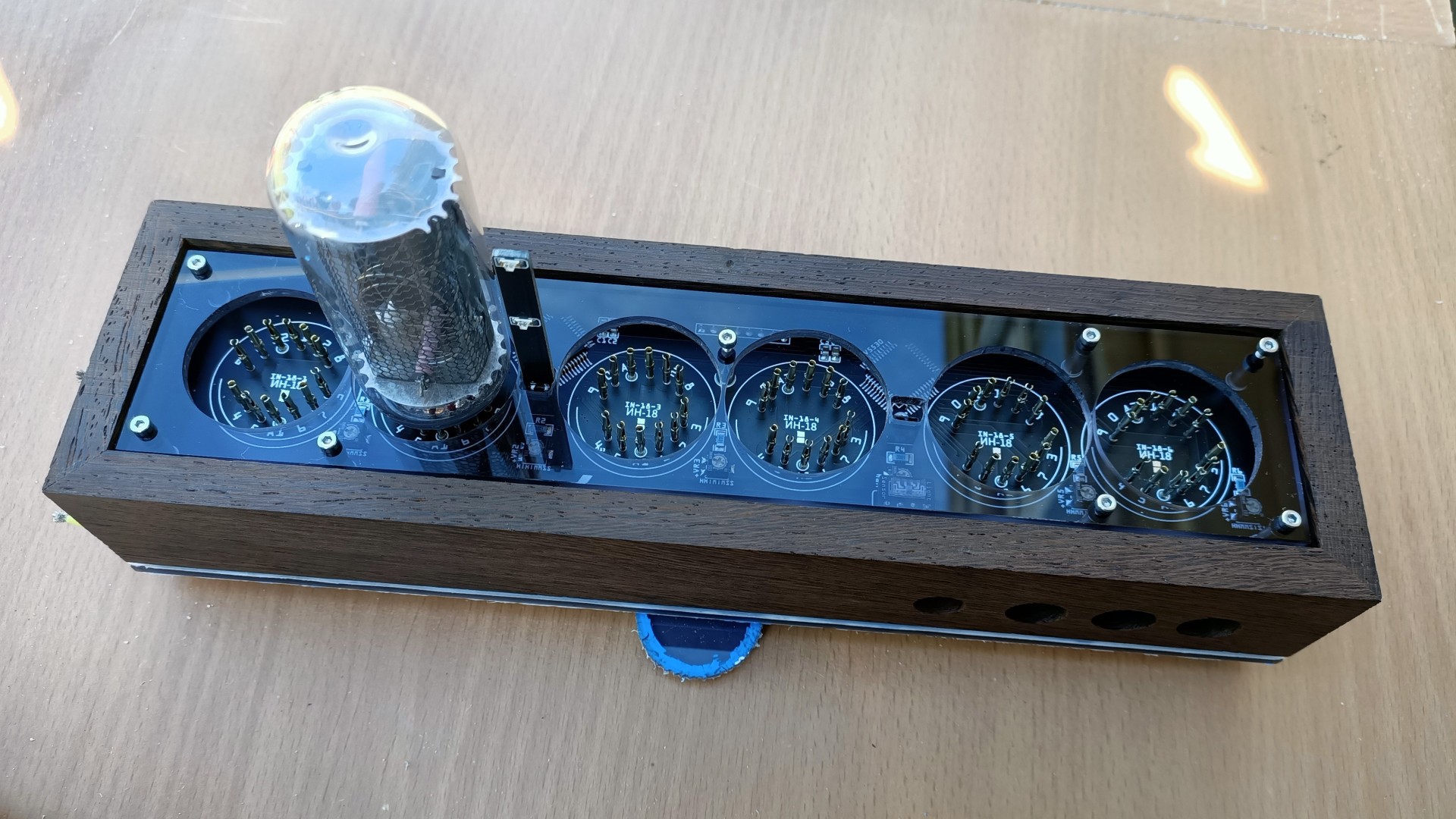
Nixies mounted on the main board, the VEML7700 sits between tube 4 and 5 ![]()
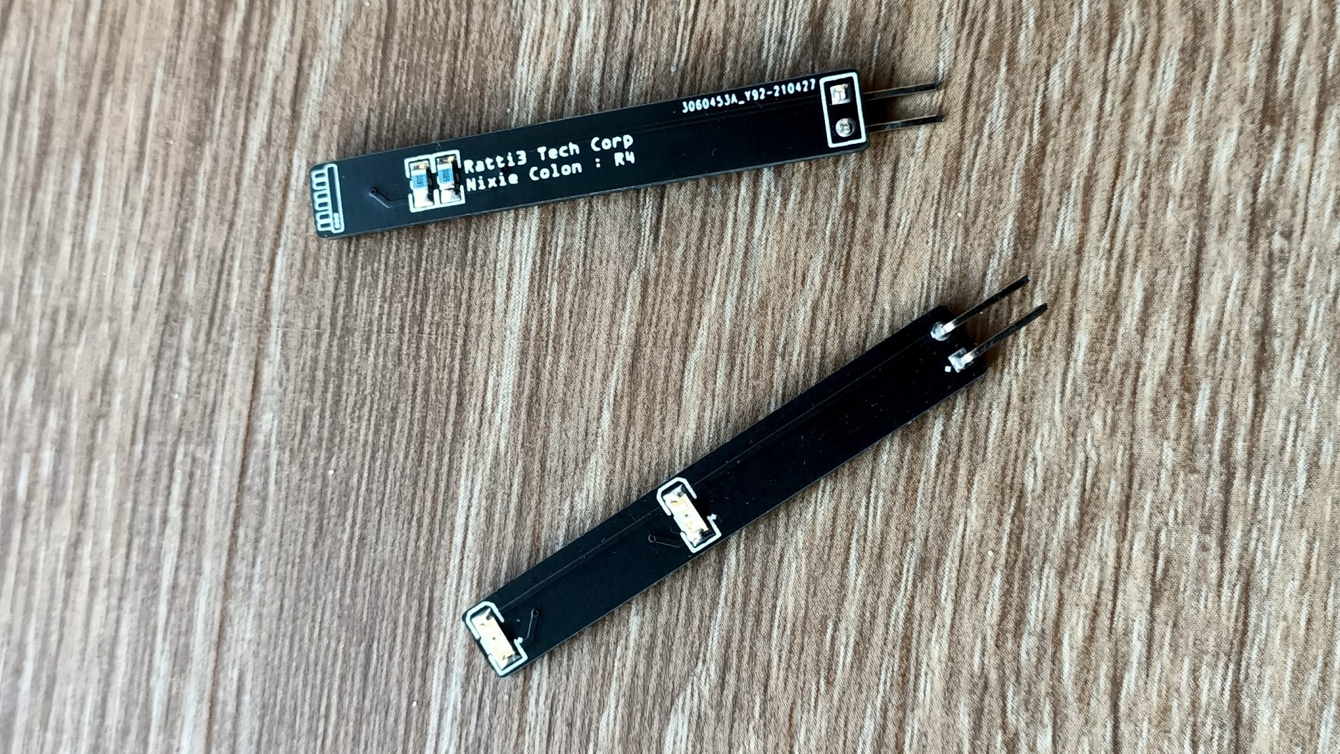
Colon board, these are orange LEDs that are similar colour to the Nixie ![]()
VEML7700 I2C Light Sensor Board ![]()
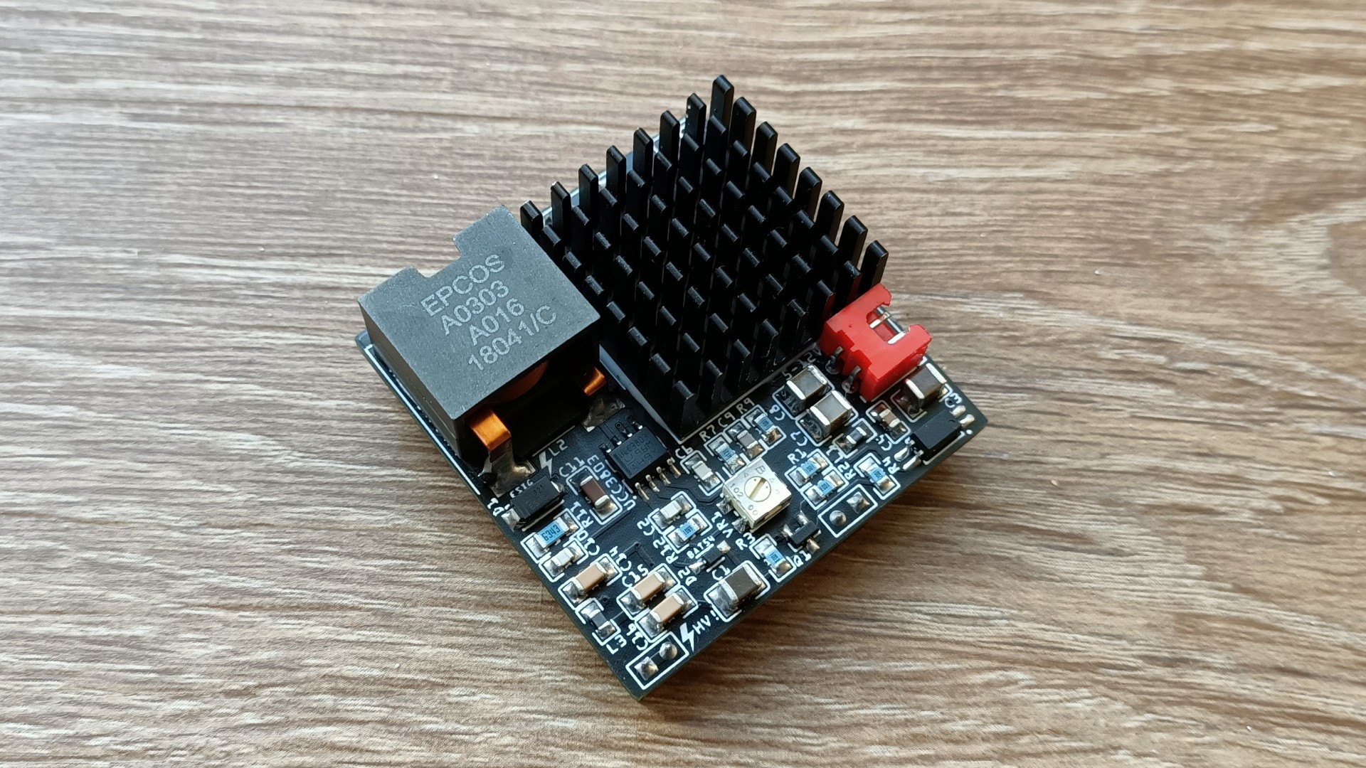
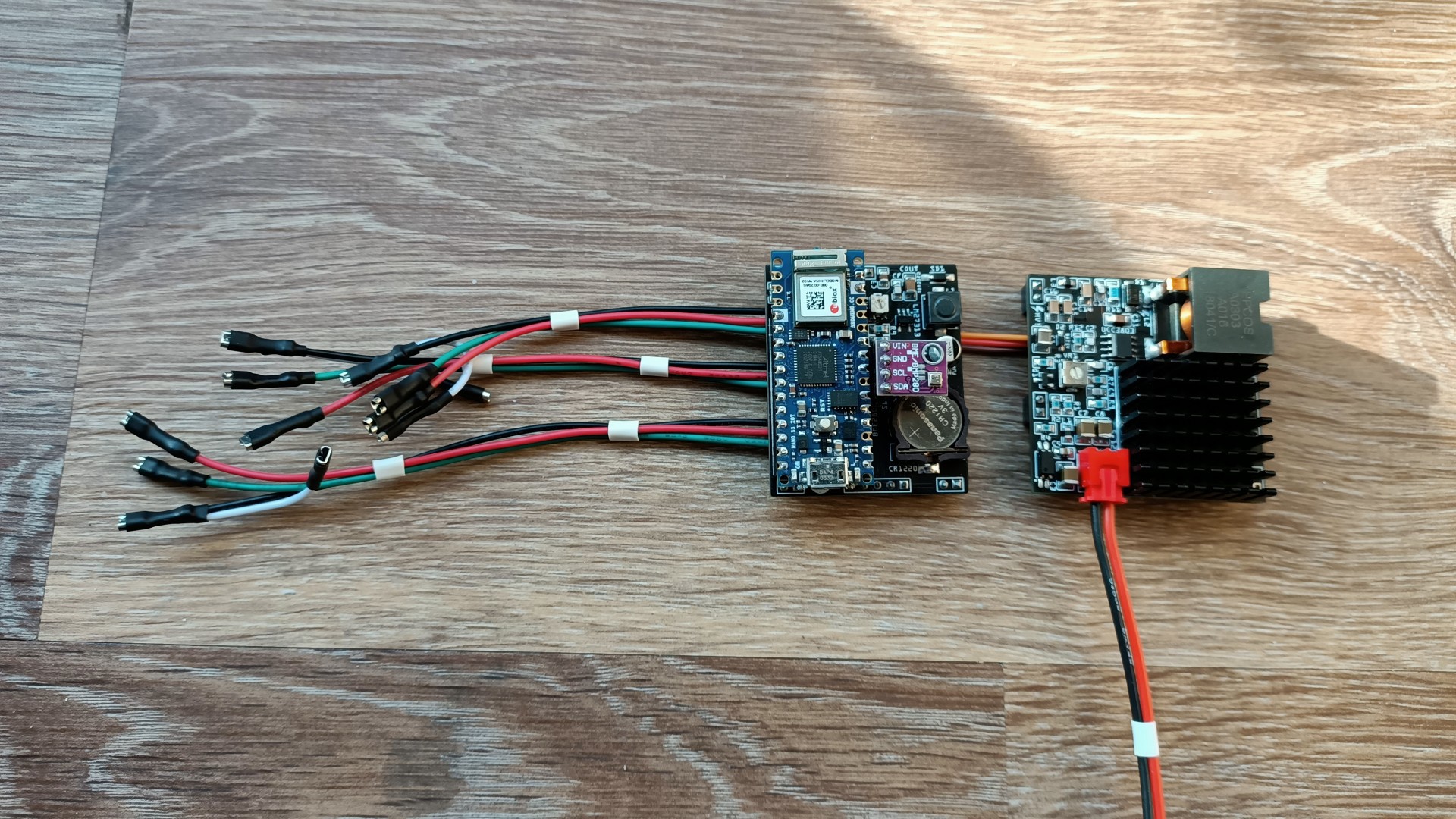
The HV adjustable PSU ![]()
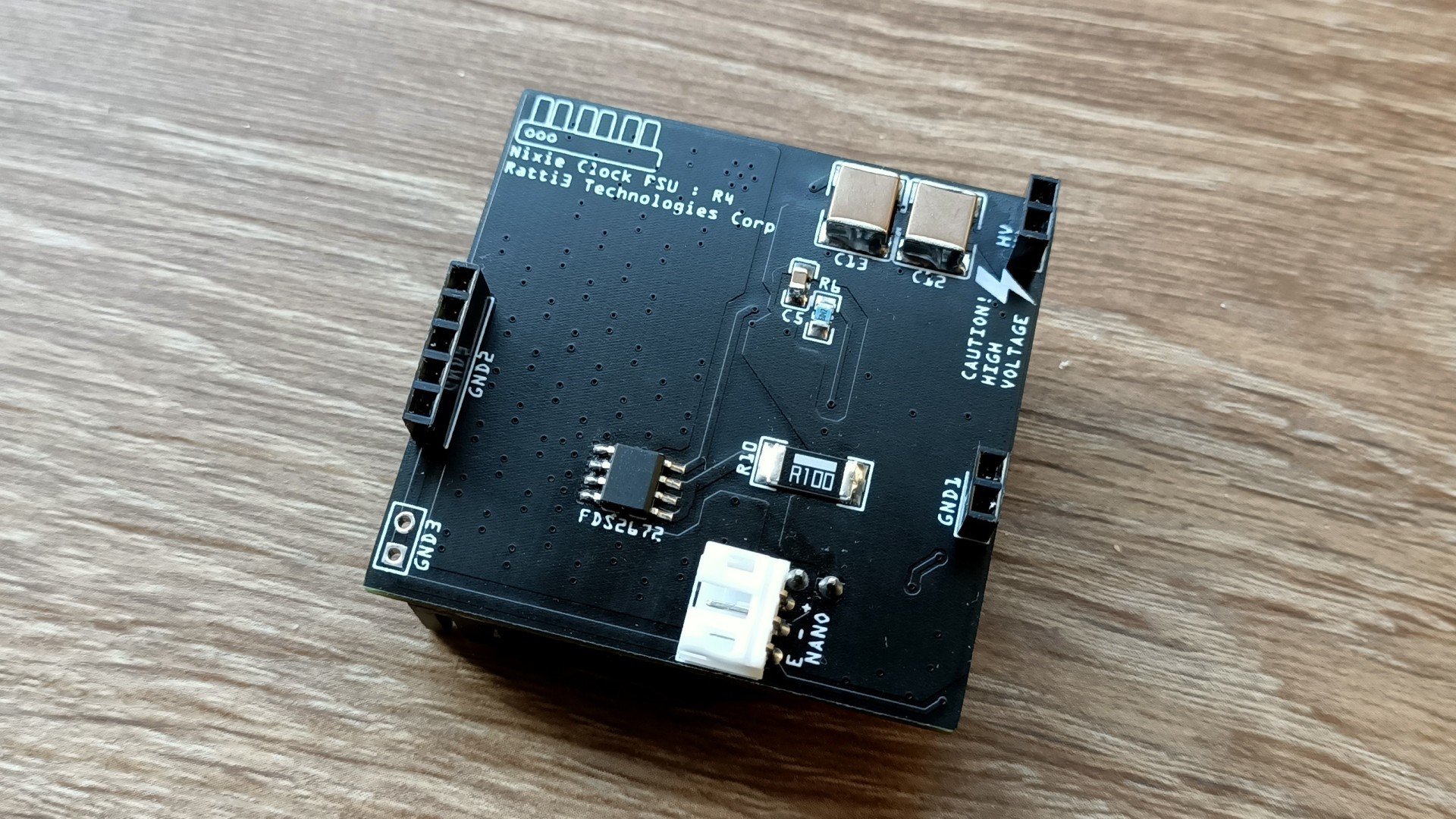
Underside of the HV adjustable PSU, JST connector for power to Arduino board ![]()
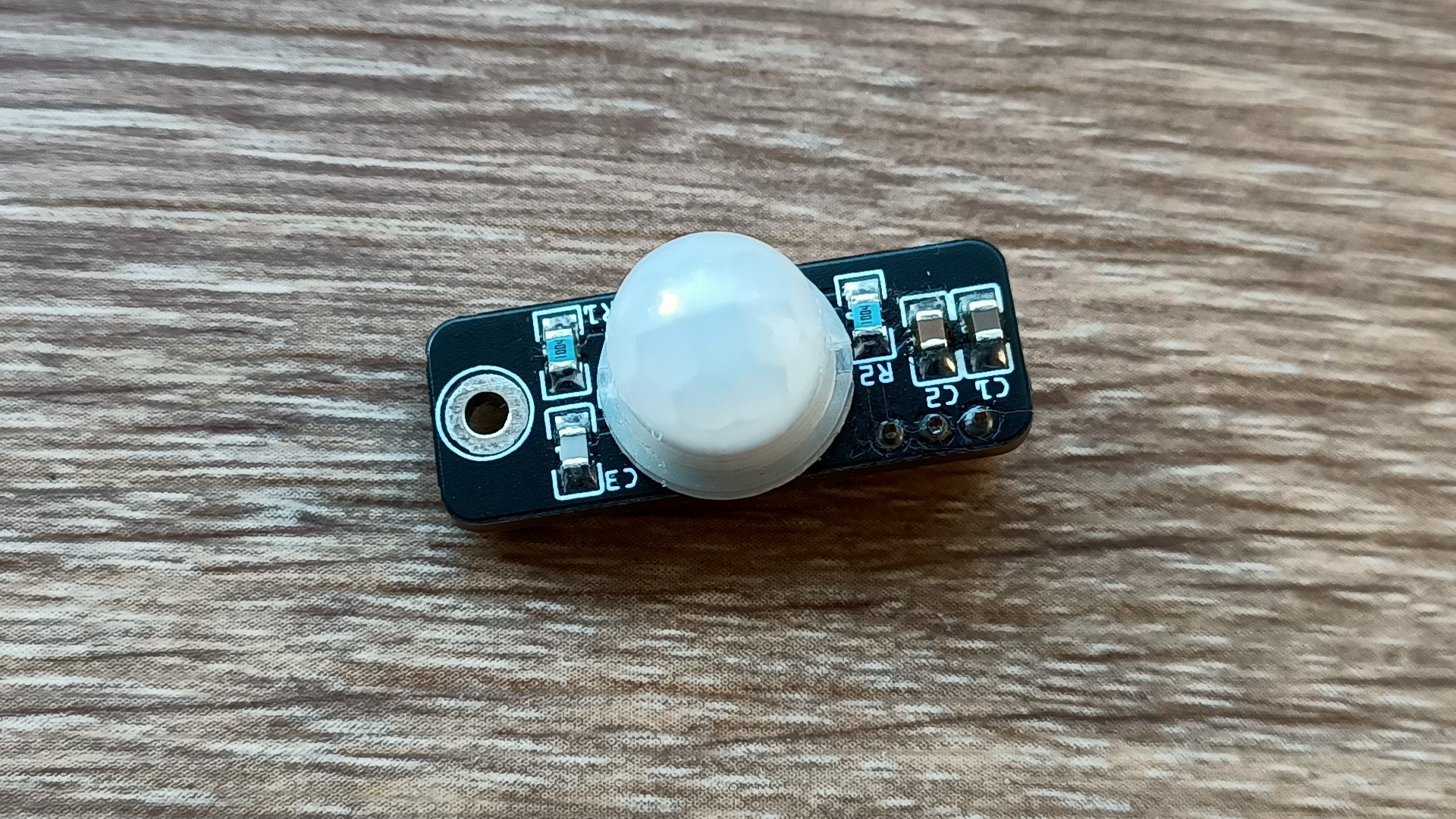
BS612 PIR Sensor with fresnel lens ![]()
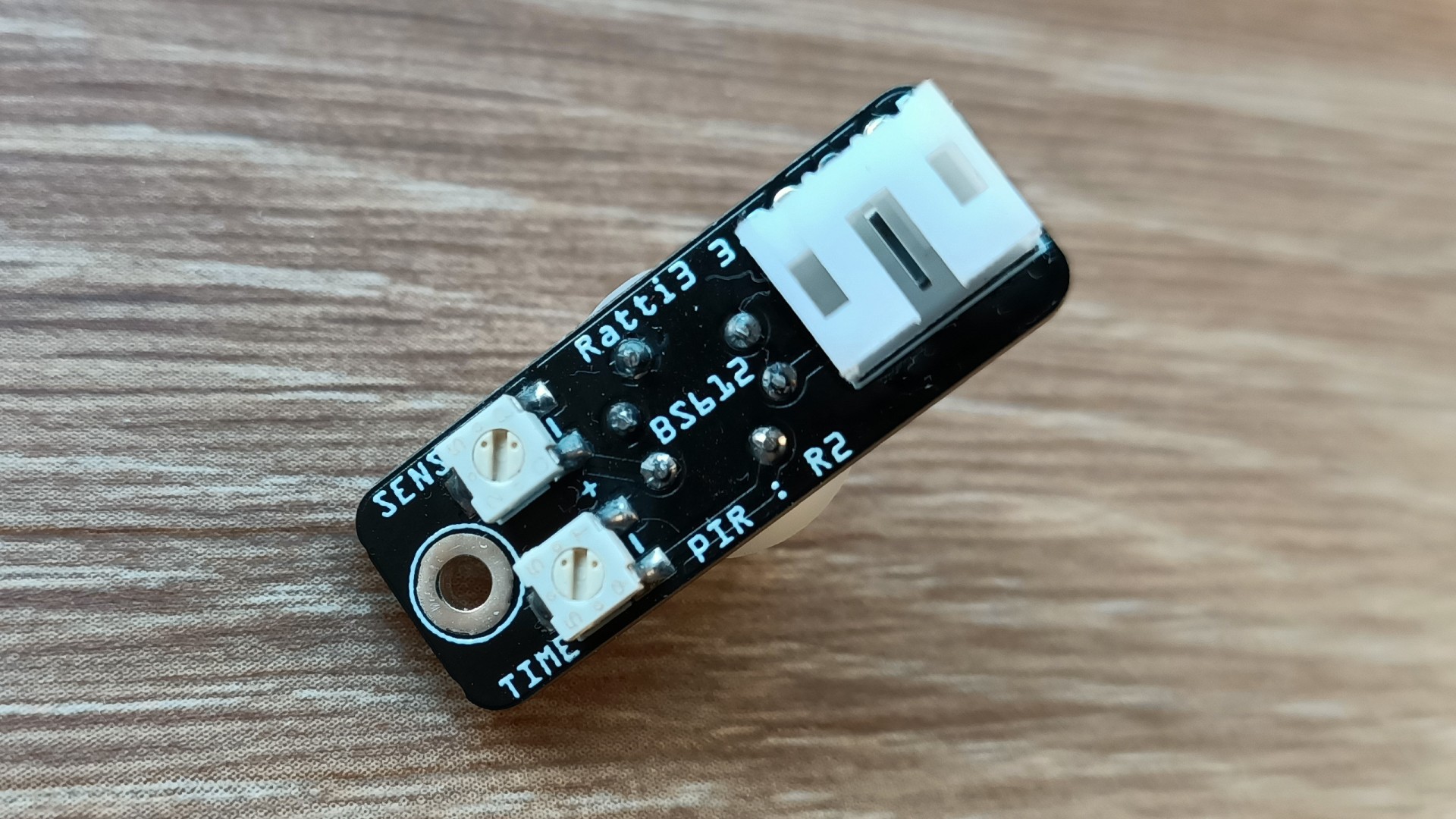
BS612 PIR Sensor with adjustable timers ![]()
BME280 environmental sensor, I will make my own version soon ![]()
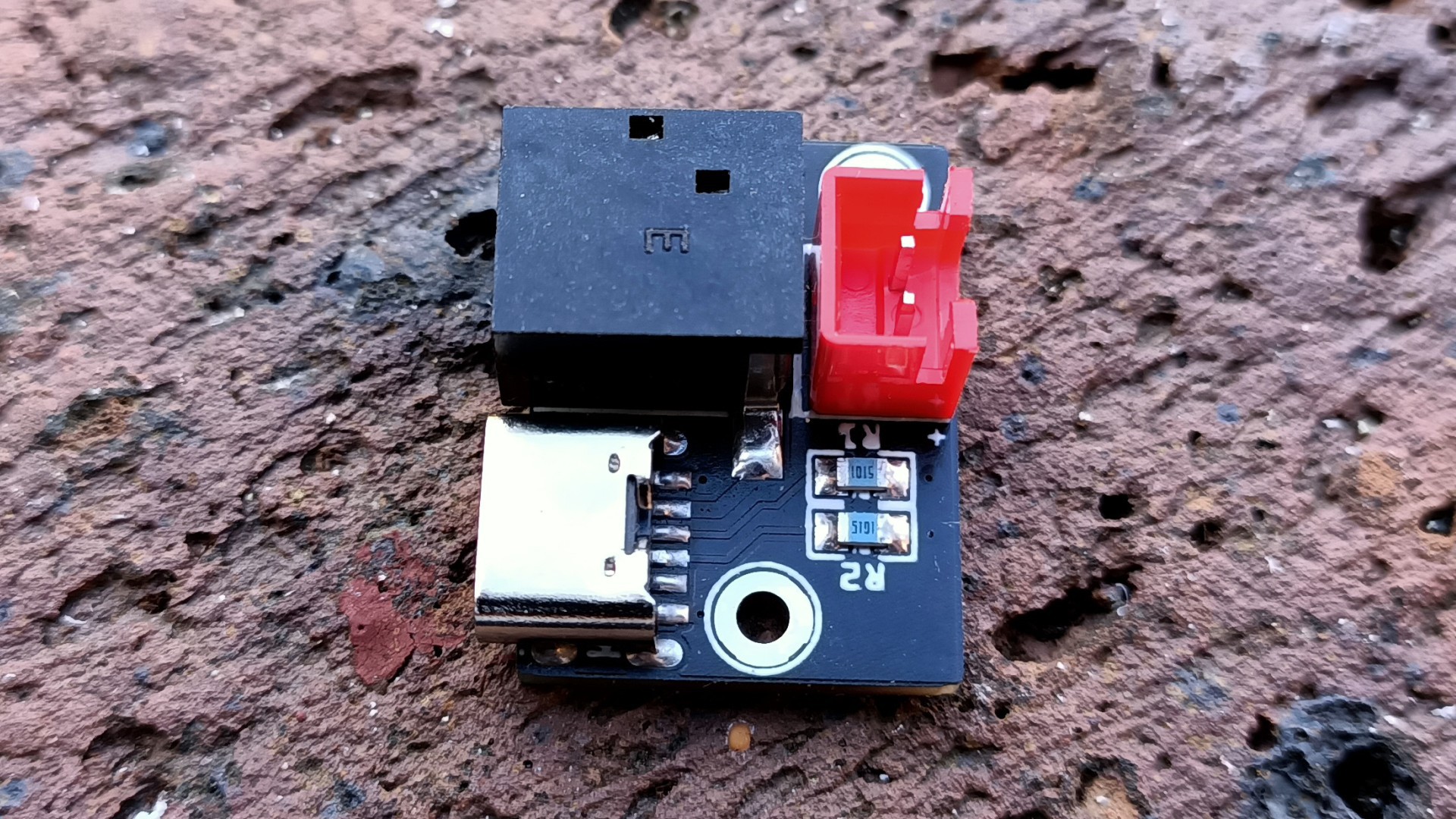
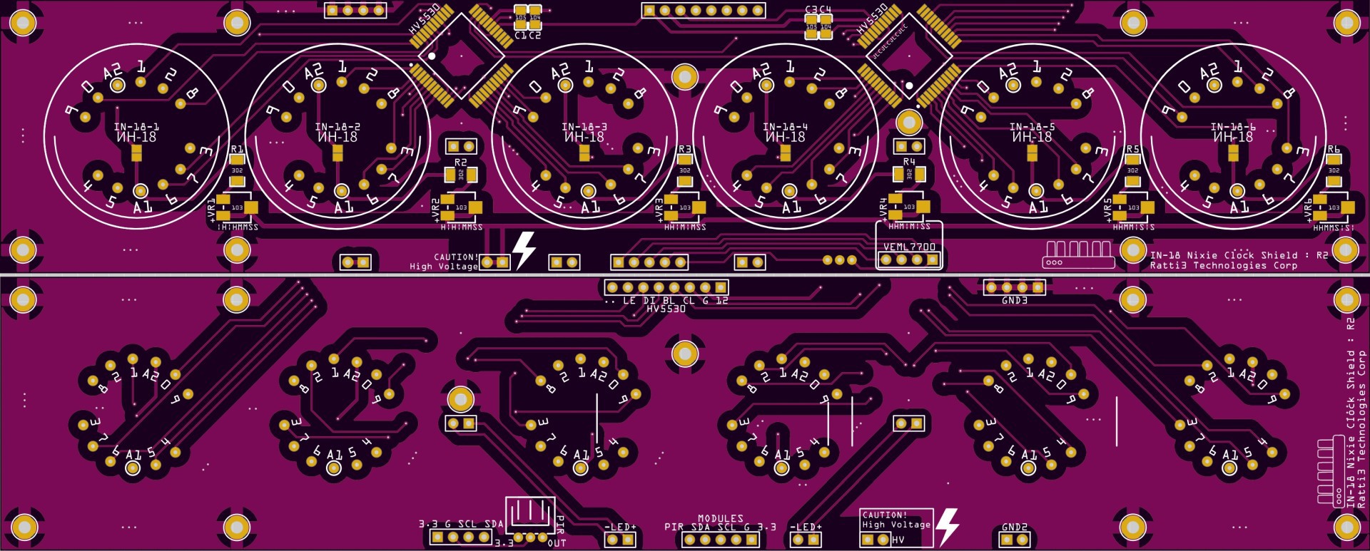
USB C and DC barrel jack power input Here are some of the PCBs viewed from EasyEDA, safety precautions have been taken in to consideration, proper seperation between the HV and the other parts of the PCB have been added. All mounting holes are connected to ground:
![]()
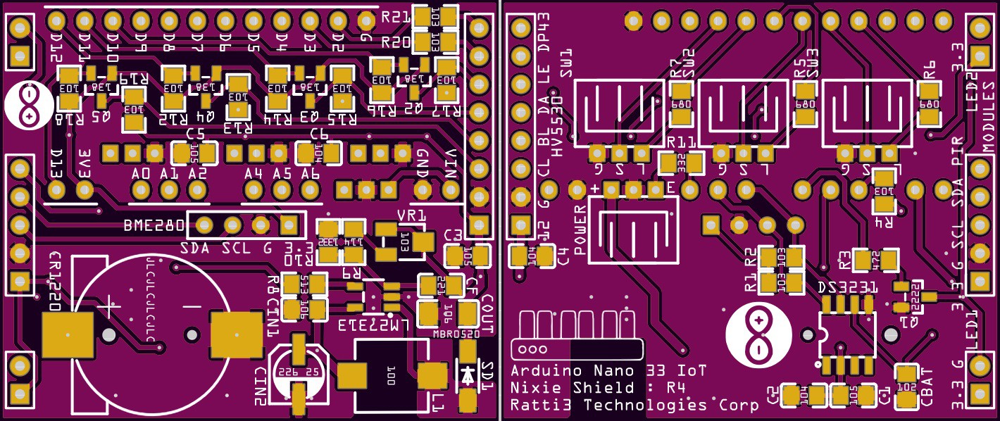
Main Nixie Board ![]()
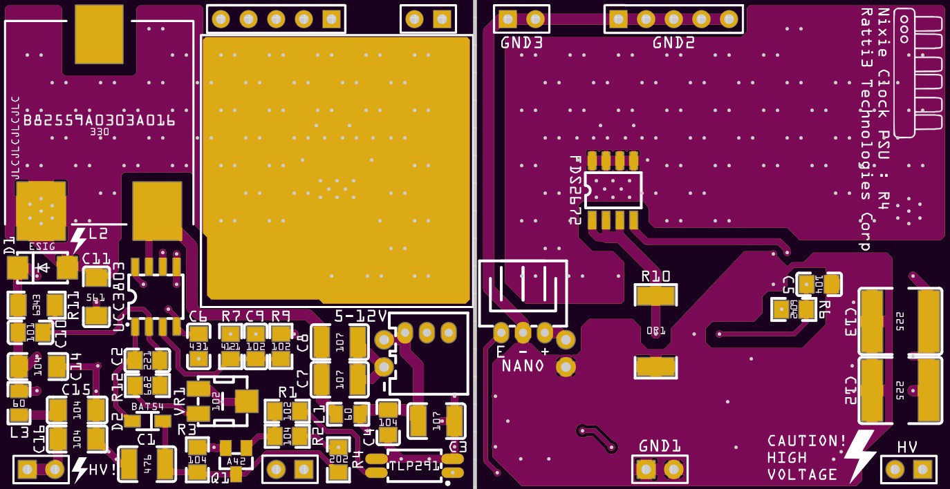
Arduino Board ![]()
PSU Board -
4Building the case
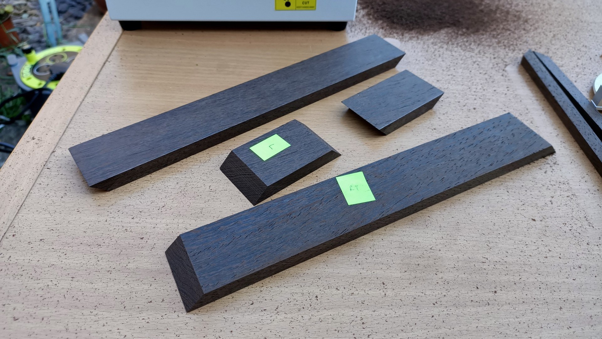
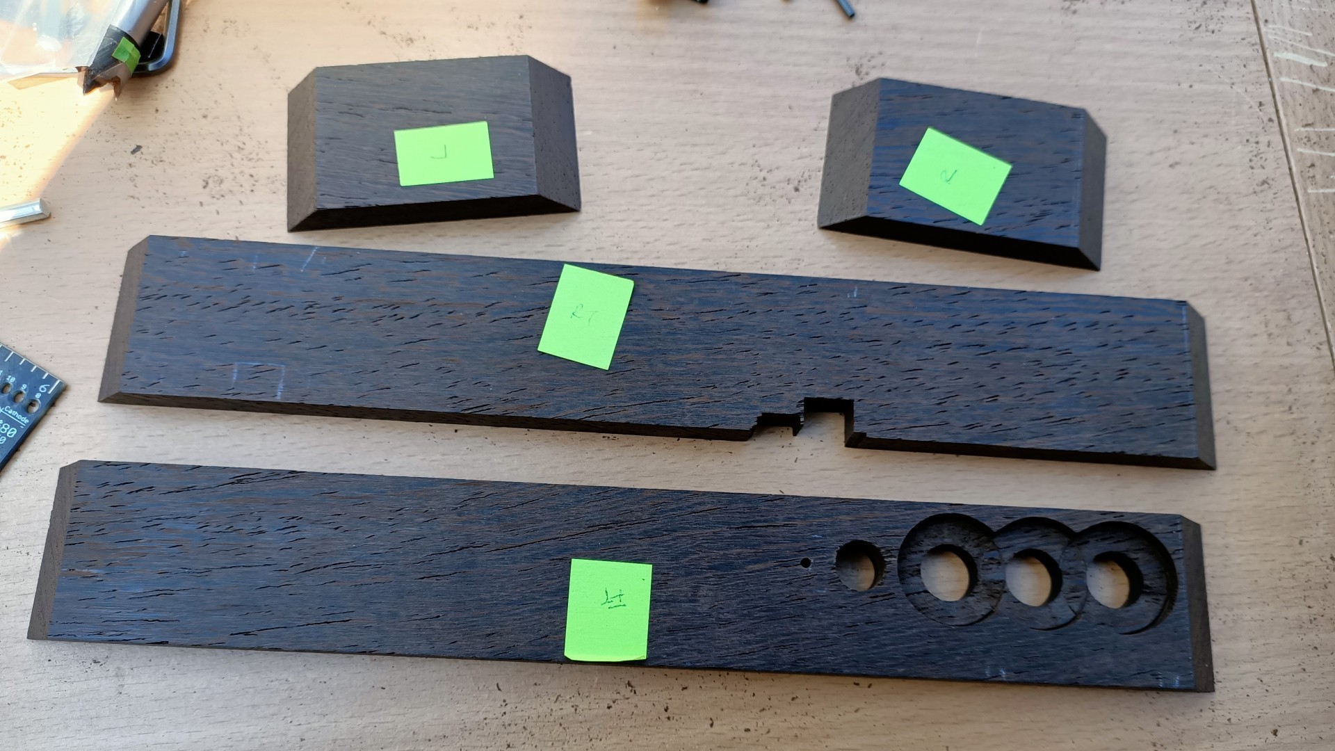
I decided to use natural wood for the case, on Ebay you can buy 9-10mm thick off cuts ranging from Wengai, Oak, Maple, Ash etc. For this clock I chose Wengai, this is an African hardwood and originates from the Congo. It's a bit brittle, but with sharp woodworking tools, it's a pleasure work with.
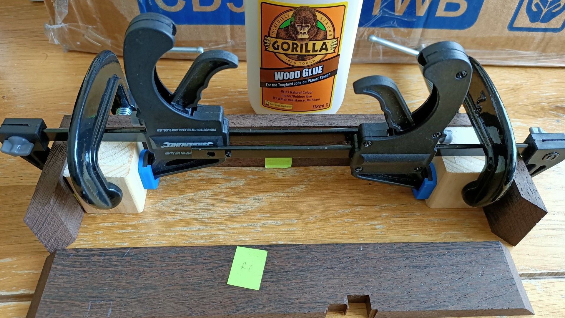
The wood panels were cut with the mini circular saw, smoothed with the belt sander and the 45° corners were done using the belt sander. I used Gorilla Wood Glue to join all the pieces together, this glue is super strong and no additional fixings are requried.
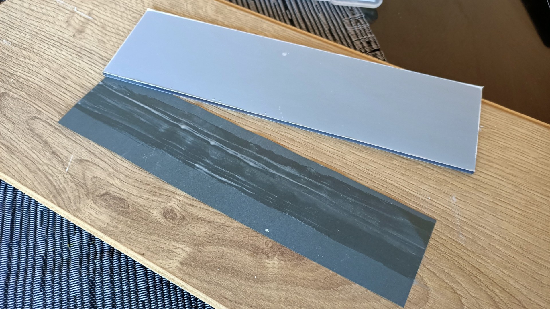
I used 3mm 9T20 Mid Transparent Grey Perspex for the top and bottom.
![]()
I used Wengai hardwood for the case, I got these 9mm thick planks from Ebay ![]()
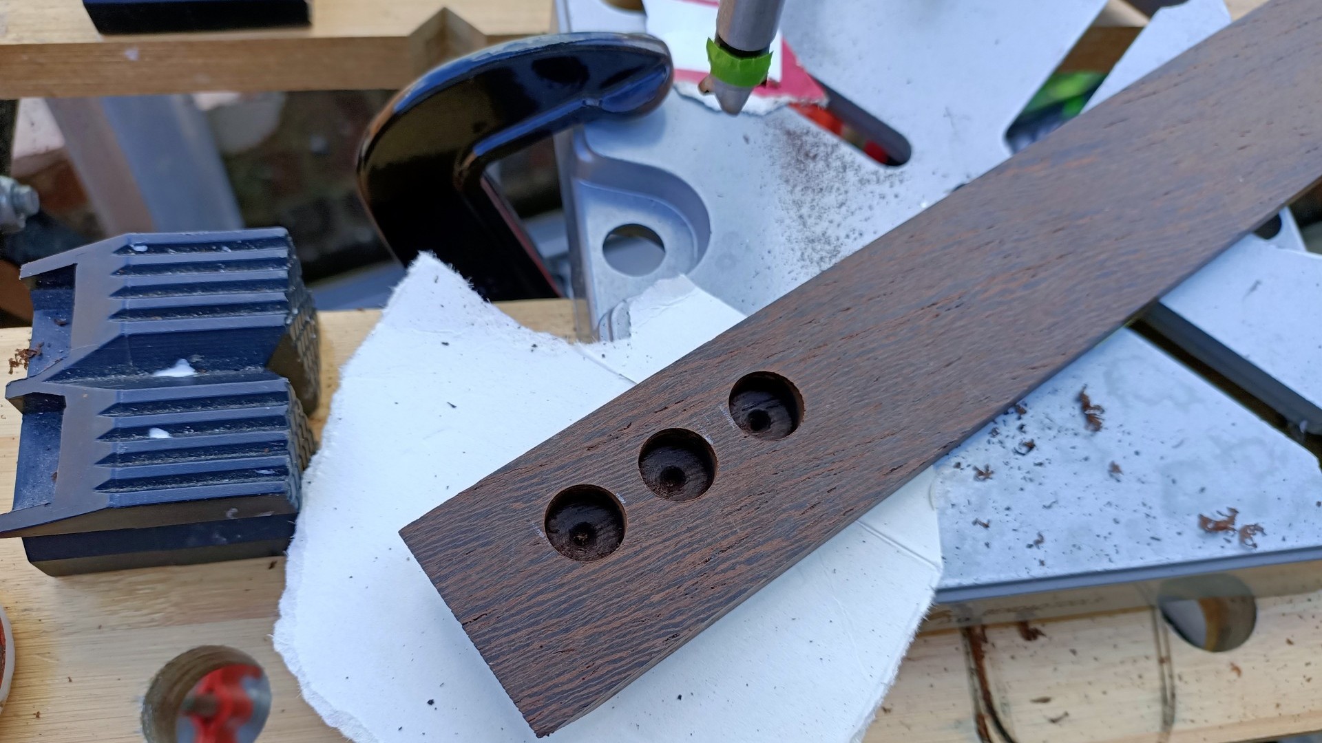
Using Forstner Drill Bits for making holes for the switches. Using a drill press helps in getting precise results ![]()
The other side requires a larger Forstner bit to make a recessed hole ![]()
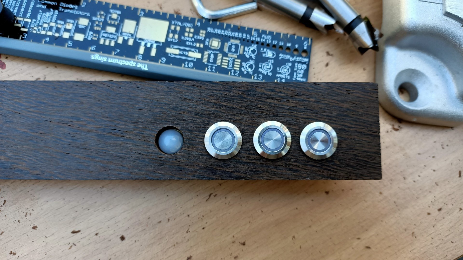
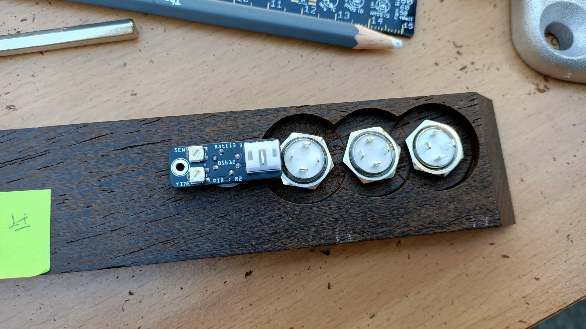
Switches and PIR sensor fit perfectly ![]()
Using Forstner Drill Bits for making holes for the switches. Using a drill press helps in getting precise results ![]()
Using Forstner Drill Bits for making holes for the switches. Using a drill press helps in getting precise results ![]()
All four pieces ready for glueing together ![]()
I used Gorilla Wood Glue and clamps to hold it together, screws not needed ![]()
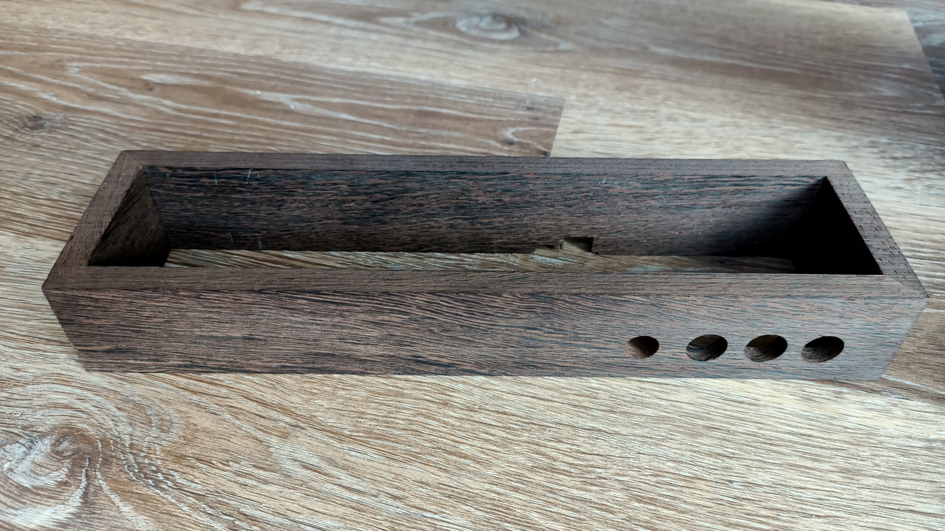
The Wengai case assembled using just glue ![]()
I used 9T20 Gloss Mid Transparent Grey Perspex for the top and bottom, 1200 grit sandpaper for a smooth edge ![]()
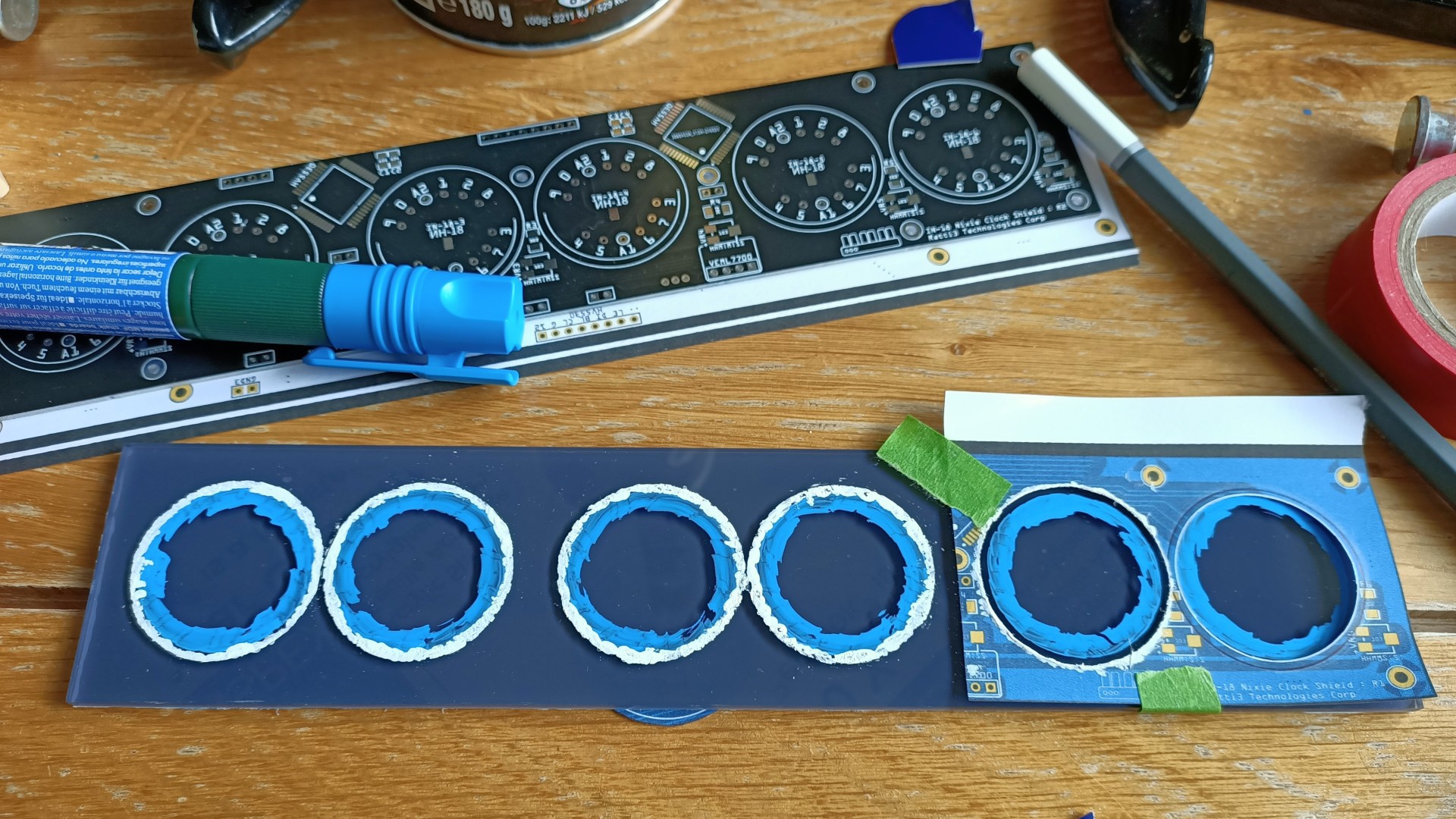
I used a paper template (from EasyEDA PCB export) to mark cutout holes ![]()
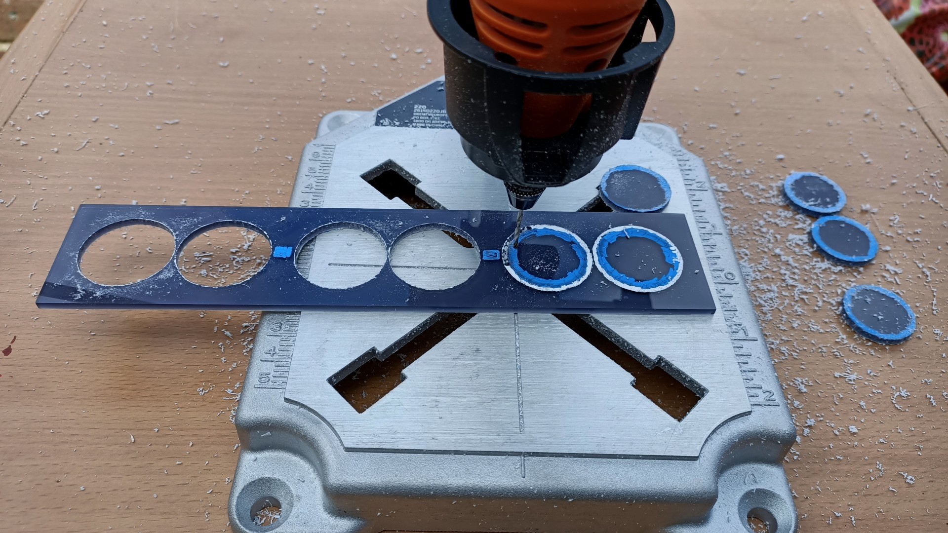
Using the rotary mini tool to cut ou holes using a 2.7mm HSS drill bit ![]()
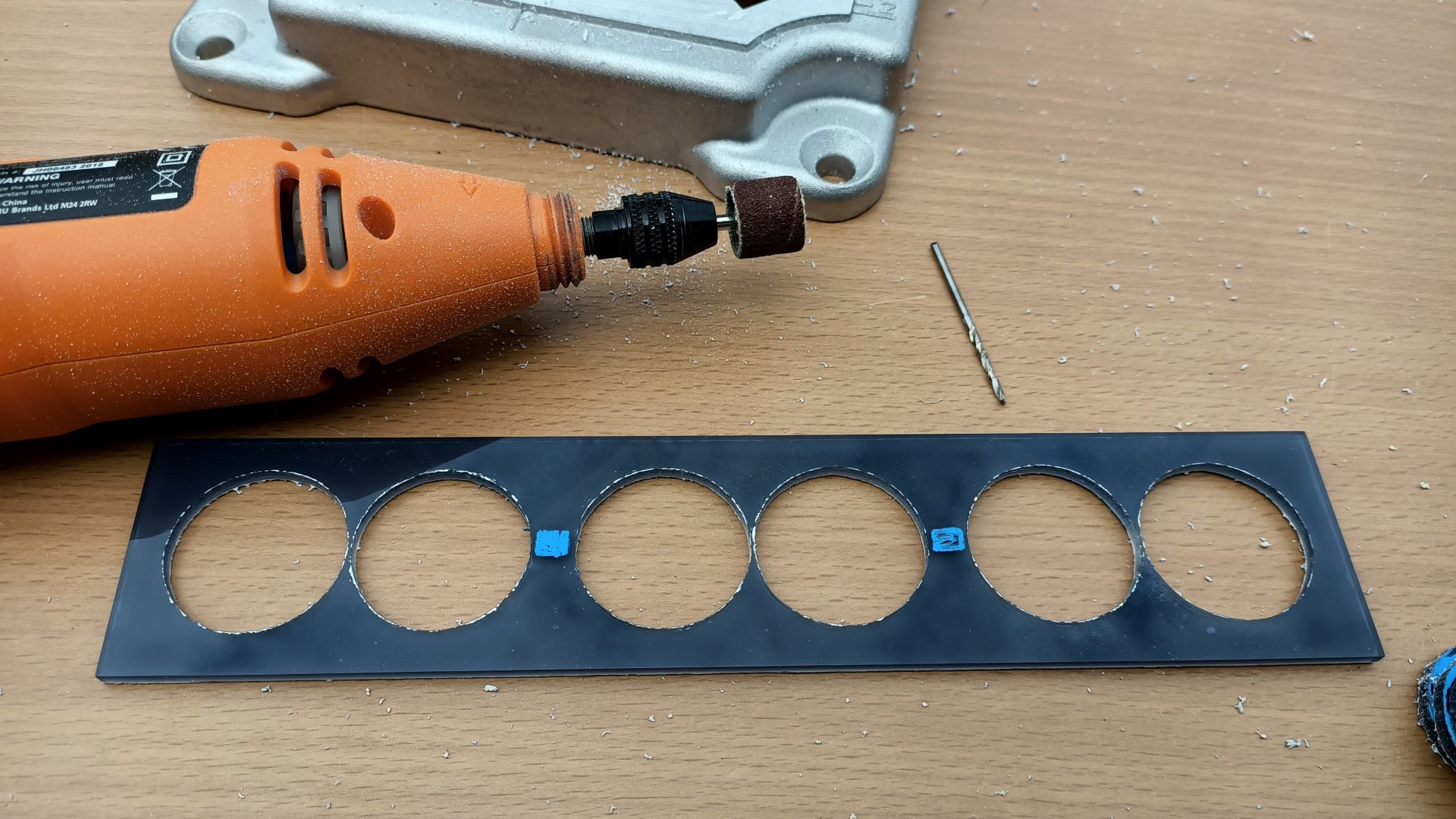
Holes cut out, a sanding attachment was used to smooth the edges ![]()
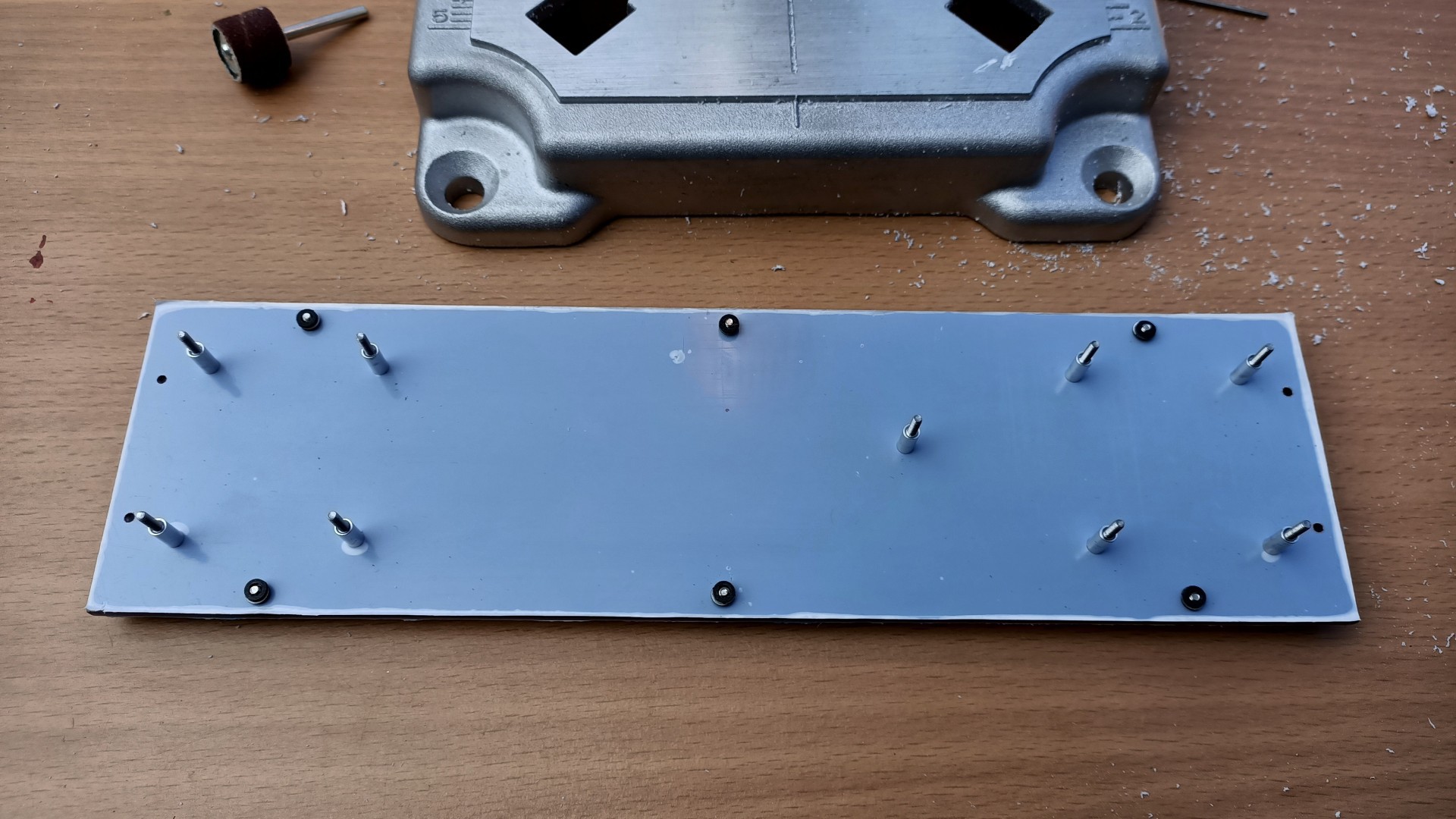
Using a paper template (from EasyEDA PCB export), 2mm mounting holes were made ![]()
Making sure it all fits ![]()
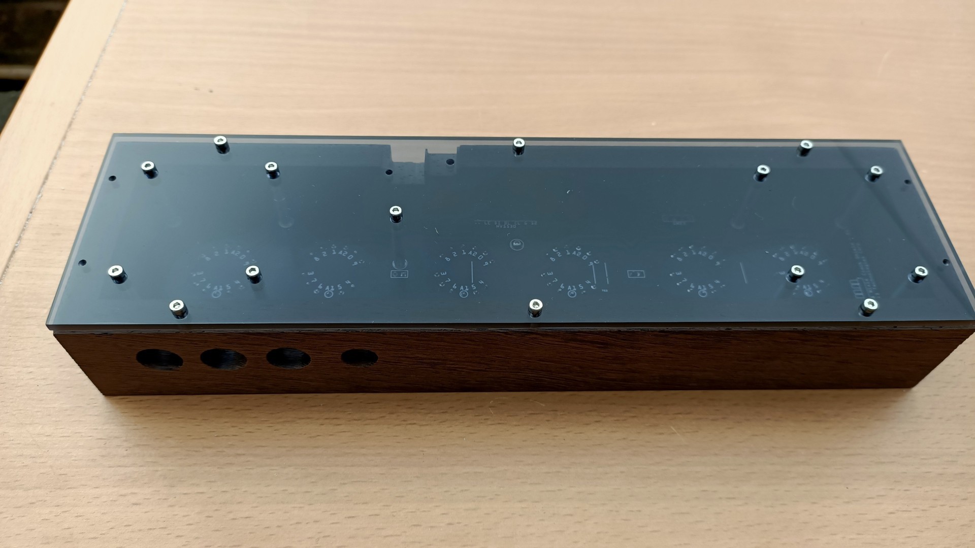
The power socket fits perfectly in the case cutout ![]()
The bottom perspex of the case with all the mounting holes with M2 machine screws -
5Assembly information
It it a good idea to use twised wires for the I2C devices, if you are running them to a different location inside the clock, this will preven the Arduino from crashing. I2C can be flaky.
The main PCB is mounted using M2 aluminium standoffs, these are available on Ebay and AliExpress in various colours and finish.
![]()
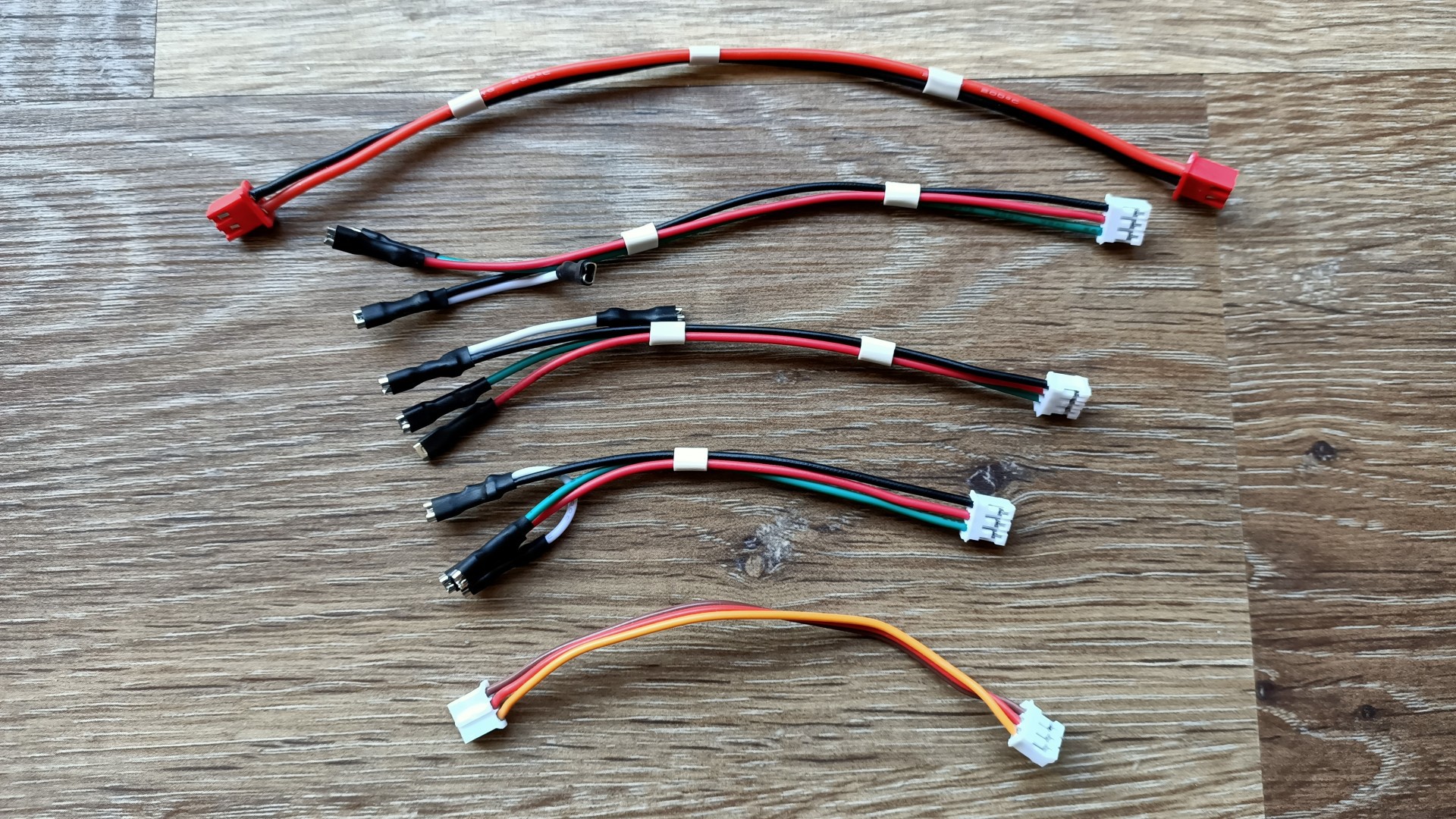
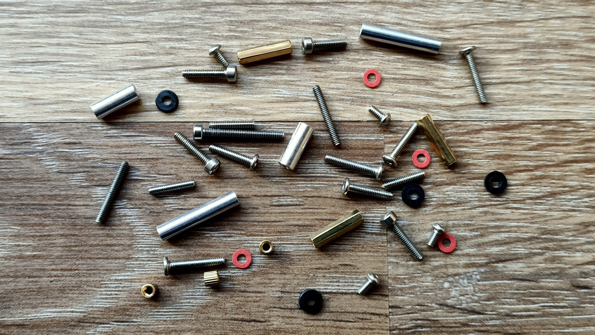
The various custom made JST cables needed ![]()
Various fastenings are required, mostly M2 sizes screws and standoffs ![]()
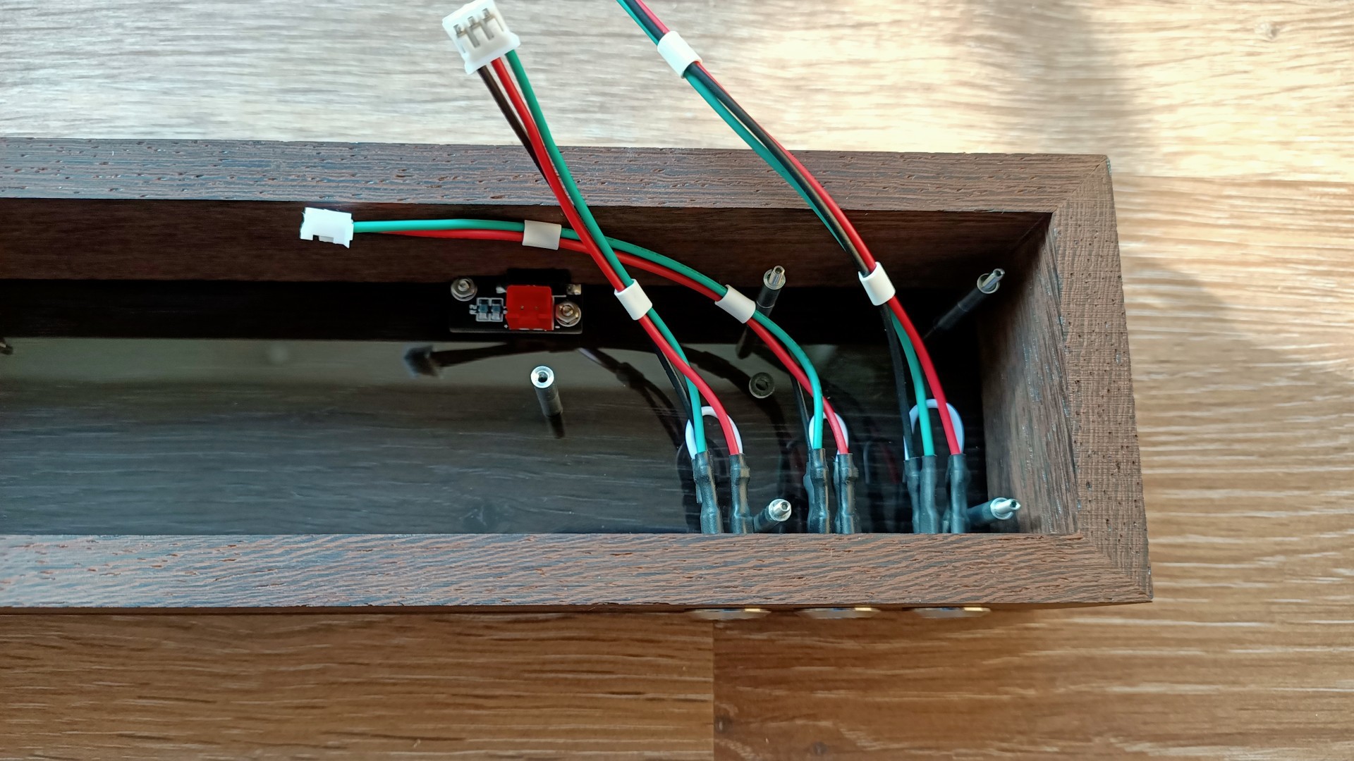
Power interconnect and switch wires connected ![]()
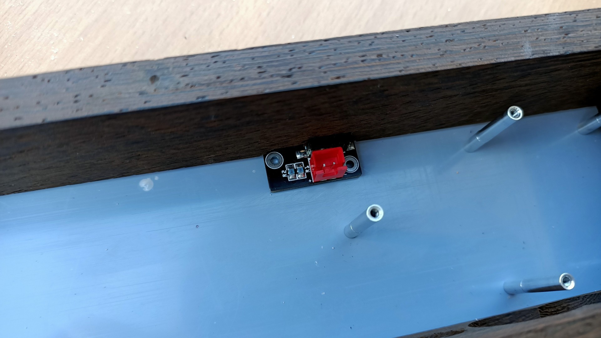
Main power input connected on bottom right ![]()
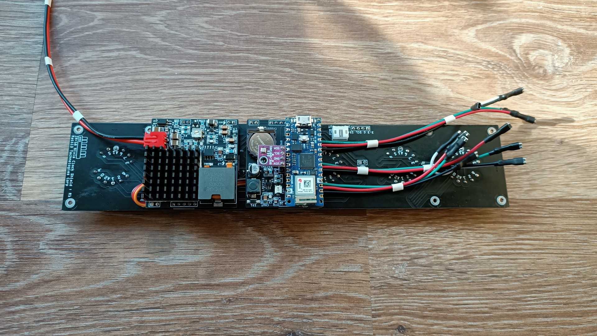
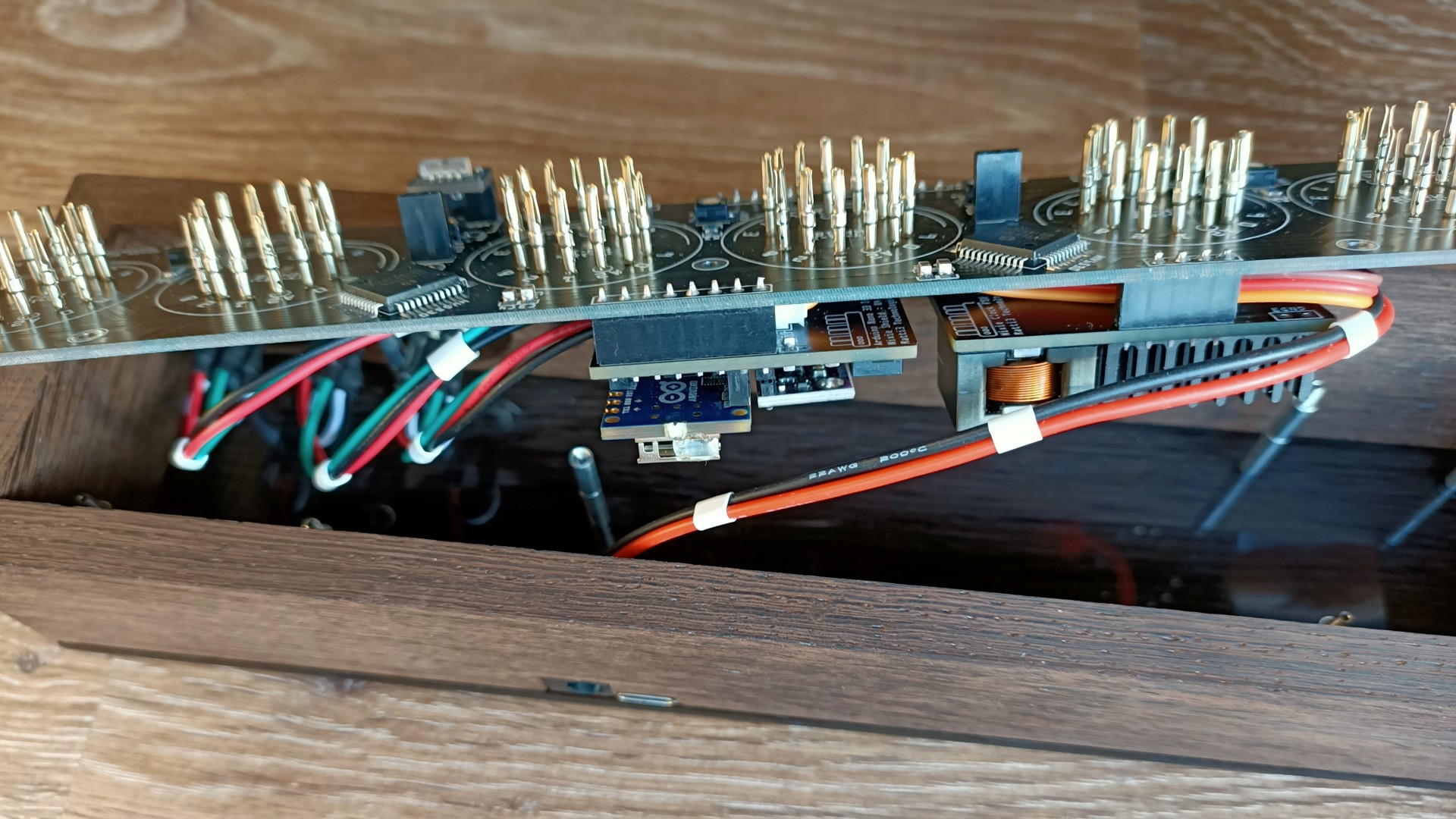
Arduino and PSU board mounted to main Nixie board ![]()
It's easier to connect the swithc side cables first before connecting to the Arduino, these are spade connectors ![]()
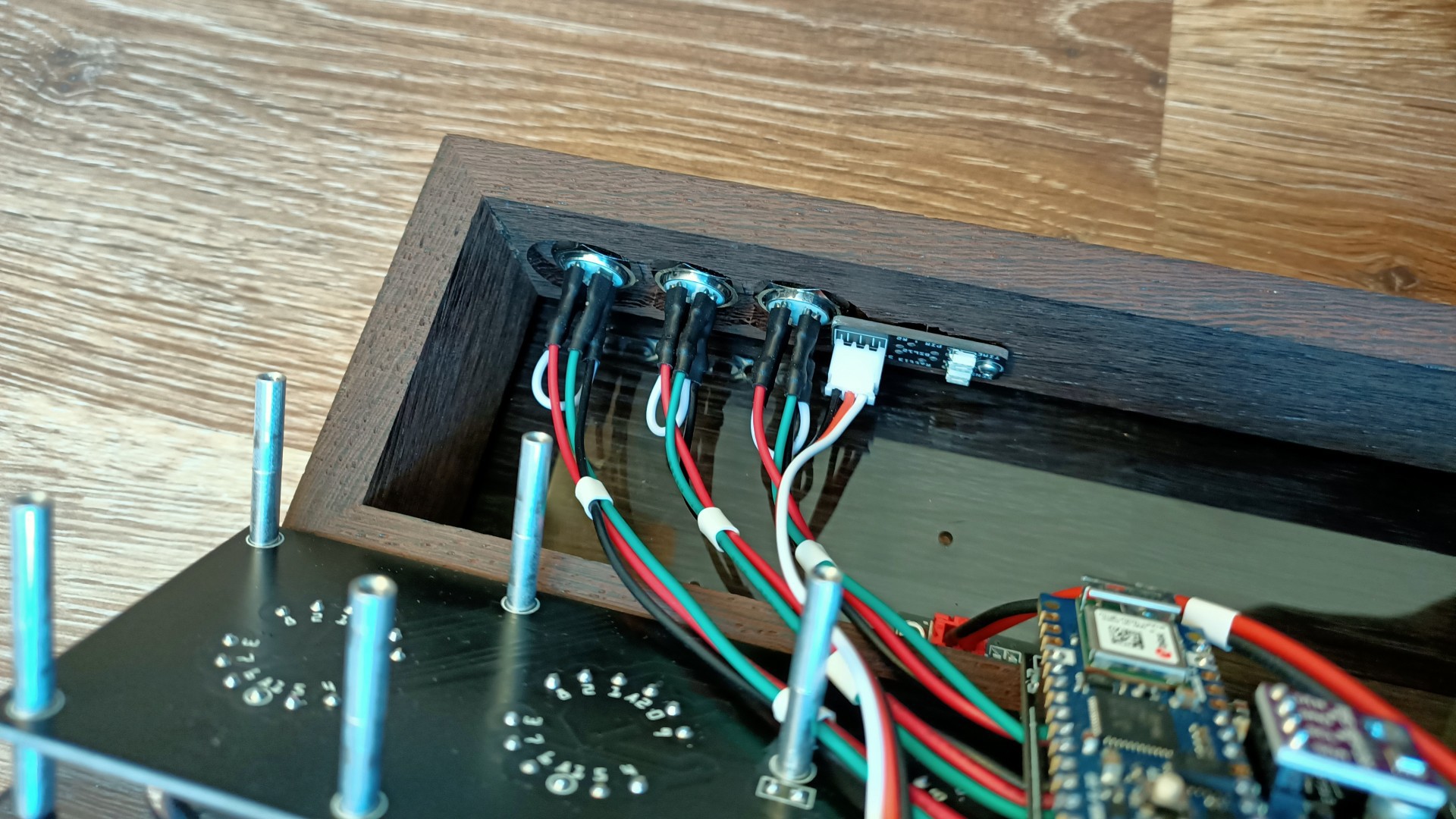
Cables attached, checking length to make sure there is no excess, long cables can cause the Arduino to crash ![]()
Connecting up the PIR sensor, this connects to the main board ![]()
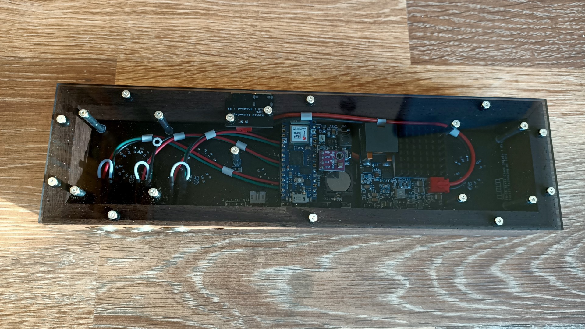
Looks nice and tidy from the bottom, the BME280 is not connected here, I recommend using twisted cables for this ![]()
The LED colon boards mounted -
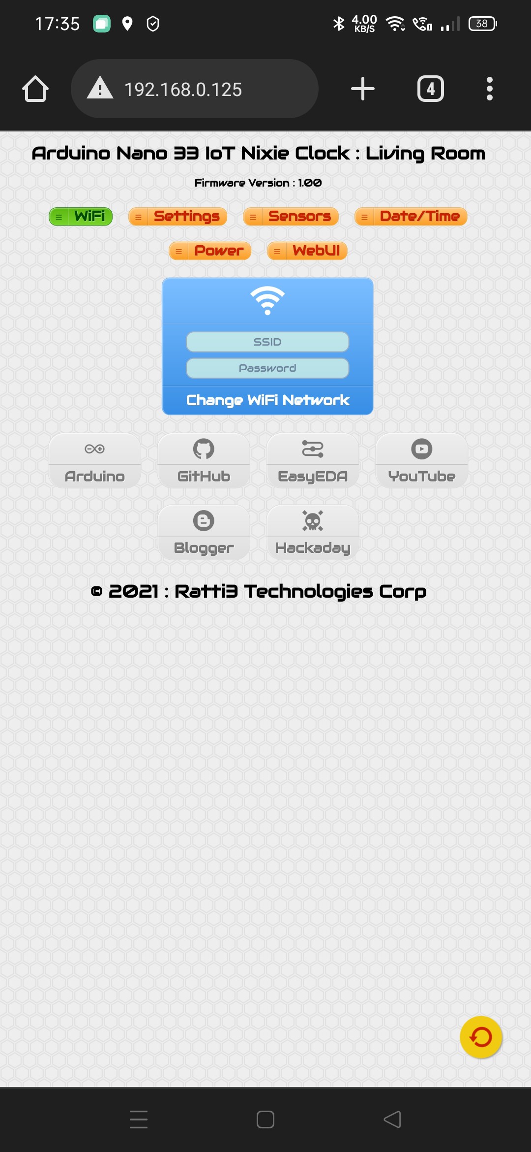
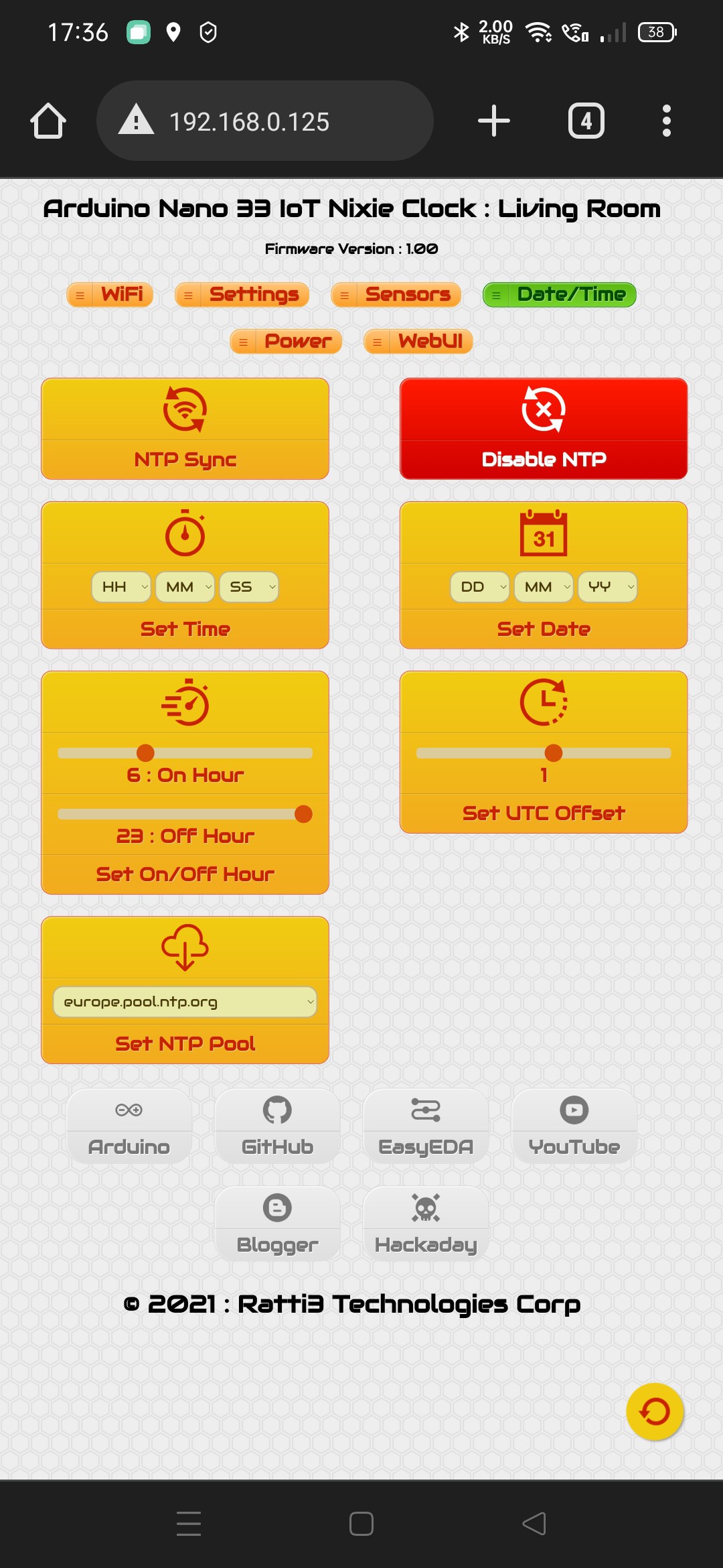
6Web UI interface
The Web UI can be used to change WiFi, date/time, NTP, sensor and power settings. All changed made are saved to the Arduino flash.
![]()
The WiFi config page ![]()
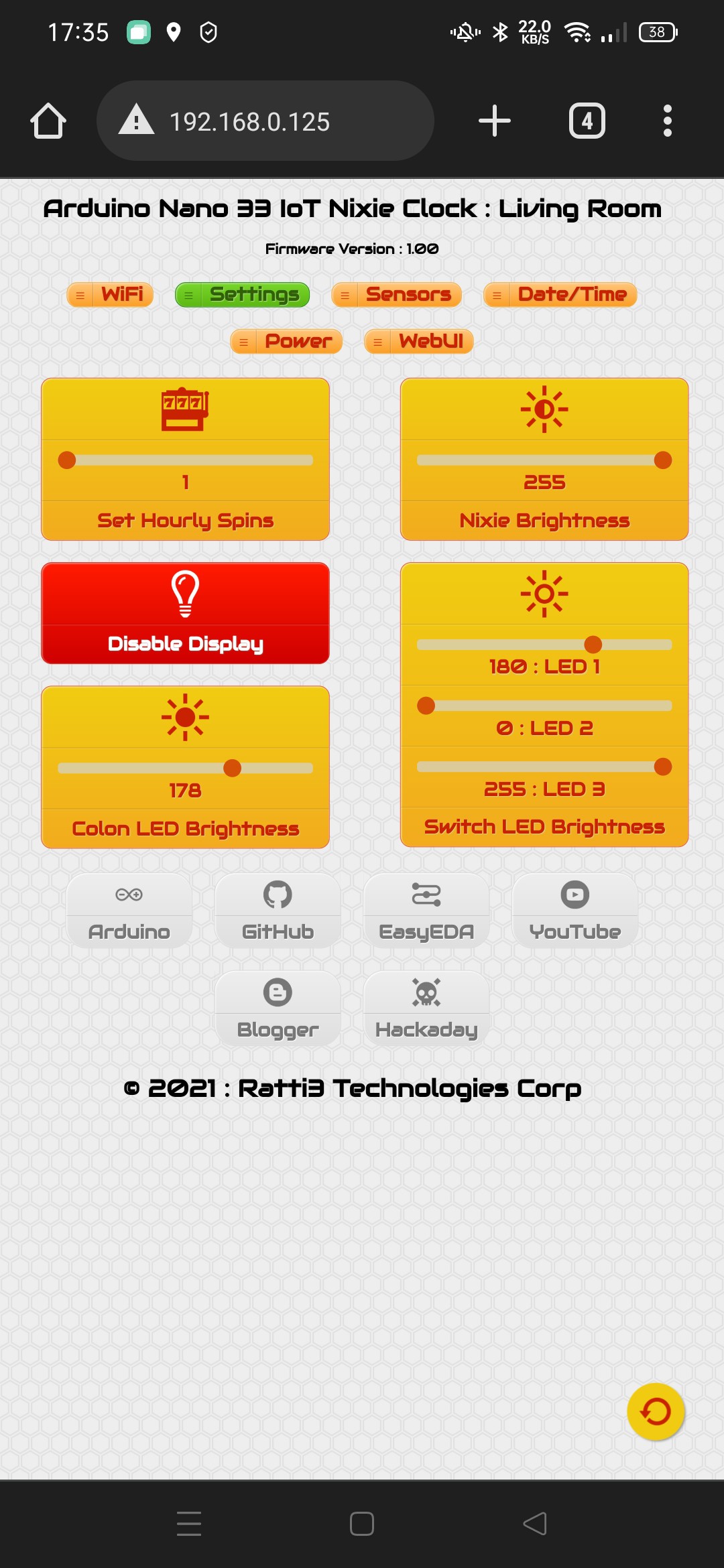
Display and brightness settings ![]()
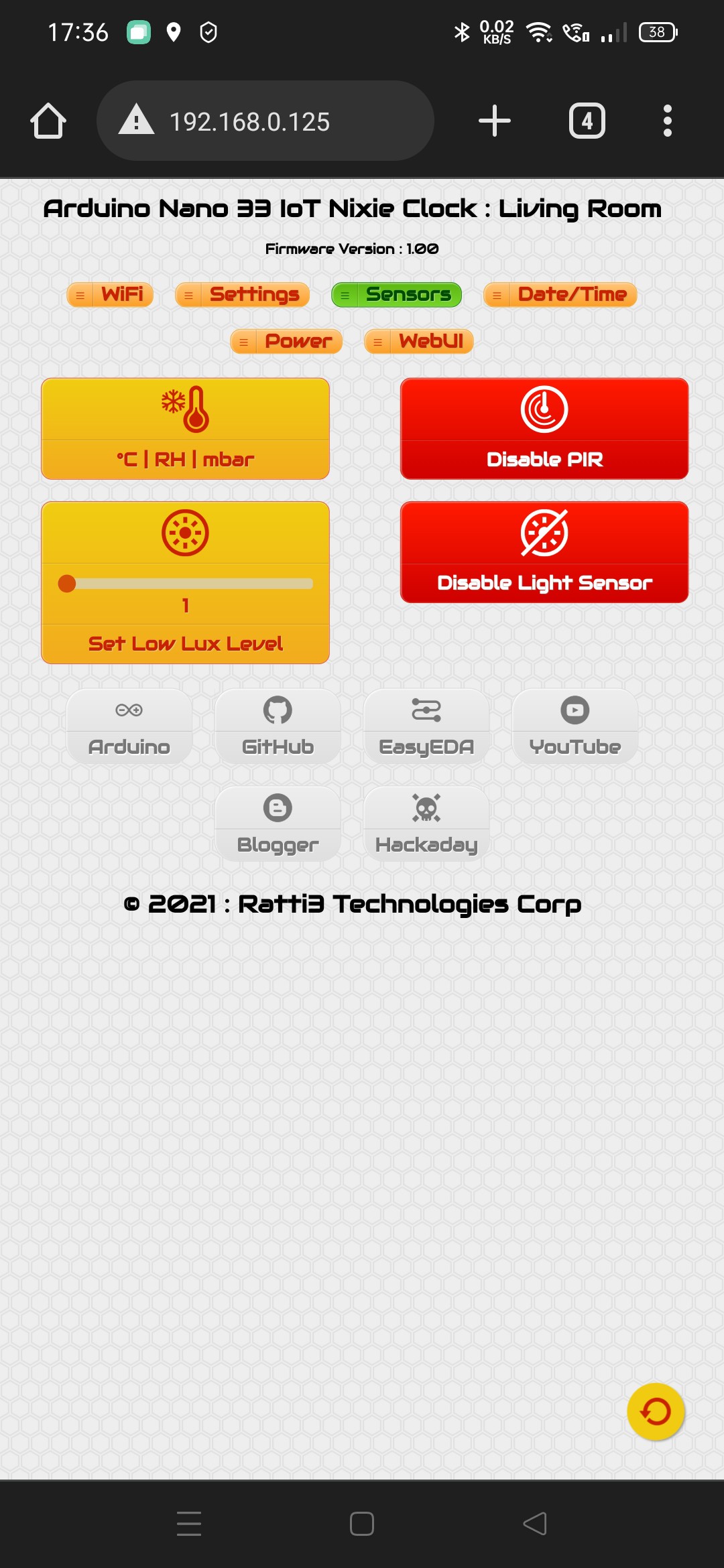
Sensor related settings ![]()
Manual date/time adjust and NTP settings ![]()
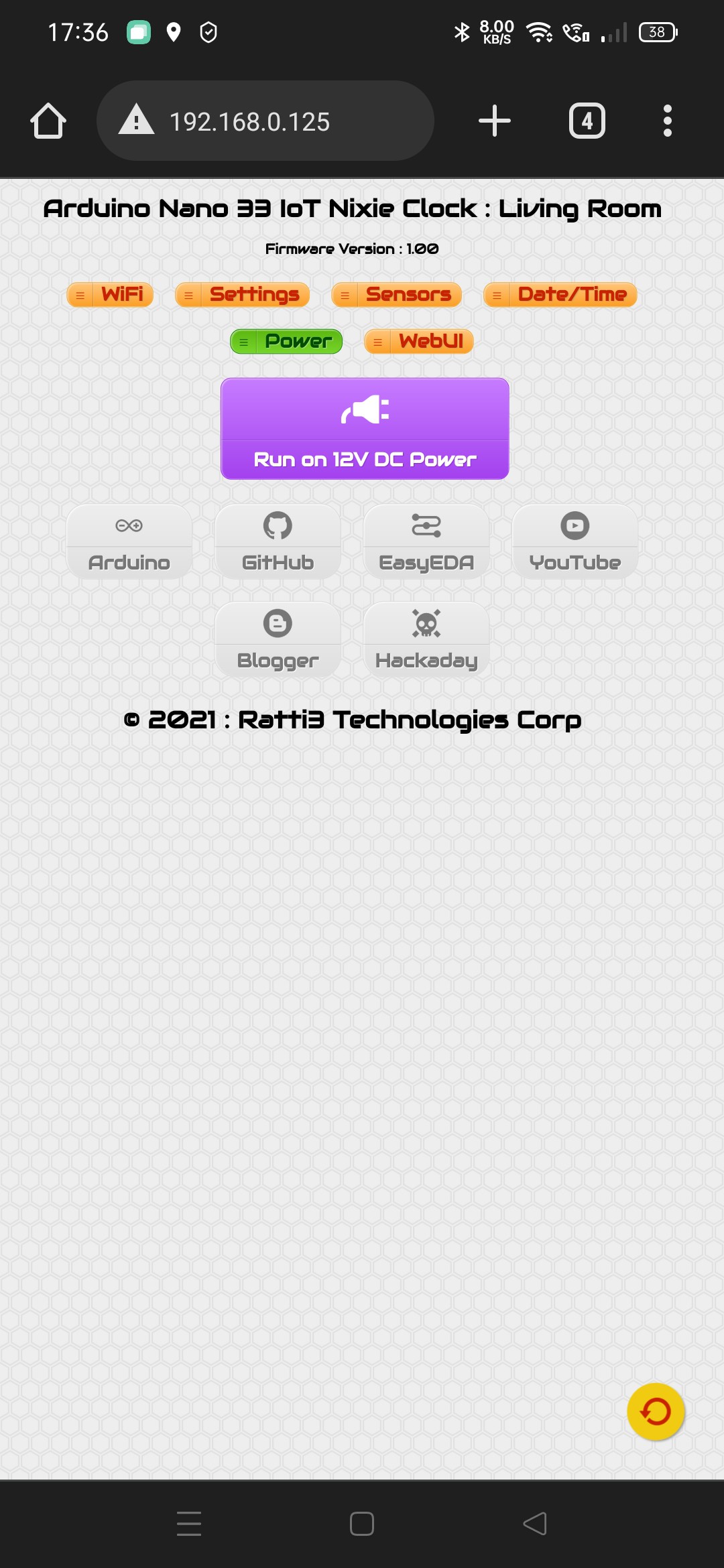
Switch between 12V and 5V power supply, not setting this will not damage anything ![]()
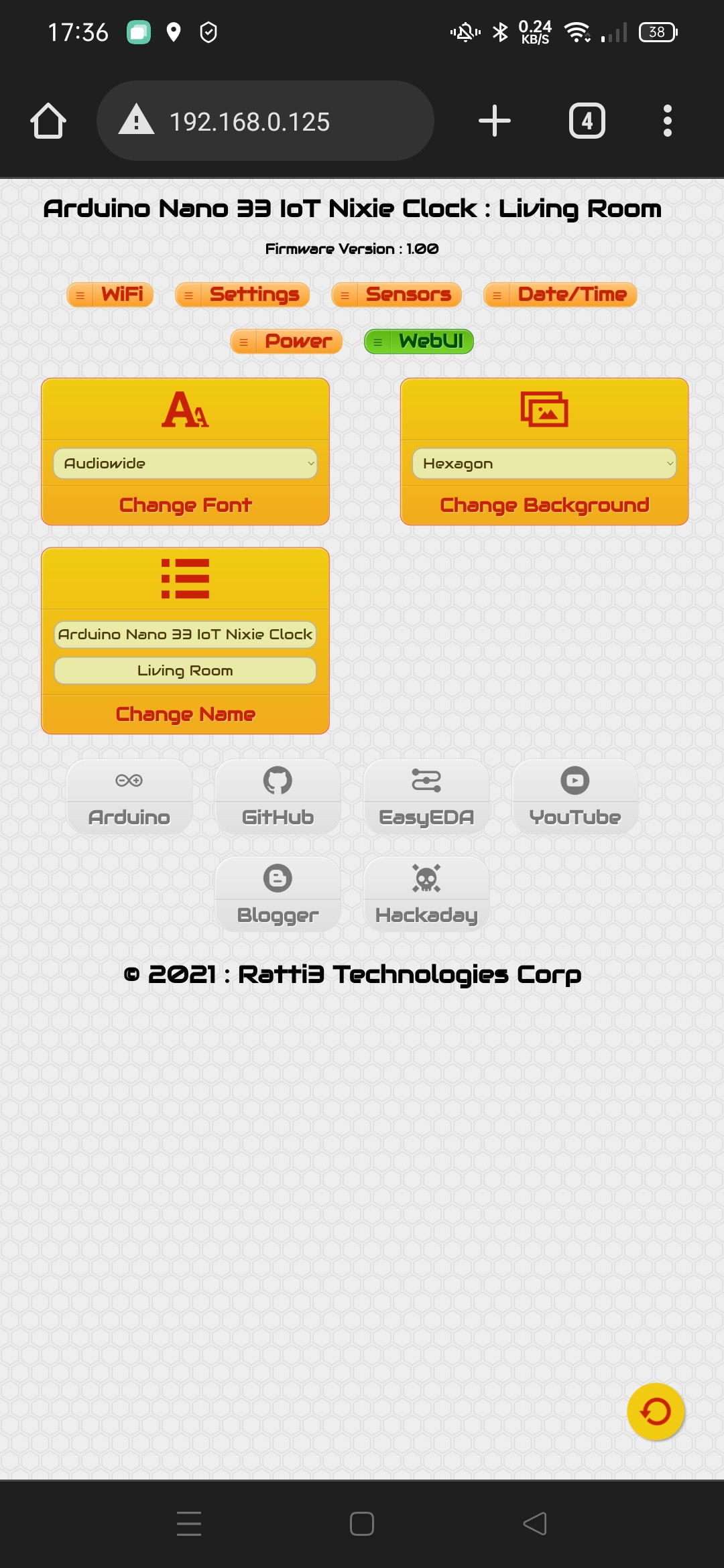
Settings for changing the WebUI appearance and you can give the clock a name -
7The code
The code was written using the Arduino IDE, due to the amount of code, I've used seperate .CPP and .H files.
The following libraries are required, everytime a library is updated and I'm updating the code, I test the latest version and mention it in the code. Currently the following libraries are required:
// v1.8.13 WiFi - https://github.com/arduino-libraries/WiFiNINA
#include <WiFiNINA.h>
// v1.8.13 WiFi UDP - https://github.com/arduino-libraries/WiFiNINA
#include <WiFiUdp.h>
// v3.2.1  NTP Client - https://github.com/arduino-libraries/NTPClient
#include <NTPClient.h>
// v1.0.0  Use Flash as EEPROM - https://github.com/cmaglie/FlashStorage
#include <FlashStorage.h>
// v2.0.3  DS3231 RTC - https://github.com/adafruit/RTClib
#include <RTClib.h>
// v1.1.5  Required by BME280 - https://github.com/adafruit/Adafruit_Sensor
#include <Adafruit_Sensor.h>
// v2.2.2  BME280 Environmental Sensor - https://github.com/adafruit/Adafruit_BME280_Library
#include <Adafruit_BME280.h>
// v2.1.1  VEML7700 Light Sensor - https://github.com/adafruit/Adafruit_VEML7700
#include <Adafruit_VEML7700.h>
// v1.9.2  Button - https://github.com/bxparks/AceButton
#include <AceButton.h>
The default AP password is located in the Secrets.h file:
#define WIFI_AP_SSID "NixieClock"
#define WIFI_AP_PASS "nixieclock"
Settings.h has some default values that are overwritten when using the Web UI, these can be changed if required:
// Store PWM HV5530 brightness level 1 - 255 (Note: 0 would turn off the Nixies but leave the HV on)
byte flashBrightness = 255;
// Store Enable/Disable NTP boolean
bool flashNTP = 1;
// Store NTP pool address (1 = africa, 2 = asia, 3 = europe, 4 = north america, 5 = oceania, 6 = south america)
byte flashNTPPool = 3;
// Store display On Hour
byte flashOnHour = 6;
// Store display Off hour
byte flashOffHour = 23;
// Store Enable/Disable PIR
bool flashPIR = 1;
// Store Enable/Disable Light Sensor
bool flashLight = 1;
// Set power supply mode, setting to 1 enables the 5v to 12v booster for the HV5530
bool flashUSB = 1;
// The WebUI font
byte flashFont = 1;
// The WebUI background
byte flashBackground = 4;
// UTC offset in hours
byte flashUTCOffset = 0;
// Colon LED Brightness via PWM
byte flashColon = 15;
// Switch 1-3 LED Brightness via PWM (note these values can be the same if the correct resistors are used for the LEDs)
byte flashLED1 = 180;
byte flashLED2 = 30;
byte flashLED3 = 170;
// Nixie Spin Cycles per minute
byte flashSpin = 1;
// Low Lux Level Threshold
byte flashLux = 1;
// Stores the NTP pool to query, changed via flashNTPPool
const char* ntpServerName = "europe.pool.ntp.org";
All the HTML for the Web UI is located in WiFiTask.cpp, there are no links to external images, all icons are done via SVG XML.
-
8Parts not in the EasyEDA BOM
I should mention anything that is not part of the schematic won't be in the EasyEDA BOM. Here is a list of additional parts and components, I'll just mention the sites they can be found:
- 10mm LED low profile mometary push button switch [AliExpress/Ebay]
- Pre terminated wires with spade connectors for use with the 10mm switches, usually sold with the switches [AliExpress/Ebay]
- Wengai African Hardwood 9-10mm thick [Ebay]
- 3mm 9T20 Transparent Mid Grey Perspex [Ebay]
- Fresnel Lens [LCSC]
- Low profile female and male headers. Check EasyEDA schematic notes for part number
- JST plugs [LCSC]
- Nixie socket pins [AliExpress/Ebay]
- Nixie tubes [Ebay]
- Gorilla wood glue [Ebay]
- M2 Hex socket screws, washers, standoffs and nuts [AliExpress/Ebay]
- Silicon DC wires 22-26 AWG [Ebay]
- CR1220 lithium coin cell [Ebay]
- 25x25x10mm heatsink [AliExpress/Ebay]
- Thermal glue for heatsink [Amazon/Ebay]
- BME280 or BMP280 sensor (code adjustment may be required) [AliExpress/Ebay]
- 400, 600 and 1200 grit wet sandpaper [Local Hardware Store]
Arduino Nano 33 IoT Modular Nixie Clock with WebUI
USB 5V or 12V, Motion, Light, Temperature, Humidity & Pressure Sensors. NTP Sync, Web Interface for changing settings/time & wifi.


Discussions
Become a Hackaday.io Member
Create an account to leave a comment. Already have an account? Log In.